Search
The Renewable Energy site for Do-It-Yourselfers
Final Flow Rate
Calibration
Flow Rate Measurement
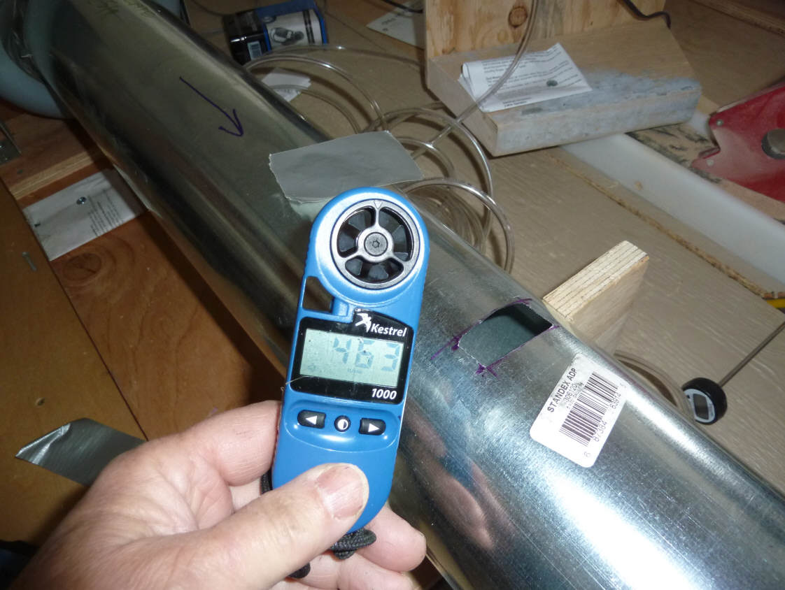
For most of the testing, I use a
Kestrel wind meter (see below) to set up the flow rates. Both the
reference collector and the collector being tested have an opening near the end
of the outlet duct cut to fit the kestrel meter -- I just insert the Kestrel
into the opening until the turbine is in the center of the duct, then, using the
hold function to retain the reading, pull the Kestrel out and read it. I
normally use an average of three readings, but the readings are pretty
consistent.
Since the the reference collector and
the collector being tested have identical ducting and fan arrangements, when the
Kestrel reads the same for both, the flow rates should be very close.
Flow rate = (Duct Area)*(Kestrel
Velocity) * (Correction factor)
Where Correction Factor corrects
for velocity profiles etc (see below)
For example, if a flow velocity
of 690 fpm is read, and the 5 inch duct has an area of 0.136 ft^2, then the
flow is:
Flow rate = (0.136 ft^2)*(690
ft/min) *(0.82) = 76.9 cfm
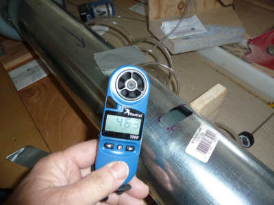
Kestrel wind meter |

Kestrel being used to read the 5 inch exit duct flow velocity. |
Correction Factor
The Kestrel wind meter is subject to
some errors having to do with the velocity profile across the width of the duct,
and with the Kestrel blocking a bit of the flow path just by being there.
I also think that the lower density of the air both to our high altitude (5000
ft) and the higher temperature of the air may effect the Kestrel readings in
that its readings are based on how fast the little turbine rotates, which in
turn depends on the air forces on the turbine blades which depend (at least to
some degree) on the air density.
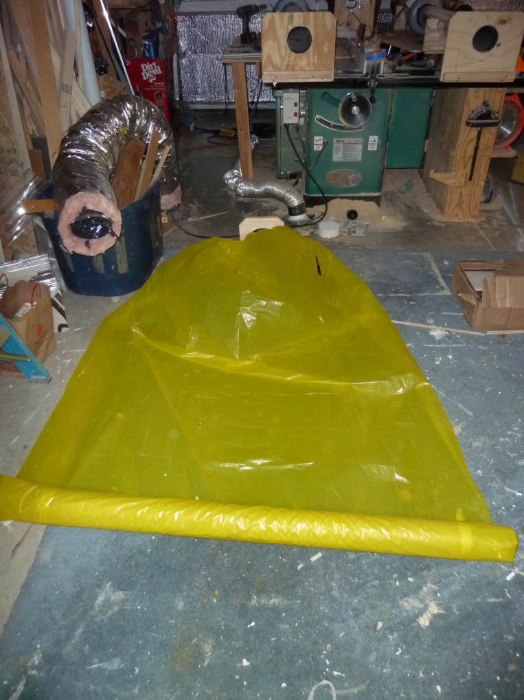
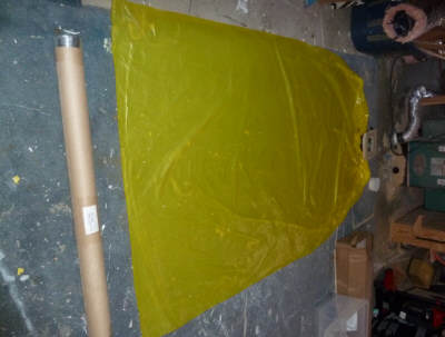
So, to calibrate the Kestrel velocity
readings, I use the fill time time for a larger (54 cf) poly bag. I
believe that the fill time for the bag gives accurate flow rates, and I use
these flow rates calculated from bag fill times to derive a correction factor
for the Kestrel readings.
I've worked on the bag system to try
to make it as precise as possible:
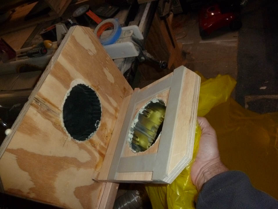
- A flat plate on the end of the
exit duct allows the bag to be quickly and precisely coupled to the fitting
on the bag. This allows for good timing of the start of the fill
process, and for low flow resistance as the bag fills.

This fixture allows a quick and accurate coupling of
the end of the outlet duct to the bag, and
a good seal of the bag to the duct end.
Note the weather stripping and the clamp ridge
at the bottom of the duct end plate. |
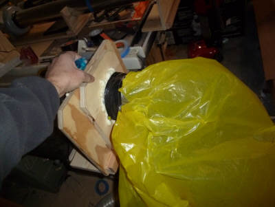
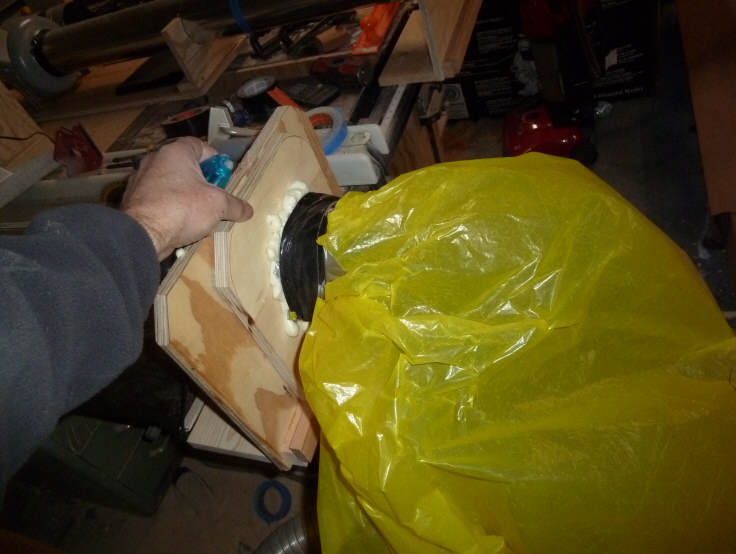
Just holding the bag fitting to the duct end plate
allows a good, leak free and low resistance
coupling of the bag to the duct end. |
- The bag is carefully rolled
flat before each inflation to get all the air out of it.
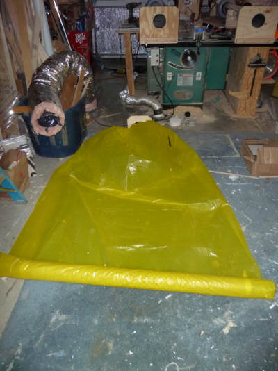
Rolling the bag flat before inflation. |
The bag is rolled over the cardboard tube to empty
all of the air out of it. |
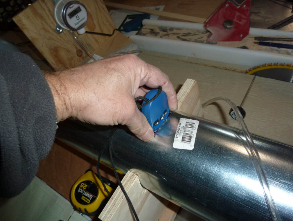
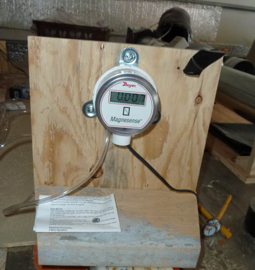
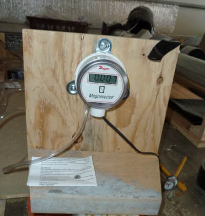
- The end point for the bag fill is determined by hooking up the
manometer to read the static pressure near the end of the exit duct.
As the bag approaches the very end of its fill, the manometer pressure rises
rapidly. I use a rise of 0.1 inches of water as the point to click the
stop watch at the end of the fill.
If you don't have a manometer, the end of the fill is pretty easy to time
without it. The bag sort of snaps into its final form, and makes the
timing of the end of fill pretty precise without the manometer.
The bag must cause some back pressure when its being filled, and this
must in turn reduce the flow rate slightly. But, the back pressure is
very low -- less than 0.01 inches of water, so I think the effect is small.
The flow rate is determined from the
bag fill time as:
Flow Rate = (Bag Volume) / (Fill
Time)
So, with a bag volume of 53.8 cf,
and a fill time of (say) 35 seconds or 0.58 minutes
Flow Rate = (53.8 ft^3) / (0.58
minute) = 92.8 cfm
The chart just below shows the
results of timing bag fills and equivalent Kestrel velocities for several
different flow rates. The Kestrel Correction Factor is determined from
these fills at different flow rates.
<chart>
Gary January 9, 2011