Search
The Renewable Energy site for Do-It-Yourselfers
Solar Pond Water
Heater -- Construction
|
The pictures below show the
construction of the solar pond water heater prototype 3.
The parts:
|
|
Pond Frame,
Insulation, and Liner
You need to have a flat place that
stays relatively dry (i.e. does not become a puddle after rains). The
ground that the pond sits on must be level. I used some washed gravel that
I had on hand to make sure the pond base drained well, but this is not necessary
-- it can go right on the lawn.
Set a patio block or footing block to
support each of the 4 corners of the pond frame. Make these as level with
each other as possible.
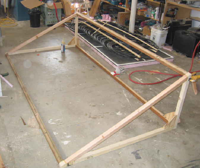
The pond frame for the prototype is 4
ft by 8 ft outside dimensions. It is constructed with 2 by lumber. I
used mitered corners, however, and butt joint would work just as well. It
would be a good idea to use treated lumber for the boards that are in contact with
the ground.

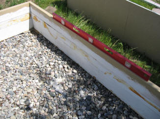
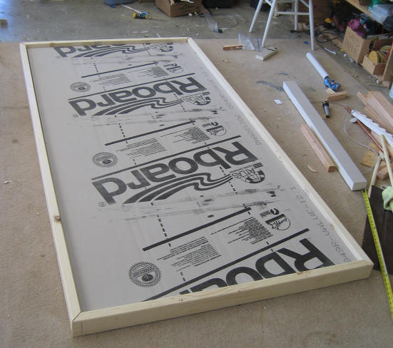
The pond frame -- 16 inches high and
4 ft by 8 ft outside dimensions.
Make sure its level and square.
Check each of the edge boards with a
level.
Check for square by measuring the
diagonals -- when they are equal, the frame is square.
Make sure the grass or gravel
underneath is flat -- the bottom insulation board sits right on the ground.
The pipes from the solar heater to
the house need to be buried and insulated to prevent freezing, and to avoid high
heat loss.
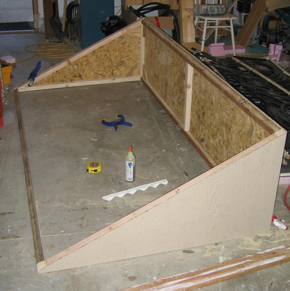
Insulation Board:
The edge frame and the bottom are
lined with 2 inch polyisocyanurate (Atlas R-Board in this case). These
panels can be easily cut to size with a long blade razor knife.
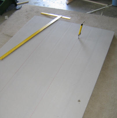
Cutting the R-Board insulation panels
that are used to insulate the tank. It cuts nicely with either a saw or a
long blade razor knife.
Cutting the R-Board insulation panels
in the shop before fitting them into the frame.
I think that 2 inch thick
polyisocyanurate (Atlas R-Board is one brand) is a good choice. It has
high temperature resistance, and a high R value per inch. It costs about
the same as the pink and blue extruded polystyrene, but has better R value and
temperature resistance.

I used aluminum tape to seal the
edges better for moisture penetration.

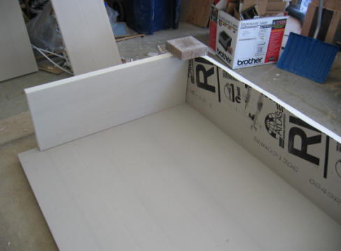
The insulation boards being fitted
into the pond frame.
I used "Great Stuff" polyurethane
foam in a can to both glue the panels to the walls in a few places, and to seal
any gaps between the panels.
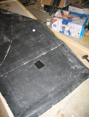
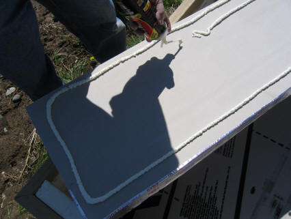
Liner:
The pond is lined with a single piece
of EPDM. Cut the piece to rough size. Remember that it for the
prototype it was about (41 + 14+14 +4 +4 + a bit more) = 80 inches
by (89 + 14 + 14 + 4 + 4 + a bit
more) = 127
Where 41 is the inside width, 14 is
the height, 4 is the thickness of the insulation board plus frame wall -- ad an
allowance to this just to be safe.
In my case I already had a piece of
EPDM that about 122 long, and I made this work by adding some wedge shaped
pieces of insulation board to the bottom corners .
You want the EPDM to extend all the
way to the outside of the frame boards, where it is attached
Cut the liner piece to size.
Mark the middle of each edge of the liner, and mark the middle of each edge of
the frame -- this makes it easier to install.
|
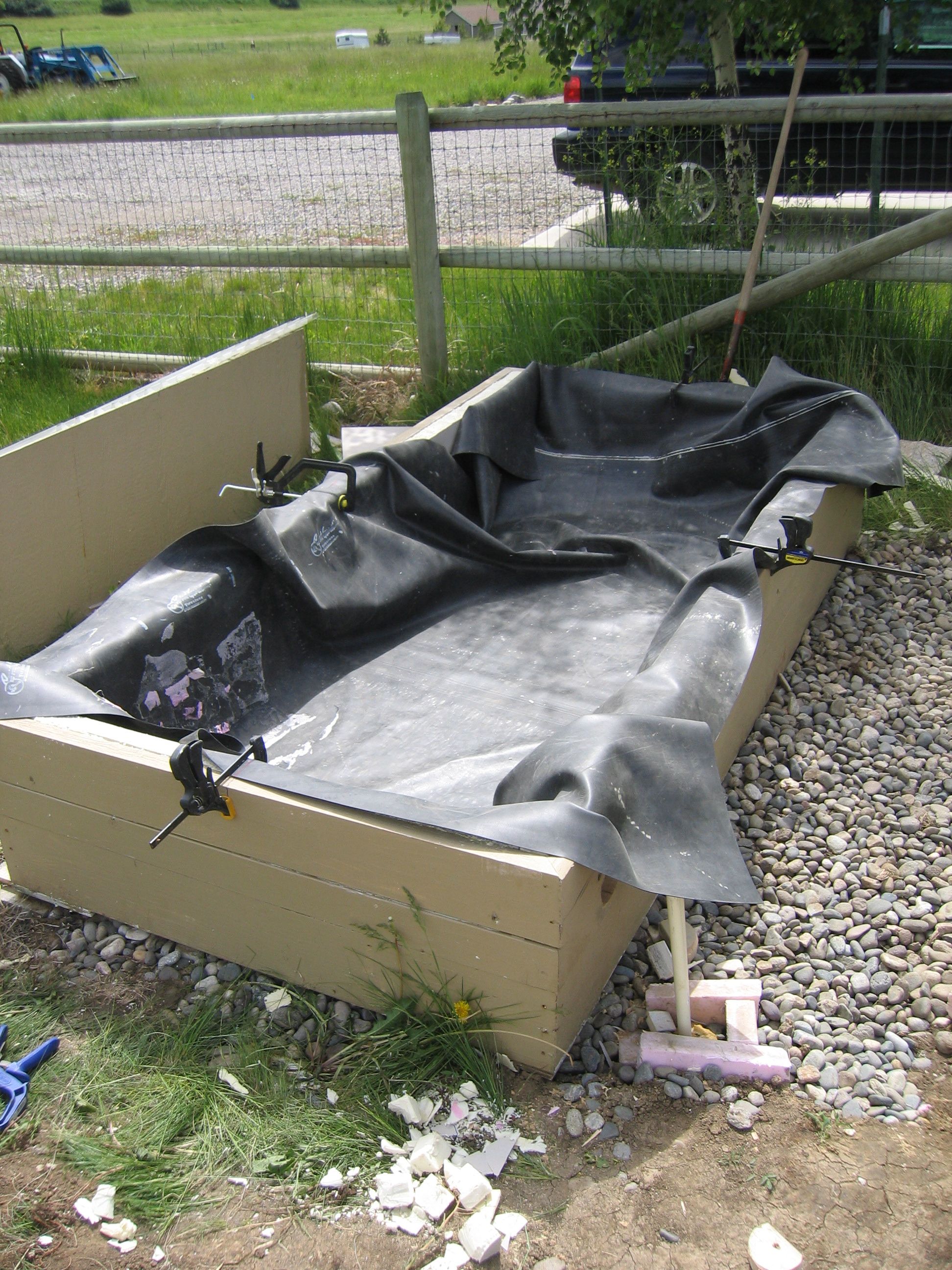 |
Using the middle marks to get the liner in the
right position. |
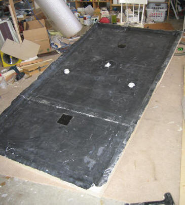
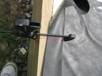
Install the liner -- clamp the middle
marks on the EPDM edges opposite the middle marks on the edge frames. Then
work the liner into the pond.
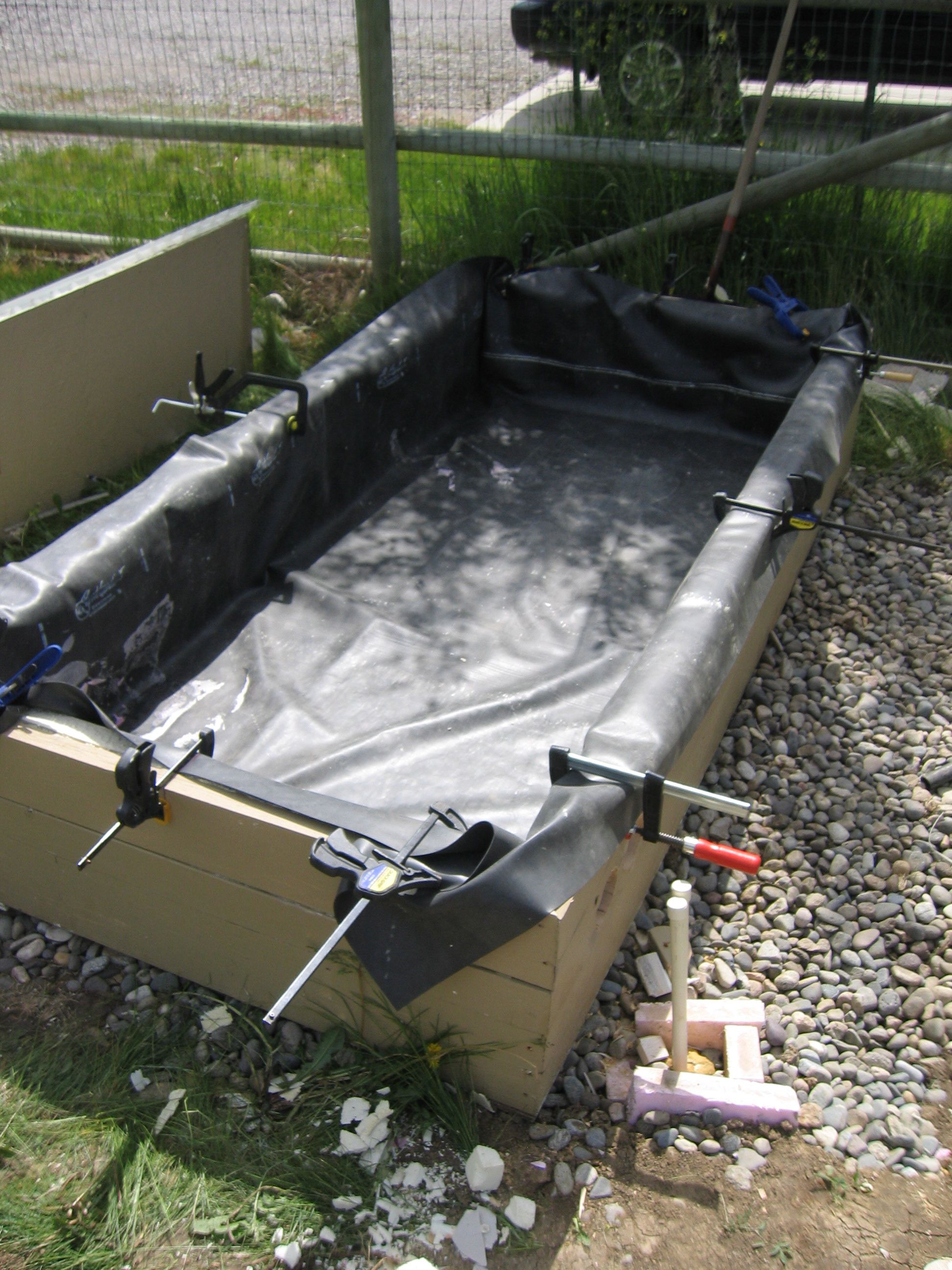
Work all the extra material into one
neat fold at each corner. Make sure that the liner is right up
against the insulation board everywhere -- you don't want it to be stretched
when the water is put in.
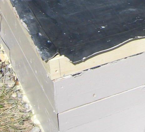
Once you get it to this point, you
can apply a bead of silicone between the liner and the frame, and then staple
the liner to the frame.
Note the two buried pipes coming up
next to the tank. These are the buried pipes to the house. After
everything is hooked up, this are will be boxed in with insulation (lots of it
where I live :) )
The pipe coil
For the prototype, I used two 100 ft
long coils of 1 inside diameter HDPE (High Density Polyethylene) that is NSF
approved. This is the commonly available black poly pipe that Home Centers
sell. Make sure it has the NSF label, as this assures that it is suitable
for drinking water. I used the lowest pressure rated pipe (100 psi) just
to see if this results in any problems, but I would recommend using the higher
pressure rated pipe.
One reason for using the two coils
is that it fits nicely into the pond. You don't have to fight with getting
it into a position it does not want to go into.
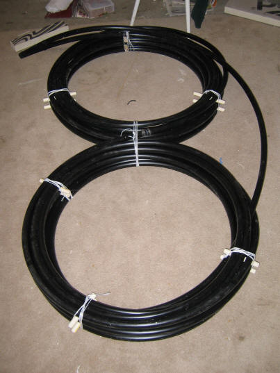
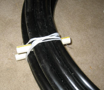
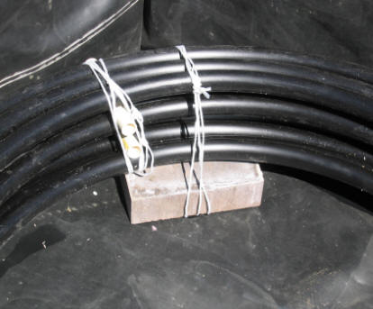
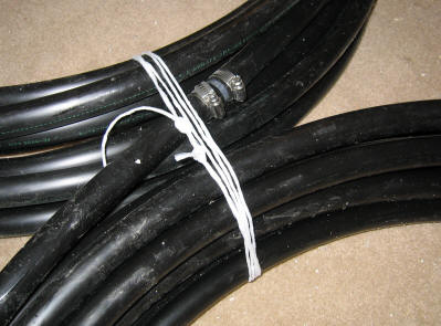
This shows the two coils laid out on
the floor and joined together. This is exactly the size coils they came
in. The right picture shows the short lengths of CPVC pipe to space
the pipe coils apart a bit for better heat transfer from the pond water to the
coils. I tied the coils with polypropylene twine.
The splice fitting that splices the
two coils together.
An alternative to the two 100 ft
coils would be to use one 300 ft coil. I believe that this would fit OK,
and it would hold somewhat more hot water in the pipe coil (12 gallons vs 8
gallons for the 200 ft). You would have to work out a way to spread
the coil out so that it occupies the full length of the pond -- its seems like
this might be doable. Remember that there must be a place for the pump
when you are done.
The Pipe Coil Connections
The pipe coil has to enter and exit
the pond. This means that they have to penetrate the pond liner. I
used two bulkhead fittings from our local AG store. I believe that
these are sold primarily to make connections through the walls of molded poly
tanks.
|
 |
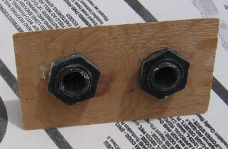
Back side of the bulkhead fittings. |
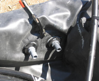
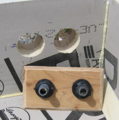
Shows the holes drilled in the pond
wall, the two bulkhead fittings (black), and the threaded to barbed adaptors
that adapt the poly pipe to the threaded bulkhead connectors. The
plywood goes behind the EPDM just to give the bulkhead fitting something
substantial to attach to, and to support the liner.
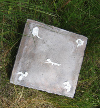
Coil Supports
The pipe coil should be spaced off
the bottom of the pond to allow for easier fluid convection around the coil, and
to place it in the hotter (top) part of the pond. I used concrete pavers
to space the coils off the bottom of the pond.
I put a few dabs of silicone on the
bottom of each paver just to keep it from abrading the lining.
I tied the coils down to the pavers
so that if the coils get a bit of air in them, the pavers will hold them down.
Note that the pavers will not hold down the coils if they are full of air,
so fill the coils with water before you fill the pond with water. I
drilled a hole in each paver to run the tie down string through, but this is
probably not necessary.
If you use something other than
pavers, be sure they will hold up to continuous exposure to hot water -- some
bricks won't.
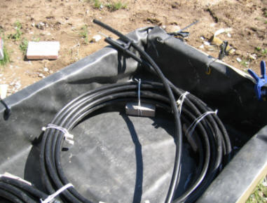
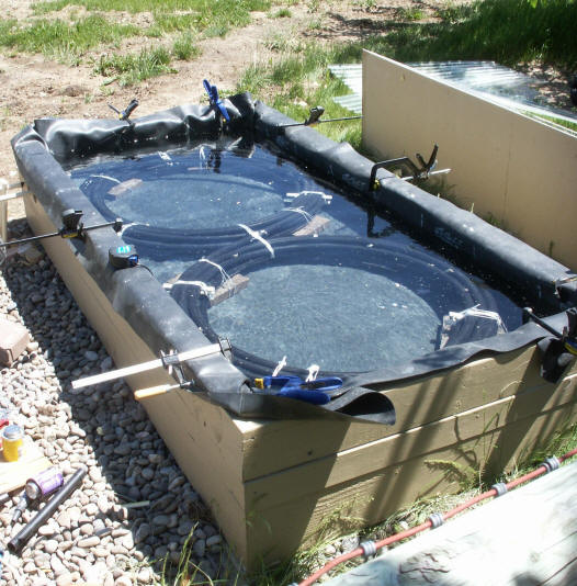
This shows the coils placed in the
pond with the inlet and outlet routed to where the bulkhead fittings will be
installed. Right picture shows the bulkhead fittings installed, and ready
to hook up to the pipe coils.
At this point, hook up the pipe coil
to the bulkhead fittings and fill the pipe coil with water under pressure.
Check very carefully for leaks before you fill the pond with water. The
leaks will be a lot harder to spot after they are underwater :)
Pipe coil installed, and pond filled
with water. Make sure that the liner is not stretched anywhere.
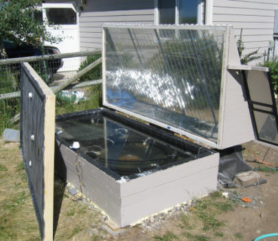
The cover structure
The cover structure
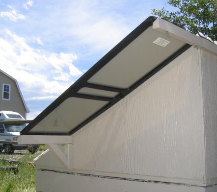
The first prototype had horizontal
glazing. This was a bad choice for two reasons, 1) the glazing got very
dirty very quickly -- it actually sagged just enough to develop mud puddles, and
2) while the horizontal glazing collects a lot of sun the the summer when the
sun is high, it is poor in the winter with the low sun. Building a
sloped glazed structure over the pond with reflectors on the north, east and
west walls helps to solve both problems.
If I had it to do again, I would make
the slope even steeper in order to improve winter collection -- possibly sloping
the top of the back wall toward the south some to allow more low angle sun to be
reflected into the absorber.
The cover consists of a light wood
frame that is covered by wood soffit material.
The wood frame.
The south edge of the cover should be
as thin as practical to avoid shading the pond when the sun is low.
The pipe coil in the background was
used in prototype 2.
The cover assembly with the wood
soffit board material sides attached. The wood soffit board a pressed
board material sold in 4X8 sheets, and comes with what appears to be a very
durable outdoor finish.
I applied a thin layer of insulation
and then reflectorized Mylar to the inside surfaces of the cover.
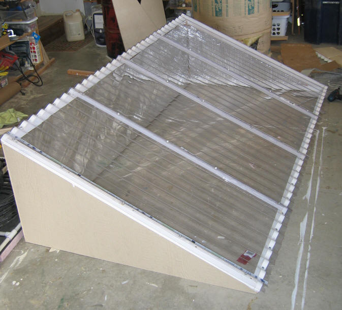
This shows the corrugated SunTuf
polycarbonate glazing in place. This is available at Home Centers for $1
per sqft. In this picture, the intermediate glazing supports (every 2 ft)
are wood strips, I later changed these to half inch EMT conduit, which I think
works better and is more rigid.
The inner glazing frame is screwed to
the bottom of this cover.
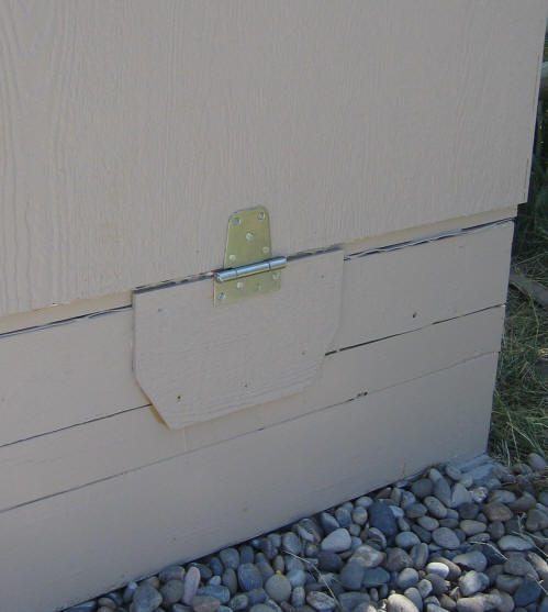
The cover is hinged to the pond frame
so that it can be opened easily for access to the top of the absorber and the
pond.
Absorber and cover installed.
The EPDM absorber has not been trimmed or attached to the edge frame as yet.
The inner glazing panel
There is a layer of Mylar film
glazing just above the absorber. This layer provides added R value and
prevents water vapor from getting up into the cover assembly. The Mylar
and its frame are screwed to the bottom of the cover such that when you hinge
the cover up, the Mylar glazing goes up with it -- this gives direct access to
top of the absorber surface.
The Mylar glazing film is attached to
a simple wood frame, which is then screwed to the bottom of the cover assembly.
The Mylar glazing and frame.
The right picture shows the detail of the corner of the frame and attachment of
the Mylar to the frame. Use a bead of silicone caulk all the way around.
The Absorber/Lid and pump
(updated 7/8/07 to show the new
absorber/lid arrangement).
The absorber/pond lid is made from a
piece of 2 inch thick R-Board polyiso insulation, and then covered with an EPDM
cover, which acts as the absorber. When the sun is shinning, pond water is
pumped on top of the EPDM, heats up, and then drains back into the pond.
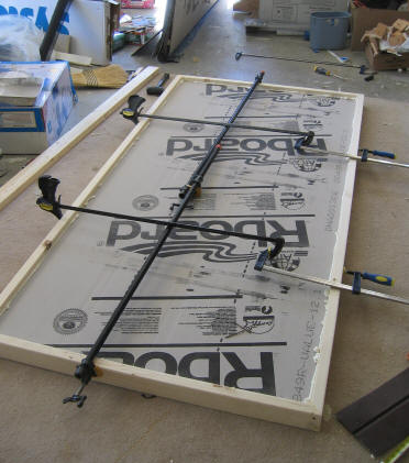
The insulated lid with its 2X4 frame.
The 2X4 frame sits directly on top of
the edge frame of the pond, and is screwed and sealed down to it.
The EPDM absorber goes over this lid.
The EPDM goes up over the edges of the 2X4s. The edges of the 2X4s extend
about 1 inch above the insulation board, and this is what makes the edges of the
shallow pond on top of the EPDM.
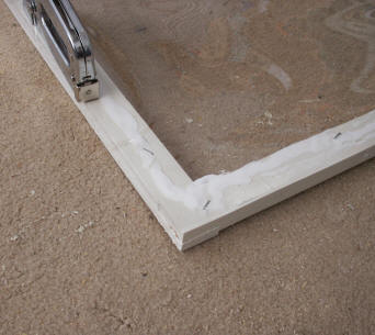
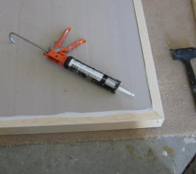
Corner joint.
The 2X4 edge frame is glued and
sealed to the 2 inch insulation board using Great Stuff polyurethane foam in a
can. You can just see little beads of it oozing out.
Bottom side is also sealed with
Silicone.
It might be a good idea to cover the
bottom with some form of water impervious layer that extends all the way out to
the outer edge of the 2X4s -- this would then give the water not access to any
of the insulation that surrounds the pond.
The lid has three penetrations.
-
The pump output line penetrates the
lid to move water from the pond to the top of the absorber.
-
There are two large drain pipes
that allow water that has been pumped on top the absorber to drain back into
the pond. These are set slightly above the level of the EPDM, so that
the pond has to be about a half inch deep before fluid can drain back.
This is to insure that the full lid is water covered. These are 1.5 inch
diameter PVC pipe siliconed into holes in the R Board.
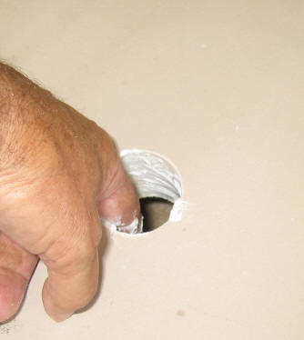
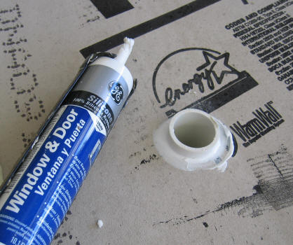
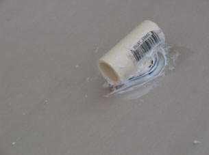
This is one of the two drain
penetrations through the insulation board. The drain pipe is 1.5 inch PVC
(probably too big). I sealed the insulation board inside the hole with
Silicone, then pushed fitting through, and sealed a fillet around the fitting
with Silicone.
The drain fitting sticks up above the
top of the board so that a shallow pond will form on top of the board so that
the water pumped up from the pond reaches all parts of the absorber.
The drain fittings should be long
enough so that on the underside of the lid, they extend below the pond water
level.
I later added saw cuts in the two
drain fittings on the top side. The saw cuts extended down to the level of
the EPDM. The idea was that after the pump shut off, the water remaining
on top of the lid would slowly drain down into the pond. This has turned
out to not work very well, and some other solution is needed.
The pump pipe comes up from below
into this CPVC T fitting. It is sealed in the same way as the drain
fittings described above. About 10 inches of rubber hose connects the pump
outlet to this T fitting. The connection from the rubber pipe to the T is
just a tight friction fit.
The EPDM liner being fitted over the
insulation board lid. Some Silicone is used to bond the EPDM to the
Insulation board and 2X4 frame. The wood blocks are convincing the EPDM to
make a fairly square corner where it comes off the insulation board and goes the
one inch up to the top of the 2X4.
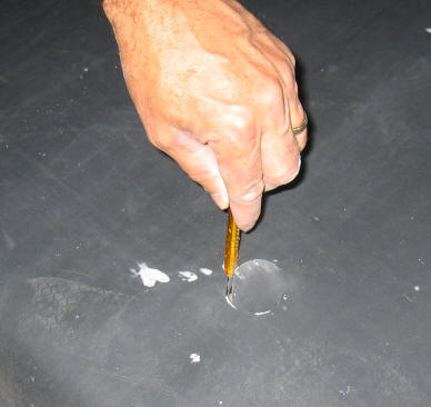
The hole being cut in the EPDM for
one of the drain fittings. The EPDM is just positioned over the drain
fitting, and a razor knife is used to cut the EPDM. Cut to the INSIDE of
the pipe, so that the EPDM must be pushed over the outside diameter and seals to
it well. Then seal with silicone.
Right picture shows the absorber and
insulation board lid ready to go.
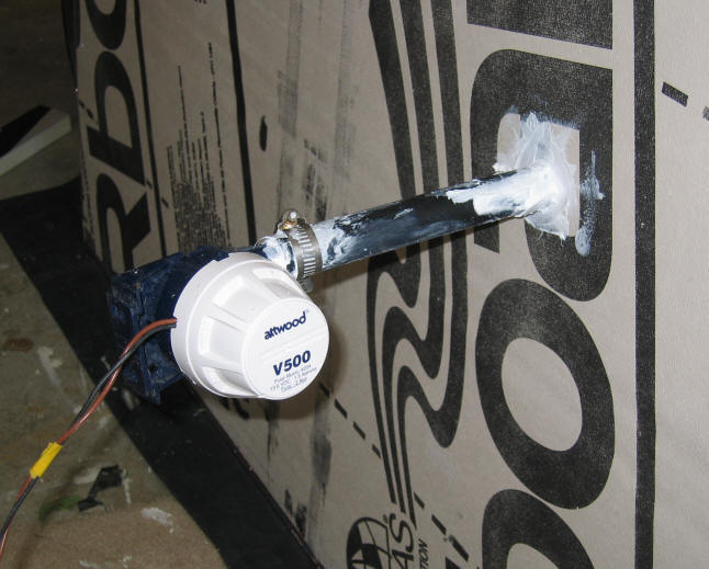
The Attwood submersible bilge pump
mounted to the R-Board lid. The hose is a flexible rubber hose. Down
is to the left. I do not expect this pump to have a very long life.
Any ideas on a good 12 volt DC, low current, about 2 gpm pump, that is not too
expensive?
left Picture shows the absorber/lid
assembly ready to mount on top of the pond frame. The 2X4 frame of the
absorber/lid mounts directly on top of the pond edge frame, and over the EPDM
pond liner.
The right picture shows the
absorber/lid assembly mounted on the pond edge frame.
Water being pumped out of the T
fitting that connects to the outlet of the PV driven pump.
Wire and blue tape are for the pump
outlet temperature sensor.
The PV panel
The 15 watt PV panel is mounted at
the side of, and attached to the cover assembly.
The PV panel is supported by some
wood supports that screw into the cover side and back. This panel may be a
bit larger than needed, but I had it on hand. Its an about 15 watt panel.
Connections:
Right now, the water heater is not
connected to the house plumbing. I want to first run it for a while with
carefully metered water draws to get an accurate idea what the performance is.
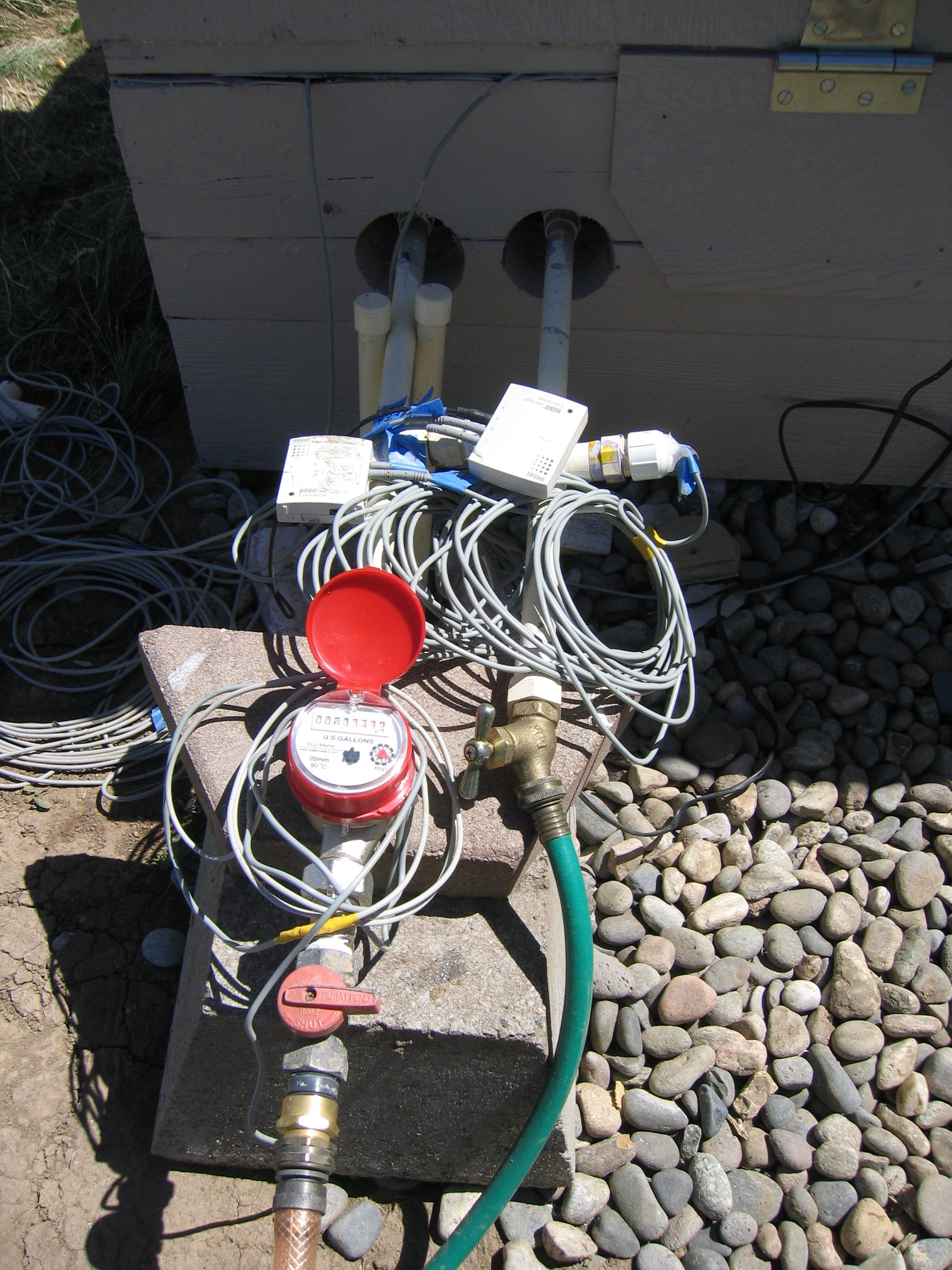
The current test setup. The
incoming cold water is the left connection with the red valve. This goes
through a water meter so that the size of water draws can be carefully
controlled.
The two white boxes are Onset
Computer data loggers. One logs the 1) pond temperature, 2) pump
outlet temperature, 3) absorber drain to tank temperature, and 4) solar
intensity (with an Apogee Pyranometer).
The second is used during draws, and
logs the pipe coil inlet and outlet temperatures and the pond temperature on 1
second intervals during the water draw.
Once the performance is better
understood, I'll hook up the pipe coil to the house plumbing and box in this
area with insulation. I believe that there will be enough heat loss along
the pipe from the pond to prevent any tendency to freeze when water is not used
for a long period of time.
Gary 6/25/07
revised 7/8/07