Downspout Test Collector Construction
This page details the construction of a solar air heating test collector
that uses gutter downspouts as the absorber. The downspouts are
laid out side by side to form the collector absorber. The downspouts are all
connected to air supply and return manifolds that run along the top and
bottom of the collector. Air is forced through the collector and picks up
heat from the sun heated gutters.
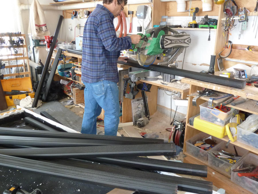
Here are some pictures of working downspout collectors from
Scott's
site...
The aim of building this test collector is to do a side by side
performance comparison with other solar air heating collector designs.
The collector box uses exactly the same construction as the
"Reference Collector", which is described in detail here...
The details below cover adding the downspout absorber and manifolds to the
basic box described in the Reference Collector. I'm not recommending
this as a design to build for the long haul -- see the end of page for some
things I would think about changing for a "production" design.
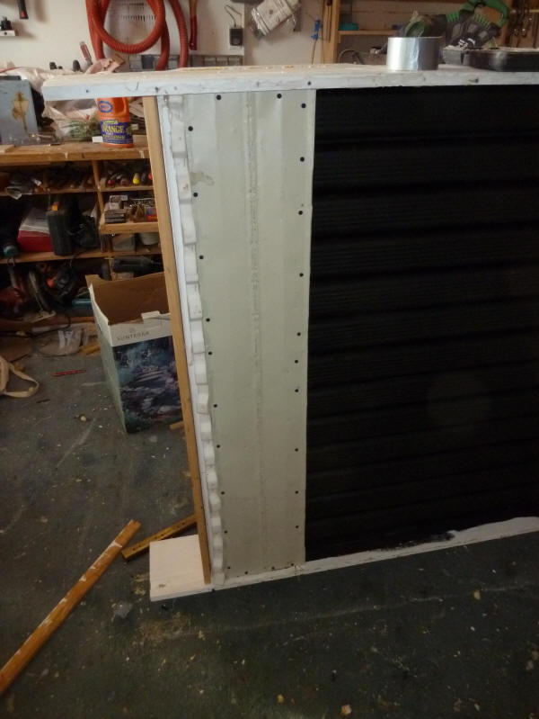
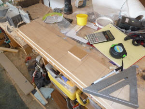
The depth of the collector box from the top surface of the insulation to
the bottom surface of the corrugated glazing is 4.5 inches.
Painting the downspouts |

Cutting the downspouts to length |

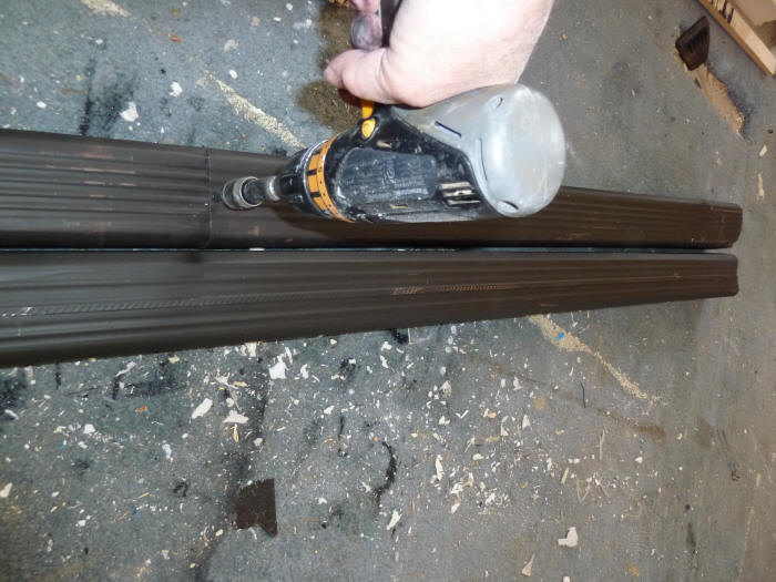
Splicing together the cutoffs to make
additional lengths.
Two of the cutoffs from the 10 ft
long gutter sections were just long enough
to make a full length section.
One is just slipped inside the other and
fastened with a couple short self taping screws.
A bead of silicone caulk was applied before
pushing the sections together. |
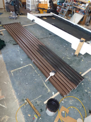
The downspouts used are from Lowes and are standard 2 by 3 inch aluminum
downspouts.
I spaced the downspouts about 3.5 inches apart -- this leaves only 0.5
inches between downspouts. I discussed with Scott several
alternative options for placing the downspouts, including 1) spacing the
downspouts further apart with aluminum sheet installed under the downspouts
to conduct solar heat into them for sun that hits between the spouts, 2)
flattening the downspouts to make them wider but not quite so tall --
this would reduce the number needed for a given width collector, and 3)
spacing the unaltered downspouts quite close to each other (as I ended up
doing). I think that approaches 1 and 2 above deserve a look, and may
be more cost effective, but I wanted to test the downspout collector design
that looked like it would have the best chance at being as efficient as a
downspout collector could be. The close spacing of the downspouts
gives the highest ratio of absorber area in contact the flowing air to area
that the sun shines on, and makes full use of the ability of the
downspouts to conduct solar heat around to the back side of the downspouts
to provide more heat transfer area. It is also the most expensive
approach in that more downspouts are needed for a given width of collector,
which is where the other two options may be better.
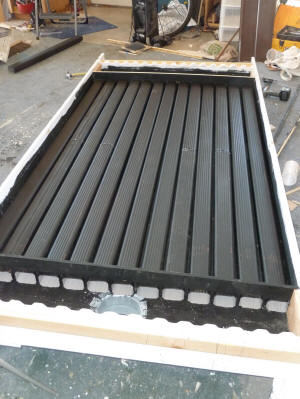
The collector takes 13 downspouts to cover the 47.25 inch inside width.
I bought nine of the 10 ft downspouts and was able to splice together the
cutoffs from the 9 to make a total of 13.
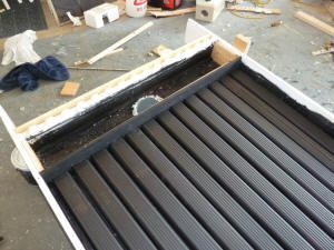
Manifolds
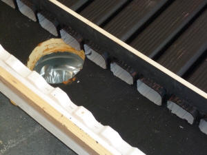
A 6 inch inlet duct goes into the bottom of the collector, and a 6 inch
exit duct leaves the top of the collector. A full width manifold
distributes air from the 6 inch duct to all of the downspouts, and a 2nd
manifold along the top picks up the air from all the downspouts.
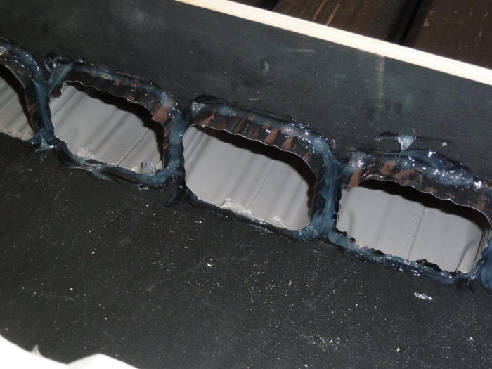
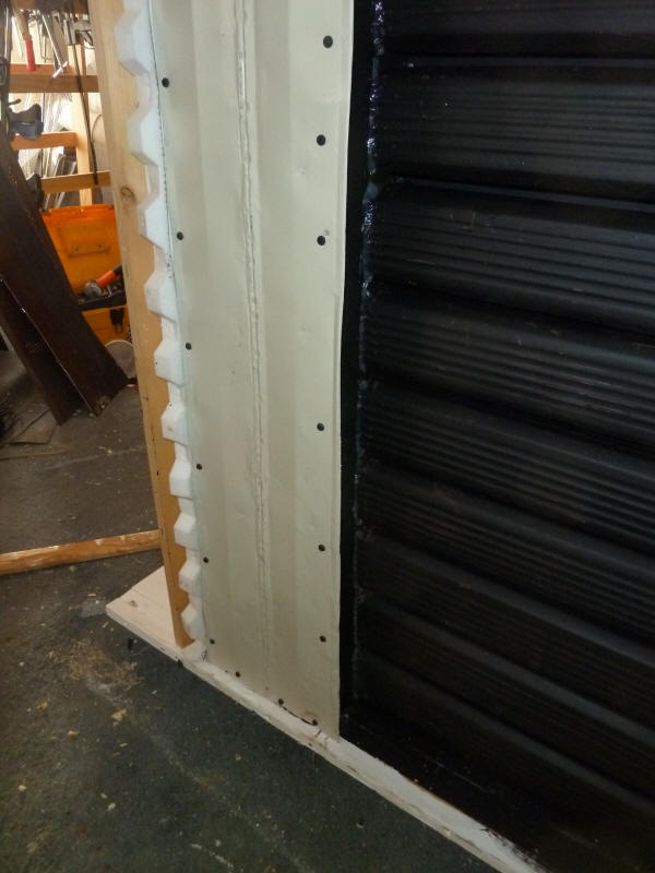
Half inch plywood with cutouts for the 13 downspouts were used to seal
the side of the manifold where the downspouts enter.
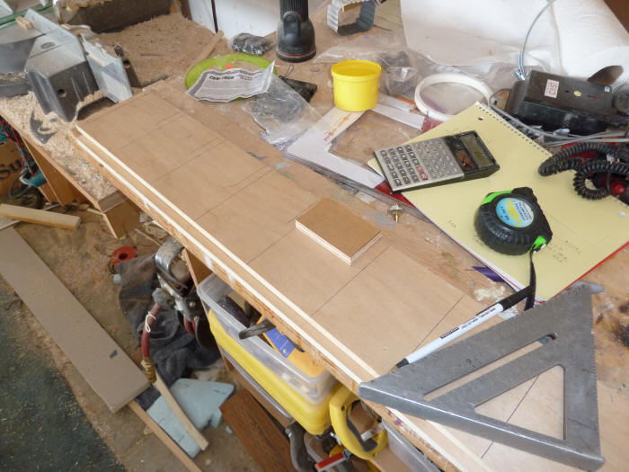
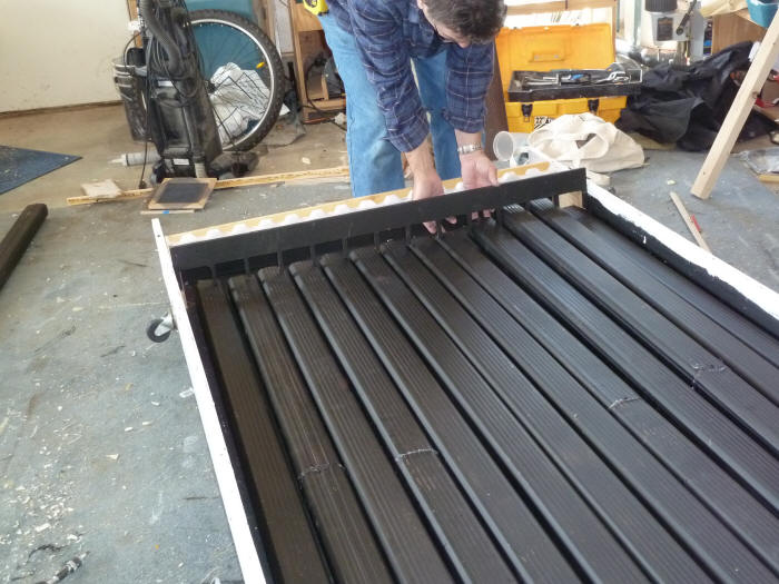
Laying out the downspout cutouts. |

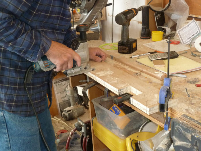
Cutting the openings for the downspouts. |
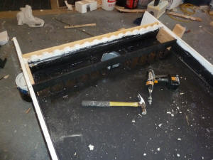
Installing the manifolds. |
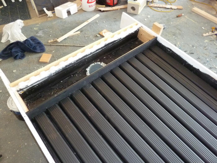
Note the two small blocks of plywood used on the ends of the manifold to
attach the downspout board to and also to attach the cover plate for the
manifold to.
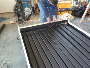
Its easier to pull the downspouts up into the
slots in the downspout board than
to put the board down onto the downspouts. |
downspout seal board in place. |
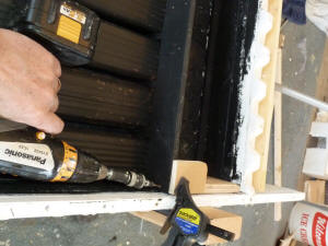
Clamp the downspout seal board down
tight so that it pushes the downspouts
against the insulation, then screw in place. |
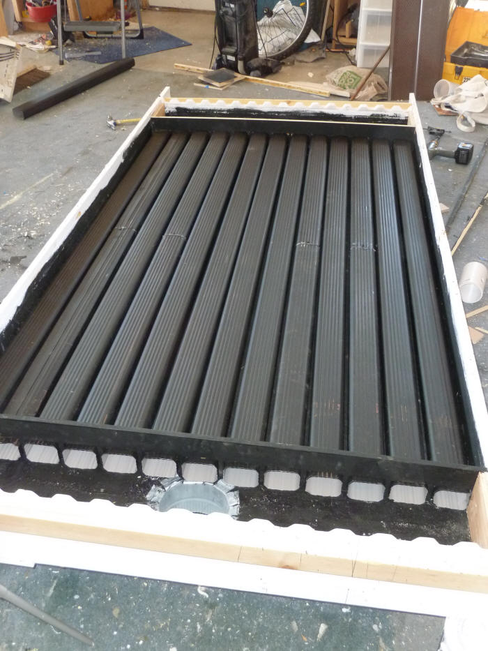
Some more views of
inlet duct entry and downspouts. |
downspouts installed. |
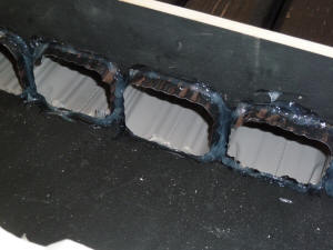
Sealing of downspouts to the downspout
seal board with silicone caulk. |

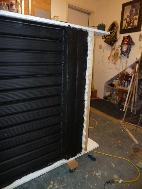
The aluminum manifold cover before
painting it black. |
 |
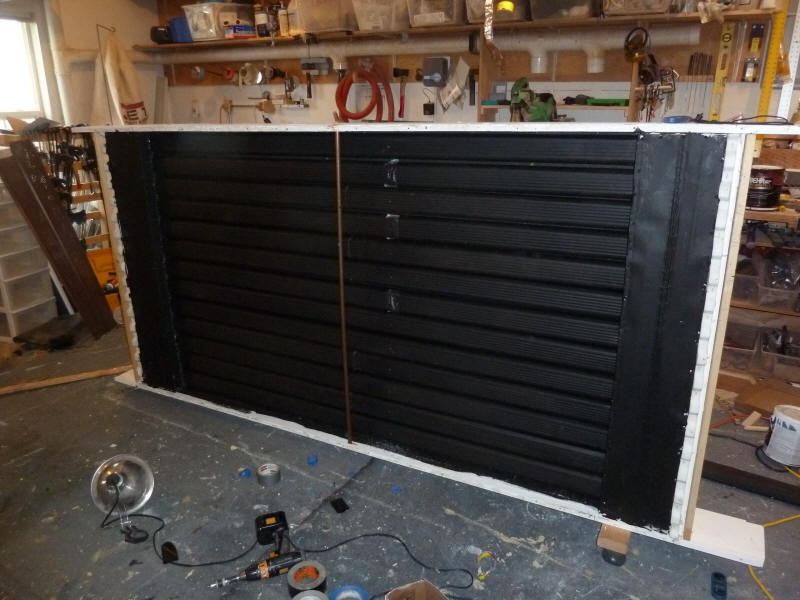
The manifold top (glazing side) cover is a single sheet of 0.018 inch
thick aluminum -- this allows the manifold areas to act at solar collectors.
In order to maximize the airflow area, the manifold covers are as close
to the glazing as possible without contacting it.

Finished collector without glazing.
The bumpy appearance of the manifold covers is
due to starting with grooved alum soffit material and
hammering it flat. |
 |
The manifold covers are sheet aluminum held in place with a lot of short
screws. I made them easy to open because I wanted to be able to make
changes inside the manifold, but they should be either sealed or
gasketed down to prevent air leaks.
The glazing is identical to the
reference collector...
The construction shown here is for a test collector, and is probably not
the best way to build one that you want to last for 30 years -- that said,
it does seem to work out pretty well. A couple changes that I would
want to be made is to pick a better joint at the top of the collector box to
exclude rain from entering, and pick a water resistant material for the
board that the downspouts penetrate to get into the manifold so that if
there is any condensation in the collector it will hold up better.
Gary May 3, 2011