Thermal Camera Examples and Lessons Learned (so
far)
Thermal (IR) cameras have been coming down in price over the past few years,
and just recently took another pretty good dip -- this last drop was enough to make me take the
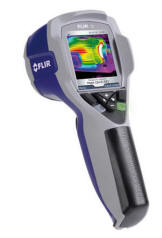
plunge and buy one. The camera I bought is made by FLIR. FLIR now offers entry level thermal cameras in
its I series. The entry level I3 goes for $1200, and the I7 that I bought is
$2000. The main difference in the I series camera models is the resolution --
the I3 is 60 by 60 and the I7 is 120 by 120. This may seem like pitiful
resolution compared to regular digital cameras that well up over 3000 by 2000
resolution, but even 60 by 60 resolution is like being able to place 3600
thermocouples on the object you are studying -- its pretty impressive and will tell you
things that are very hard to learn any other way.
My guess is that thermal cameras are likely fall significantly more in price.
I think they are in the process of going from a tool used by a few specialist to a
much more general use instrument that will be find its way into a lot of tool boxes.
One of the FLIR docs mentions that the TOTAL sales to date of their IR cameras
is only about 40,000 cameras -- practically
nothing compared to the number of people who could make good use of these
cameras.
This page goes over some first impressions, some surprises, some
potential uses, some basics on using an IR camera, and a few sample pictures.
Some IR camera references are also listed. This may help you decide if there is a thermal camera in your future.
I need
to mention that I have only had the camera for a couple months, and I'm still
learning. And, I've not even started to look at some of the major
application areas I have in mind -- like a detailed examination of my house for
heat leaks.
What A Thermal Camera Does
A thermal camera measures IR (heat) radiation from objects in its field of
view. A camera like mine with 120 by 120 resolution takes 120*120 =
14400 IR radiation readings over its field of view. The software in
the camera uses the IR radiation levels and your estimate of the emissivity of
the surface of the object and a few other things to estimate the surface
temperatures of the object. The camera software then maps the
temperatures into a color range for display. In the picture below, hotter temps
are shown in a whitish yellow-orange and cooler temps in dark blues.
Software that comes with the camera can be used to refine the images, change
the thermal range that is shown, show actual temperatures at any point, and
export the estimated temperatures for all or part of the image to an external
file that is spreadsheet compatible for further analysis.
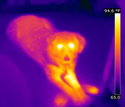
Kristy the dog.
Some important things to note about thermal imaging cameras.
-
Thermal cameras don't directly measure temperatures.
They estimate temperatures based on IR radiation, emissivity of the object,
and other factors. It is fairly easy to fool the camera into
giving you bad temperature estimates if you are not careful about emissivity
estimates (and a some other issues) -- see below. Luckily, the
emissivity of real world objects is such that useful temperature estimates
can usually be made (see below).
-
Thermal cameras give you the surface temperature of
the object -- they cannot see into the object. It can often look like
you are seeing into a wall or floor, but what you are really seeing is the
influence that a hot or cold element within the wall has on the surface
temperature of the wall. See the heat spreader plate images below as
an example.
-
The thermal color images like the one above have very
little meaning unless the temperature scale used to produce the image is
also provided. In the case of the image above, the temperature scale
is on the right and goes from 65F up to 94.6F and it show the color that
maps to all these temperatures. The exact same image can look very
different if the temperature range is changed. So, if you are looking
at an thermal image, always be sure to have the thermal range that was used
to produce the image, and make sure that the range makes sense for the parts
of the image you are looking at. The software that comes with the
camera can be used to fine tune the temperature range for the pictures.
-
Things that are transparent in the visible light
world are not necessarily transparent in the IR world and vice versa.
For example window glazing is transparent in visible light, but nearly
opaque in IR light -- so, if you take an IR image "through" a window, what
you are really getting is the surface temperature of the window glazing, not
the temperatures of the stuff on the other side of the window.
Some things that are opaque to visible light are fairly transparent to IR --
black poly film form instance.
-
IR radiation can be reflected just as visible
radiation is reflected. Shiny metals reflect IR quite well. This
can be a problem in that if there are reflections in the thermal image, then
what you are getting for those reflection areas is the temperature of the
object being reflected and not the temperature of the object you want.
You can actually see and identify these reflections if you look for them,
but they are easy to overlook if you are not careful.
Some Example Pictures
Below are a few interesting (at least to me) thermal image examples.
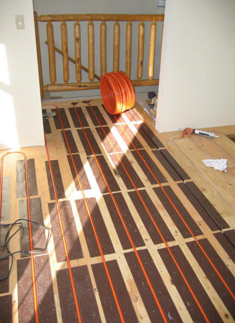
Radiant floor heat spreader plates
I used these heat spreader plates in my radiant floor heating system:
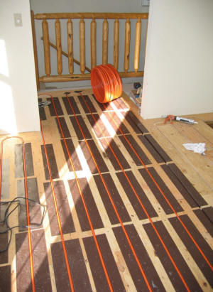
Spreader plates being installed -- a wood finished floor goes over these plates.
The heat spreader plates are supposed to increase the effectiveness of the
radiant floor heating tubes by conducting heat from the tubes out over much
wider area. This is supposed to both increase efficiency by reducing the
water temperature for a given heat output and to reduce the variation in
temperature over the floor, avoiding hot spots.
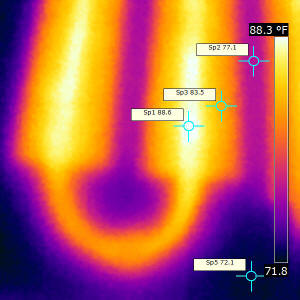
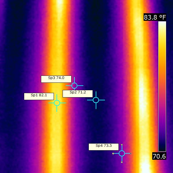
Floor with the heat spreader plates. |

Two tubes in a floor section without the
spreader plates. |
While you can delve into it further with the camera software, its pretty
clear from the picture that the heat spreader plates are resulting in a much
wider area of pretty uniform high temperatures.
Note that while the picture makes it look like you are looking through floor
to the spread plate below the flooring, what you are actually seeing is the
surface temperatures on the top of the finished floor which are warmer because of the hot
spreader plate below the floor. This is generally the case -- the IR
camera normally sees the temperatures of the nearest surface in front of the
camera -- when it looks like you are seeing through the first surface to
something behind (for example a cold pipe inside a wall) what you are really
seeing is the cooling or warming effect of the hidden object on the temperatures
of the first surface. The exception to this would be if the first surface
is transparent to IR -- for example polyethylene film.
Thermal Physics of the Stuff Around Us
One of the interesting things about the thermal camera is that it seeing
images of everyday things in temperatures really makes you think about
what's going on to cause those temperatures.
The water storage tank below shows one simple example. The top part
of the tank in the sun has little mass and warms up quickly while the bottom
half filled with water changes temperature very slowly. What would the
picture look like if you took it early on a cold morning before the sun was
on the tank?
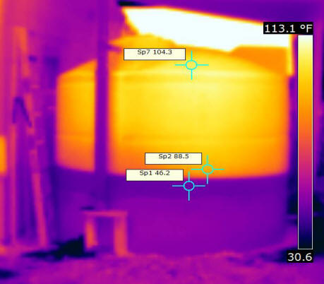
Thermal image of our new 2200 gallon gallon rain water collection
tank.
Very easy to see the level of the water in the tank. |
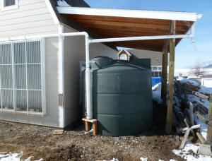
The rainwater collection tank. |
I'm not suggesting its worth buying a thermal imaging camera for measuring liquid
levels in tanks, but its interesting to see the different view of
the world you get when you look at it in temperatures rather than visible light.
These cameras would make great tools for school Physics classes.
Solar Collectors
 The
main reason I got the camera was to try to get a better idea what the is going
on in some of the solar collector designs I'm looking at. Its hard to see
what might improve a collector if you can't figure out what the flow and
temperatures are really like in the design you are starting with.
The
main reason I got the camera was to try to get a better idea what the is going
on in some of the solar collector designs I'm looking at. Its hard to see
what might improve a collector if you can't figure out what the flow and
temperatures are really like in the design you are starting with.
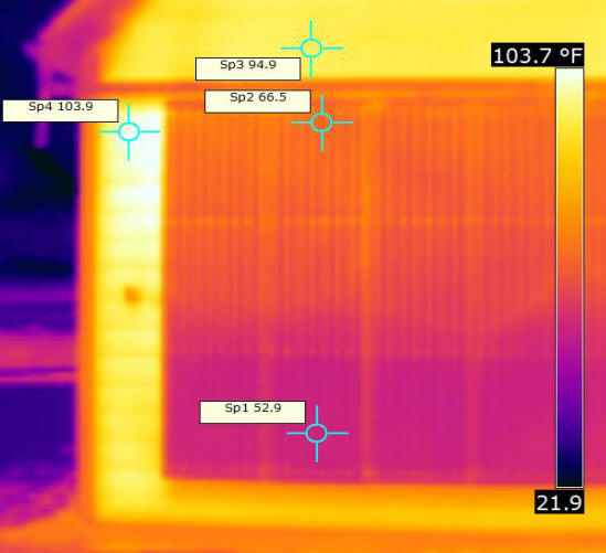
The picture to the right shows a thermal image of my
shop solar air heating collector with the sun shining on it. You might
expect the collector to be hotter than the surrounding wall, but its actually
quite a bit cooler -- why?
The wall next to the collector is hot (roughly 100F) because even though the siding is a fairly
light color its solar absorptivity is pretty high. So, a lot of the
sunlight is absorbed by the wall and heats it up. Inside the collector,
the absorber is likely even hotter than the wall because its quite absorbent,
but the camera does not see the absorber, it sees the temperatures of the
surface of the collector glazing. The collector glazing is cool because it
lets nearly all of the solar energy through to the absorber. So, the
glazing runs at a temperature that is more influenced by the contact with the
outside air and the heat it picks up from the absorber and the air inside the
collector.
Note that the glazing does get warmer as you go up the collector --this is
likely due to the collector absorber being warmer near the top and transferring
more heat to the glazing.
One of the marks of a good solar collector is that the glazing runs fairly
cool -- hot glazing means that the lots of heat that should be going to the room
is instead being lost out the glazing to the outside air. So, this
relatively cool glazing is a good thing.

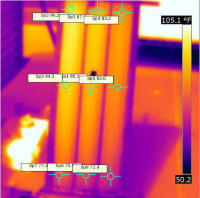
The
picture to the right is a thermal image of a
backpass solar air heating
collector I made to compare to other collector designs. The two actual
pictures below show the inside and outside of the collector.
In this type of collector, the sun shines on the front of the metal absorber
plate and heat is. Air flows only behind the metal plate and picks up heat
from the plate.
To try to get an even flow of air over the full absorber, internal
baffles are used to make the air flow down the collector from the inlet on
the top left along a back and forth curved path to the outlet on the bottom
right.
As can be seen from the image, the baffles have not been fully successful in
getting even airflow over the full absorber surface. There are hot spots
on the absorber that indicate dead air pockets that are not getting enough air
circulation to remove the heat from the absorber. This is bad in that
these hot sections of absorber lose a lot of heat out the front of the
collector.
To me, this is one of the areas where the IR camera really shines -- it would
be very difficult to get this kind of picture of what is going on in the
collector with any other technique I know of.
Note that this test has to be done with the collector glazing removed, or the
thermal camera would just get the temperatures of the glazing and not the
absorber. Another alternative is to use polyethylene film for the glazing
in that it is fairly transparent to IR radiation.
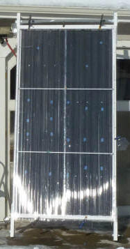
Prototype backpass collector |
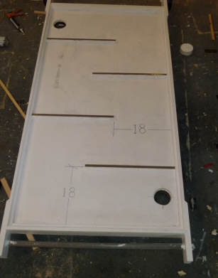
Backpass collector showing internal airflow baffles (black).
The metal absorber plate goes directly over these baffles. |
Downspout Collector Test
 There
has been an ongoing question on the
Yahoo
Simply Solar discussion group about how much solar heat gets transferred
around to the back surface of the solar air heating collectors made from gutter
downspouts. If a significant amount of solar heat gets transferred around to the
back so that the back, front and sides of the downspout collector are all hot,
then this increases the absorber to air heat transfer area, which is a major
consideration on solar air heating collector.
There
has been an ongoing question on the
Yahoo
Simply Solar discussion group about how much solar heat gets transferred
around to the back surface of the solar air heating collectors made from gutter
downspouts. If a significant amount of solar heat gets transferred around to the
back so that the back, front and sides of the downspout collector are all hot,
then this increases the absorber to air heat transfer area, which is a major
consideration on solar air heating collector.
In the downspout collector design, ordinary aluminum downspouts are laid side
by side (or sometimes spaced apart a bit) to form the absorber. Sun shines on
one side of the downspout heating it up. Air is forced through the downspouts
and picks up heat from the hot downspout metal and delivers it to the house.
If you want to see what a downspout collector looks like -- there are a
couple good examples on
Scott's
site... And, here is the
prototype full
size downspout collector that I did...
One of the difficult design issues with solar air heating collectors is
providing good heat transfer between the solar heated absorber and the air. Air
is light in weight and low in heat capacity, so a lot of air needs to be passed
through an air heating collector, and it has to be done in a way that puts a lot
of the air in good thermal contact with the absorber. Downspouts are thought to
have an advantage here in that they provide a large heat transfer area from
absorber to air. But, this is only true if the solar heat gets transferred
around the downspout sides and back. This test is aimed at finding out how well
the downspout does in transferring heat around to the sides and back.
This little test used the thermal camera to take images of the front and back
of the operating downspout collector to see how well the heat was transferred
around to the back of the collector. While a simple IR thermometer could
be used to get a fairly good idea of temperatures around the downspout, the
camera gives you a better view that is less subject to missing something.
All the details on the
downspout solar collector test are here...
Material Emissivity
The thermal camera actually measures the IR radiation from the object and not
the temperature. To go from IR radiation to temperature, the camera needs
to know the emissivity of the object. Its up to you to estimate the
emissivity of the object and to set the camera accordingly -- if you don't set the
emissivity correctly, the temperatures the camera shows will be wrong.
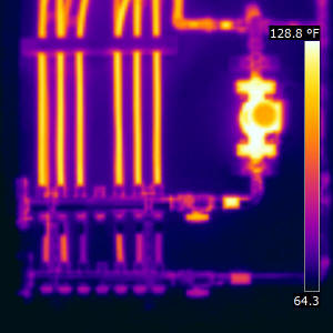 |
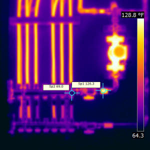
False temperature readings on manifold. |
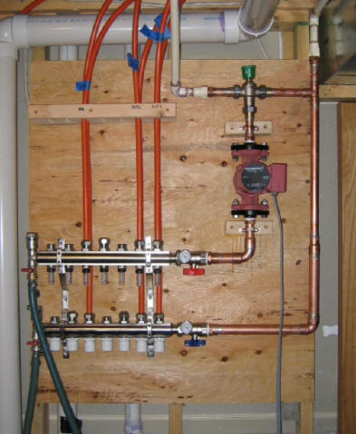
The thermal images above shown above are of my radiant floor manifold area
where all of the floor heating loops originate (see actual photo below).
The emissivity on the camera is set 0.95 for these pictures.
The manifolds are made from brass and the pipes coming into the two
manifolds are copper. Copper actually has an emissivity of anywhere
from 0.05 (polished) up to about 0.8 (oxidized) -- so, the camera emissivity
setting is way off for these bare pipes.
If you look at the thermal images of the two copper pipes coming into the manifold from the right
you will see a bright spot in each. The bright spot is a piece of painters
tape wrapped around the pipe. The emissivity of the tape is about 0.95, so
the temperature reading on the tape is a true one. The pipe right next to
the tape is, of course, the same temperature as the tape, but shows a much lower
temperature because the emissivity setting is not correct for the bare pipes.
The right picture is the same with temperature labels on the tape showing 126F
and on the pipe near the tape showing 69F. So, setting the wrong
emissivity in this case results in a very large error in the temperature
measurement on the pipes.
This is something that must be kept in mind all the time when using the
thermal camera. Luckily, many materials have an emissivity in the
0.9 to 0.95, and just setting this emissivity can bring good results on
many scenes. But, any kind of bare metal is likely to have a much
different emissivity, and trying to read the temperatures of bare metals
requires setting the emissivity correctly. In many cases the emissivity of
a bare metal will vary over a wide range depending on the surface condition of
the metal -- it may not be possible to accurately measure the temperature of a
lot of bare metal surfaces because you can't accurately estimate the emissivity
of the surface. Possible solutions in these cases are to put tape or paint of know
emissivity on the surface, or to measure nearby surfaces that are at the same
temperature and have a know emissivity.
Glass is another interesting material. It is, of course, transparent to
visible light, but in the IR, it has an emissivity of 0.97 and is essentially
opaque in the IR. So, if you take a thermal picture "through" a window
your are actually "seeing" the surface temperature on the glass, and not objects
on the other side of the window.
List of emissivity of materials:
http://www.infrared-thermography.com/material.htm and
http://www.thermoworks.com/emissivity_table.html
The Software
The software that FLIR provides with the camera is straight forward to use
and includes a number of useful features.
You can adjust the temperature range for the image, chose from a variety of
temperature to color schemes, adjust the emissivity used to calculate object
temperatures, move a cursor around to read the actual temperatures at any point,
add temperature labels to any point, and add notes or comments to document the
images.
There are also some tools that can help with preparing reports for customers
that I have not looked at.
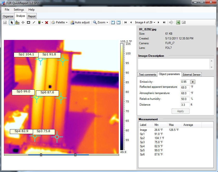
Screen shot for the FLIR camera software -- this is of a small prototype of the
"downspout" solar air heating collector.
"Review"
I'm not really qualified to review the FLIR I7 that I bought as its the first
IR camera I have owned and I've no real basis for comparison, but, I'll pass on
a few impressions.
The camera itself appears to be well made and fairly rugged. It comes
with a good case that holds the camera and charger etc. and protects them
well. The mechanical design of the camera tends to protect both the lens
and the display, and the lens has a nice built in shutter that can be closed
when not taking pictures for further protection.
The camera is very easy to use -- its basically like a very simple point and shoot
digital camera. Of course, as pointed out above, there are several
ways to get images that result in inaccurate temperature readings, and its
important to understand how the camera works and how to avoid the pitfalls.
An on display menu system is used to change the camera settings and it is
generally straight forward to use.
Battery life is somewhat limited but certainly adequate once you know are
aware of the issue.
The camera comes with a fairly extensive manual that covers both the
operation of the camera and some material on how to use a thermal imaging
camera.
The display is easy to read, but does tend to wash out in bright sun.
I've found this to be not so important in that the camera appears to save the
raw radiation data, and everything can be fine tuned and optimized in the
software. That is, the software allows you to change emissivity,
temperature range, color scheme, ... so, its not so important to get them
right on when taking the picture.
The warrantee is for 2 years, and I've not seen any complaints about FLIR not
being good about honoring claims. There is a website that provides some
helpful material and there is a forum for FLIR camera owners.
References
A nice thermal imager list of applications with examples...
A good book to start with: Introduction to Thermography Principles, from Fluke and the Snell
Group (available from Amazon etc.)
FLIR website...
FLIR manuals and datasheets...
Fluke thermal imagers...
Gary April 29, 2011