Off The Shelf Solar DHW -- Cheap and
Easy DIY Solar Water Heating
Update October 1, 2012:
This page covers the first attempt at the Off The Shelf Solar
DHW system.
I've done a bit of a reset on this, and
this page covers the newer version of the system. The
change is to go to a vertically oriented 4 by 10 collector
installed at a steeper tilt.
The reasons for this are explained on the new page -- they just
represent a move to a very similar system that I think will work
better than the one described below.
So, I consider this page to be obsolete, but I leave it here
because there is some useful information that does not appear on
the new page.
Gary
This project is a go at an inexpensive DIY solar water heating system
that is also easy to build. While the system is
inexpensive and easy to build its not cheap in the sense of low quality
-- I believe that its life and performance will be similar to commercial
systems.
Our $1K DIY Solar Water Heating system
has been a popular project and has been built successfully by a lot of
people. It is about one eighth the cost of a typical installed commercial solar water
heating system, and that's nice. But, it requires you
to build the collector and the solar heat storage tank yourself. While
building the tank and collector are fun projects, it does take some time and
is a bit more
that some people want to tackle.
This new system is aimed at using all off the
shelf components while still keeping the cost down. So, the
project becomes one of mounting the components and hooking them
together. Since the design is very simple, the hooking the pieces
together is a pretty straight forward job.
I'm in the middle of building the prototype and would like to hear any
comments or ideas for improving the design that you might have.
comments....
Think of it as an open source solar water heating project.
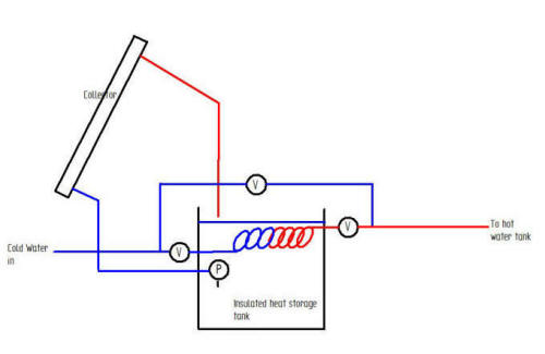
Overview
The system is a simple drain back design that uses a large, non-pressurized
tank for both the solar heat storage and as the collector drain back tank.
The pump (P) pumps water from the bottom of the large storage tank, up through
the collector to be heated, and then back to the top of the storage tank.
Incoming cold water from the street passes through the large pipe coil immersed
in the storage tank and is heated by the hot storage tank water before it gets
to your existing hot water tank. The three valves provide for bypassing
and isolating the solar tank for maintenance. There is a controller (not
shown in the diagram) that turns the pump on only when the collector is hotter
than the storage tank water. Your existing hot water tank provides
backup water heating when there is not enough solar heating. Freeze
protection is provided by the fact that the water in the collector loop drains
back to the tank when the pump turns off
The system design is actually the same as the $1K Solar Water Heater. The
difference is that all of the components for this system (tank, collector, pump,
and controller) are off the shelf items that you just buy. You just
mount the components and hook them up.
Components:
Collector -- The system uses unglazed plastic matt style pool heating
collectors.
Tank -- The solar storage and drain back tank is the SofTank from American Solar
Technics.
Controller -- The controller is the SR208C sold by Sun-Pump.com.
Pump -- The pump on the prototype is the Grundfos 15-58 3 speed HVAC circulator
pump.
Other than some plumbing, valves and a little wire, that is the whole system.
See the discussion below for the pros and cons of these component choices.
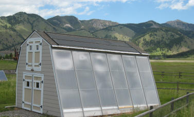
The Prototype
I'm building the prototype on my
Solar Shed using the roof above the existing water
heating collectors. The prototype is just being built to see how the
system works -- I plan to take it down after getting (at most) a years worth of
performance. Since the system is not hooked up to our house, the daily hot
water demand will be simulated.
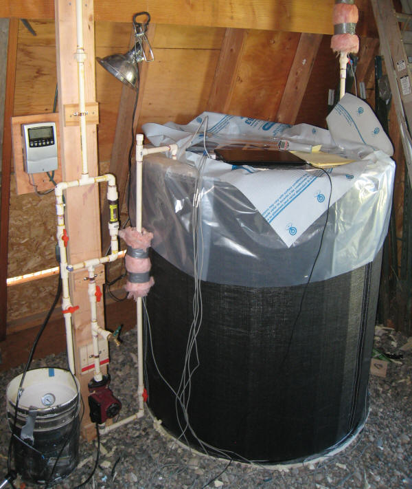
The prototype tank, controller and pump before finishing touches.
Setup for logging performance.
Collectors
Pros and Cons
The collectors are standard Fafco Sungrabber pool heating collectors bought
on ebay.
The pros and cons (I think) for these matt style collectors are:
Pros:
Low cost (less than 1/10th the cost per square foot of glazed commercial
collectors)
Good performance in three seasons.
Easy to install (light weight with simple mounting)
It is cheap to provide an excess of collector area to help make up for
poor cold weather performance.
Qualifies for most tax credit and rebate programs because the collector
is SRCC certified.
Cons:
Poor cold weather performance (see below for possible partial remedy)
Shorter life (15 to 20 years?) -- but, easy to replace.
Some pictures just below showing the mounting of the collectors on the Solar
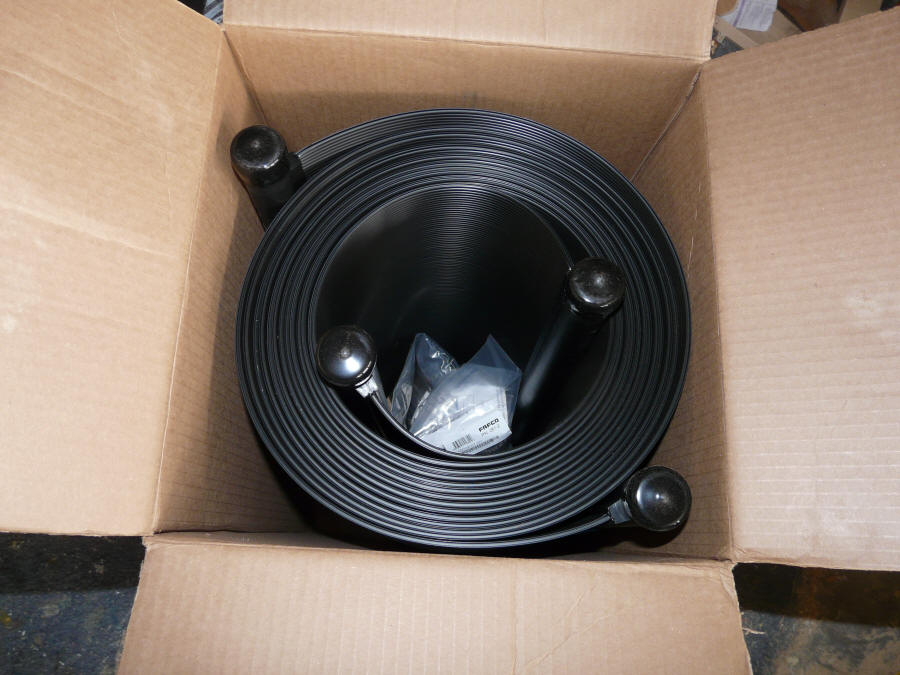
Shed roof.
This is 80 sqft of collector plus the mounting hardware.
One small UPS able box.
Contrast this to $200ish truck freight for a glazed flat plate collector.
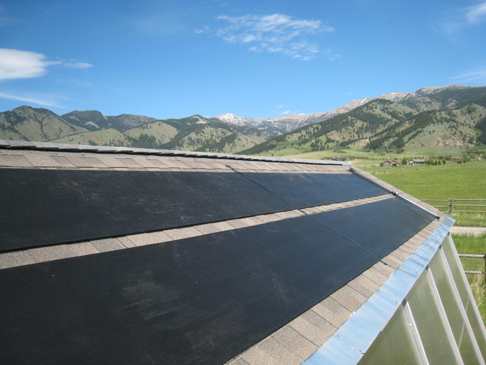
The two 2 ft by 20 ft collectors laid out on
the Solar Shed Roof.
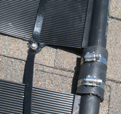
The straps are used to mount the
collectors -- screwed into the roof using
stainless steel screws and polyurethane
based roofing cement.
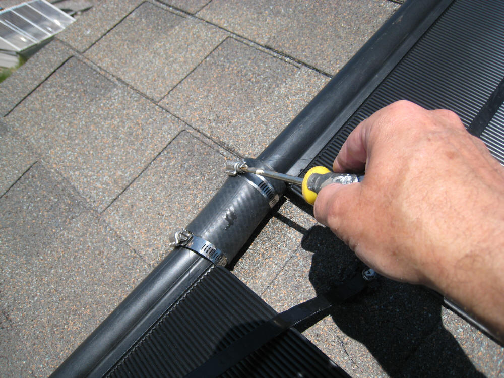
The collectors are coupled together using
provided rubber hose and the standard
worm screw type hose clamps.
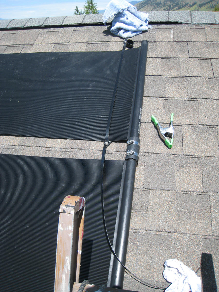
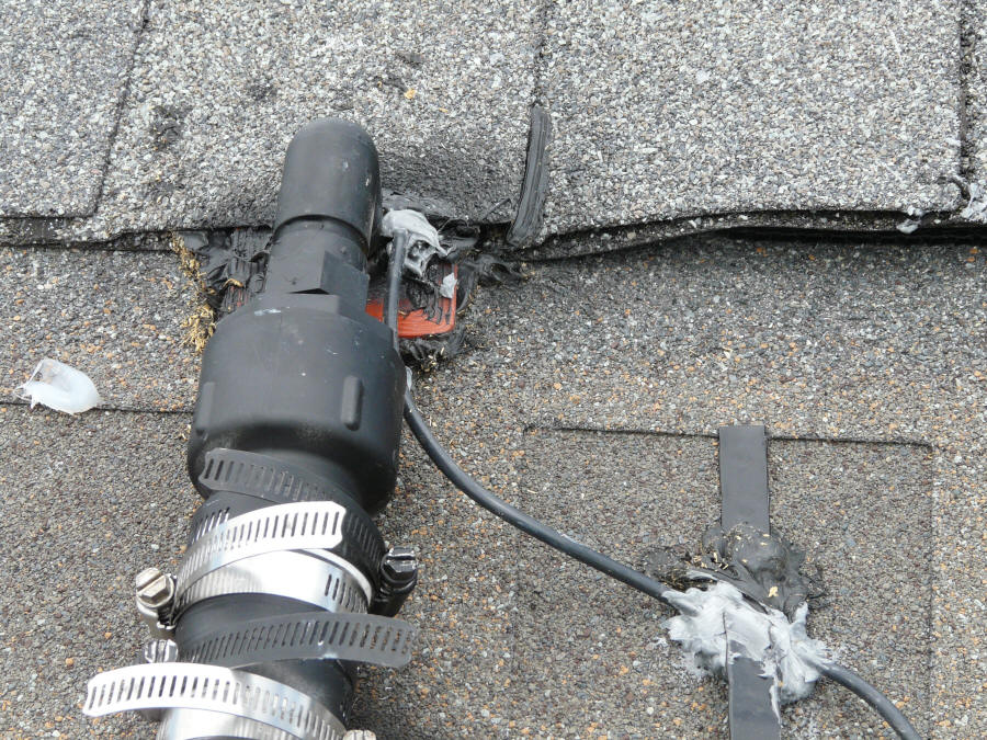
The small roof jack used to route the
supply and return lines for the collector
through the roof.
The return line roof penetration.
The wire is for the collector temperature sensor -- run
through the same roof jack.
(I've got a bit of cleanup work to do here)
I used the long collectors that
run horizontally because the roof would not
accommodate the 10 ft long collectors that are normally used vertically (with
manifolds along top and bottom). I think that the vertical arrangement
would be a better way to go as the collectors could be "hung" from the top
manifold, and they would probably drain back with a little more safety margin,
but the horizontal ones appear to be working OK.
I'm using 3/4 inch CPVC plumbing for the system, so the 1.5 inch barbed
collector manifolds have to be adapted to the 3/4 inch pipe and then the 3/4
inch pipe has to be gotten through the roof. I used some barbed to
threaded PVC adaptor from Lowes -- there may be a better way to do this.
Getting the supply and return lines through the roof is a bit harder than for
regular collectors as the collectors lie flat on the roof -- I used a small, low
profile silicone rubber
roof jack to do this. The transition from the 1.5 inch collector
manifold to the 3/4 inch CPVC seems a bit kludgy to me -- any ideas on a better
way to do this? comments...
The collectors went up fairly easily. I installed them with a bit over
2 inches of down slope toward the supply pipe corner for drain back. I
think that they are actually less visually intrusive than conventional
collectors because they are so flat on the roof.
After doing this installation with horizontally oriented long collectors, I'm
inclined to think that the vertically oriented shorter collectors are a better
way to go. I believe that vertical collectors will be better supported when
they can hang from the top manifold, and that they will drain back better.
There was a strong wind from the south the day after I installed the
collectors. Wind gusts will pickup the lower edge of the collector an inch
or so, and then it drops back down. Not encouraging. I have a
high wind kit ordered, and will see how that works out. As a temporary
measure, I applied a couple dabs of silicone caulk between the bottom of
collector and the roof shingles near the center of the spans between the tie
down straps on each collector.
I don't like the way the horizontally mounted collector is supported by just
three narrow points along its edge by the straps. Maybe I missed something
in the mounting procedure? Maybe there is a better way? Maybe its OK
this way? Comments...
I did have some trouble with small leakage at the ends of the manifolds.
The barbed fittings on the ends of these particular pool heating collectors were
not very deep and the diameter of the manifolds seems just a bit small for
standard 1.5 inch tubing to mate with. Tentative conclusions are to use a
rubber hose similar to what was provided for the collector to collector coupling
(pic above) -- I tried SPA tubing as it was available, but it proved to be to
stiff and was inclined to leak a little. Rubber hose from an auto supply
place worked better. It might also be worthwhile to
find better clamps than the standard hardware store variety shown above. I
ended up smearing a bit of silicone caulk over the end of the manifold before
pushing the rubber tube on and then using as much torque as I thought prudent --
none of these joints have leaked. The company does offer caps to seal off
the unused ends of the manifolds that did not come with my kit -- I have them on
order. Ideas on this? Comments...
Drain Back
I was concerned that the small passages on the pool collectors and the long
(20ft) run would result in poor drain back, but I've done a number of drain back
tests, and they appear to drain back well and with good flow rates. I have the prototype
setup so that I can divert the drain back to a bucket, and once the pump shuts
off, there is a steady stream into the bucket with the full drain back only
taking a bit over a minute.
If after the drain back is complete, if I run a little compressed air into the
return line, I do get some additional drain back flow, so the "natural" drain
back is not getting 100% of the water in the system, but the amount is likely
small enough that it won't cause problems.
Performance General
The performance of the pool collectors is quite good for warm sunny days --
typically better than glazed collectors. But, as the ambient air gets
colder and the water gets hotter the losses that go with no glazing lower the
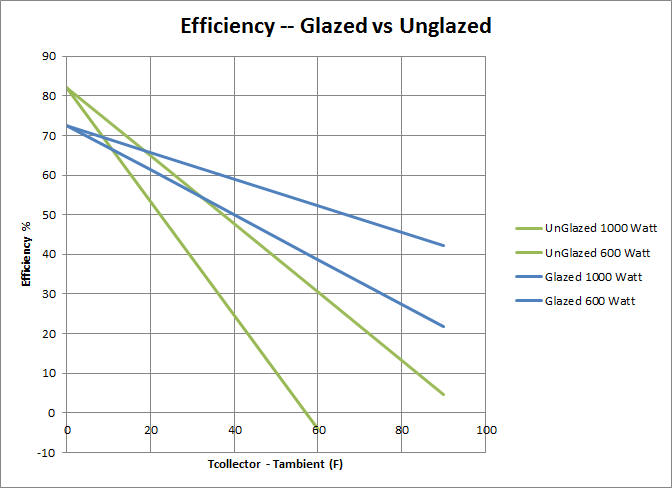
efficiency rapidly. These efficiency curves show the effect.
The plot shows the efficiency of typical glazed and unglazed collectors with
full sun (1000 watts/sm) and part sun (600 watts/sm) ploted against the
temperature difference between the collector absorber and the ambient air. For
example in full sun, an unglazed collector operating with an absorber
temperature of 110F and an ambient midday temperature of 70F, would have a
temperature difference of 40F, which gives an efficiency of 48%. This
might be typical of summer and part of spring and fall.
As expected pool heating collectors are good for warm days and moderate
hot water temperatures -- they actually beat glazed collectors in this area
because they don't have the glazing transmission losses. But, as ambient
temperature goes down, their efficiency falls off rapidly, and performance in cold
weather is poor. To a degree, this can be made up for by increasing
collector size as the collectors are cheap, but when the absorber to
ambient temperature difference gets above 70 or 80F, you are not going to be
making much hot water with an unglazed pool collector. Luckily in most places the
high temperature differences don't exist for much of the year.
One option I want to try next winter is to glaze the collectors with glazing
that allows a limited amount of airflow between the glazing and the collector.
The idea is to limit the convection losses, but at the same time the air leakage
keeps the stagnation temperatures from destroying the collector. Don't
know if this will work or not, but there is one commercial pool heating
collector that uses this design...
There is also an collector made by Aquatherm that claims better cold weather
performance that I need to look at.
Another idea of Nick Pine's is to use greenhouse polyethylene, which (unlike
most glazing) is transparent to far IR heat radiation from the absorber.
So, the absorber would be able to radiate heat during stagnation events more
readily -- albeit with some loss in efficiency.
Lest you think using pool heating collectors is a totally nutty idea,
Fafco offers a solar water heating system based on their pool heating
collectors. Consumer Reports rated it the best of the ones they tested
based on its good economic return. Unfortunately, Fafco does not sell it
for DIY installation and does make a whole lot of data about it available.
They do offer some rough estimates of performance in different climates.
I've not been able to do a full sunny day performance test on the system, but on a
mixed sun and clouds day, from 10 am to 4:30 pm, the system heated the 175
gallons of water from 91F up to 122F -- 48,000 BTU added. Given the somewhat cloudy weather,
I'd call this encouraging.
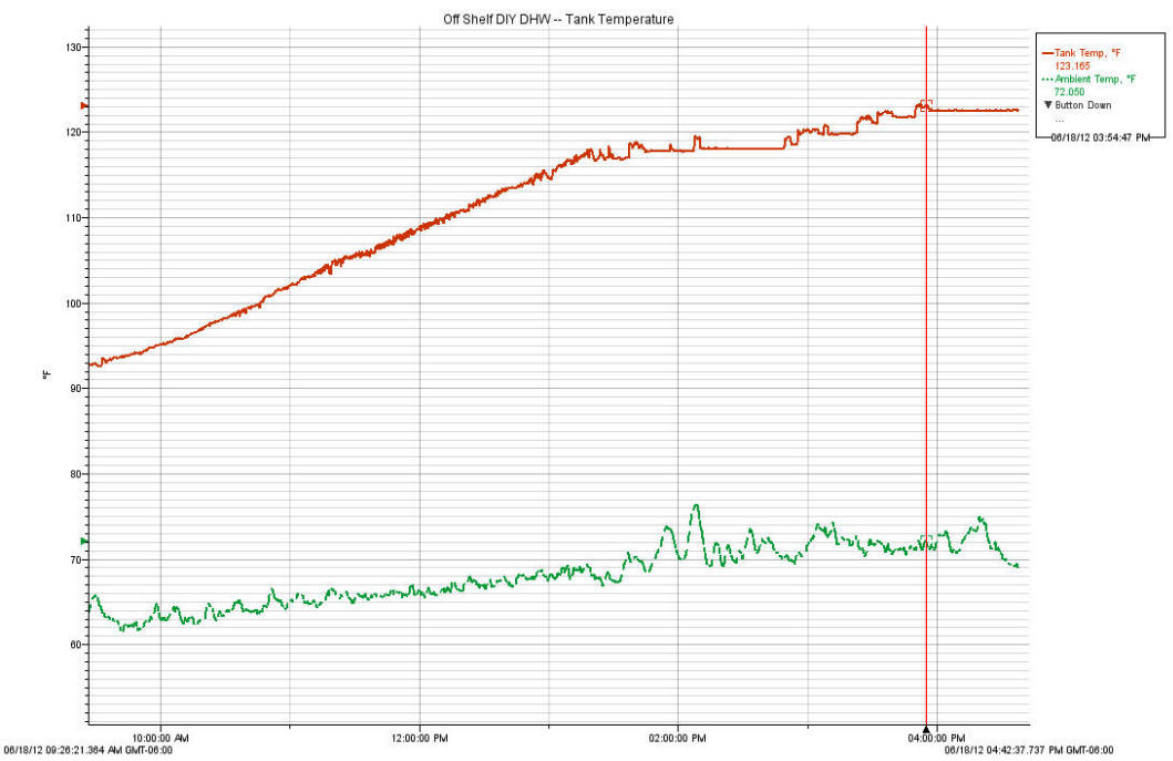
June 18 -- Sunny until 1:30pm when large thunder storm and clouds moved in:
Tank Temperature:
Click on plot for full size.
This is a plot of tank temperature (red) and ambient temperature (green).
The morning was sunny and the tank goes from 93F at 9:30am steadily up to 118
F at 1:20pm. At this point a BIG thunderstorm rolled in -- this was
followed by some sun (but mostly clouds) later. The final tank temperature
was 123F.
Ambient started around 63F and worked up to about 72F.
For the most part the morning winds were light, but stronger in the
afternoon.
Supply and Return Tempratures:
Click on plot for full size
This is a plot of the supply line temperature (blue) and return line
temperature (red).
With a flow rate of about 3.5 gpm, the collector is giving a temperature rise
of about 4.7F, the heat out is (3.5 gal/min)(8.33 lb/gal)(4.7F)(1 BTU/lb-F) =
137 BTU/min or 8221 BTU/hr.
The dips in the afternoon indicate when the thunderstorm came in and cloudy
periods after that.
I'd consider these rough numbers as the flow is just a flow gauge reading,
not a measured container reading, and I did not put the supply and return
thermistors together at the start of the test (as I usually do) to make sure
they are reading the same temperature, or get a correction.
Tank
The tank for the system is the Softank kit from American Solartechnics.
Tom Gocze, who runs the company, has a long history in the solar industry, and
has been making tanks for many years. He also shares a strong desire to
see the price of solar water heating systems come down dramatically.
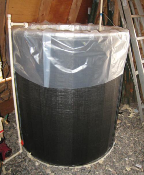
The tank is a unique design. It uses a woven fabric cylindrical outer
layer that takes the pressure loads, 4 layers of 1 inch polyioscyanurate
insulation for about R26 go inside the outer layer. The inner liner
provides the water containment. Cost is $219 plus about $150 worth of
insulation board that you buy locally.
Tank without before lid and finishing touches.
Pro:
On a dollars per gallon basis, the tank is very inexpensive -- about
1/10th what commercial metal tanks cost
The tank ships in a small and lightweight package
Con:
The life may be less than a top of the line stainless solar storage tank
(or not?).
There must be other cons, but I'm hard pressed to think of any? Its
not shiny?
The tank may not be as cool to look at as a $3000 stainless steel solar tank,
but it appears to be a good practical design that provides a lot of storage
volume for a low price.
The tank is an interesting study in load paths and efficient material use. The outer
cylindrical sleeve is
strong in hoop tension and the water pressure (which is substantial) loads it in
tension, so that works nicely. But, if you filled the sleeve with water,
and pushed downward on an edge, the tank would easily be collapsed. Its
the insulation board that is compressed between the inner liner and outer sleeve
that stiffens the tank vertically. Its surprisingly stable -- I can sit on
the edge without collapsing it. Its hard to imagine a tank that would be
more efficient in material use or load paths.
Filled up to the level I plan to use (which allows an air space above the
waterline for venting), the tank holds 175 gallons. By the usual solar
water heating system sizing ground rules this is a more than what would normally
be used for 80 sf of collector, but if you follow our $1K system recommendation
to somewhat oversize the collector and use the collector at a steeper tilt for
better winter performance, the tank size is just about right.
I believe that the Softank design may have changed a bit since I bought mine,
so you might want to check with Tom for the latest.
I'd like to thank Tom for a lot of good ideas for this project.
The tank comes with a good assembly manual, but here is a quick overview of
how it goes together.
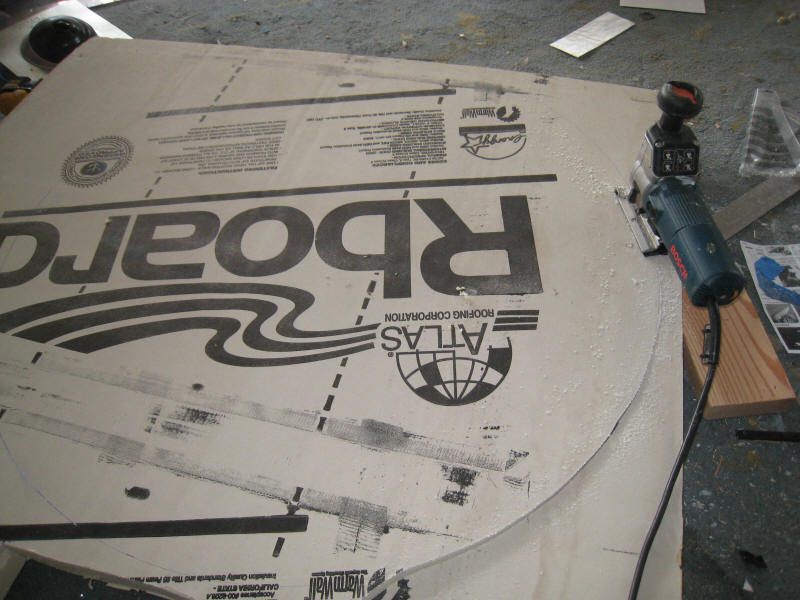
Bottom and Lid:
The bottom and lid are circles of different sizes cut from 2 inch rigid
polyiso insulation board.
Cutting the bottom out with an electric jig saw.
A keyhole type handsaw would also work fine.
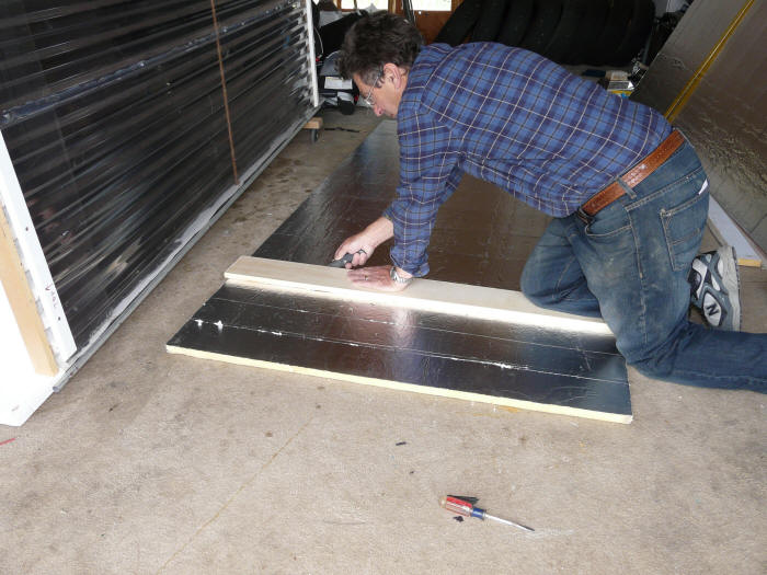
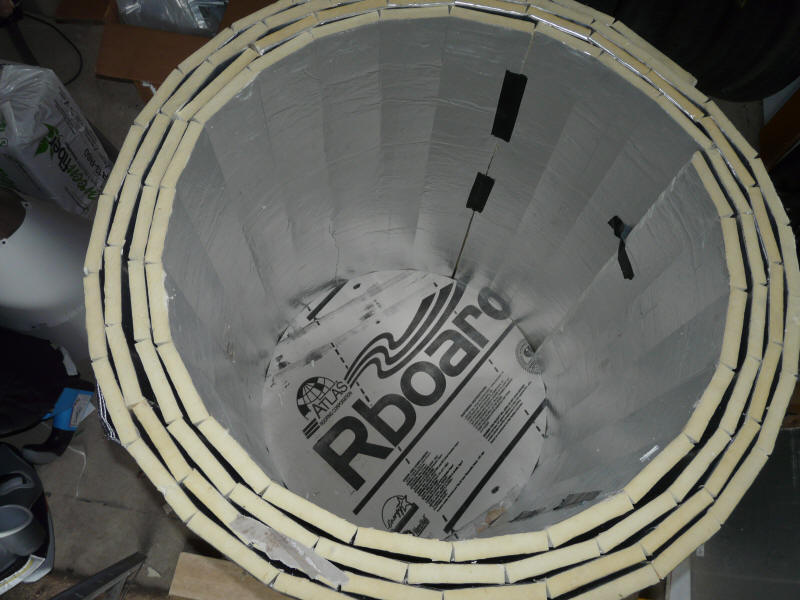
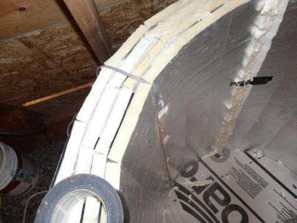
Cutting insulation for sides:
The insulation board for the tank sides must be scored and snapped so that it
can be bent to the radius of the tank sleeve.
Scoring the insulation board at about
six inch intervals.
Snapping the insulation board over a 2 by 4. I later
found that just snapping it over a knee sheetrock style
was faster and worked fine.
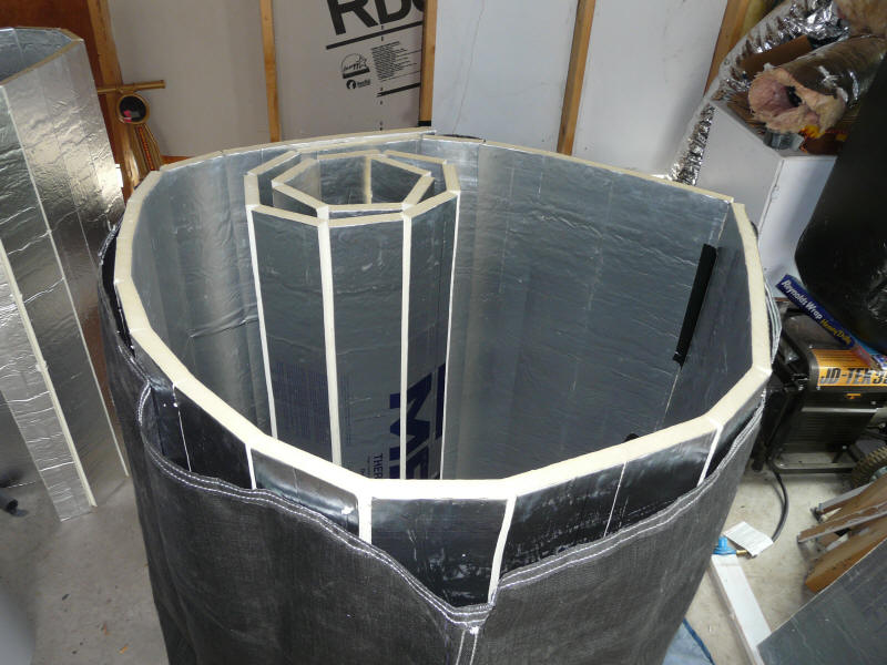
Placing first insulation board in sleeve
Adding 2nd insulation board -- work things around
in a circle keeping as tight to the sleeve as possible.
All 4 layers of insulation board in place and
pushed out against the sleeve.
Placing Lining:
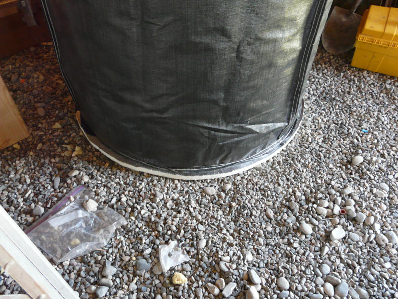
The tank holds about 1500 lbs of water, so it needs a good flat base. I
leveled out the gravel floor, and then cut a rigid foam board insulation base
for the tank to sit on.
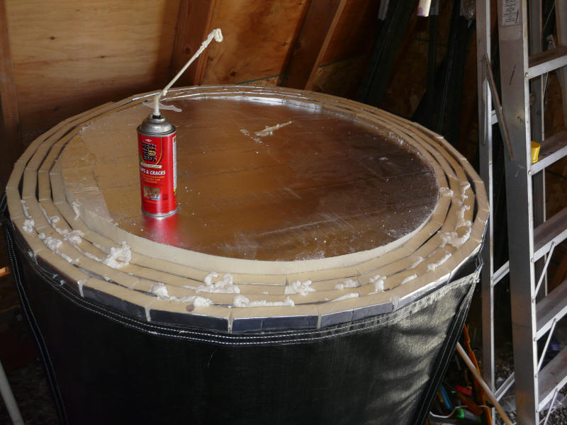
Before installing the lining, I put the lid circle in place to push the side
insulation out against the sleeve, and then filled the cracks and gaps with
Great Stuff. This is probably not necessary, but easy to do.
Leveled out the gravel floor, and added a
piece of rigid foam board under the tank.
After filling gaps with foam, I trimmed them flush
with a sharp knife.
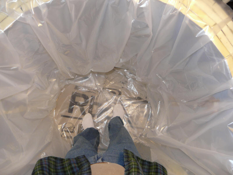
Starting to work the lining into the tank.
Getting in with shoes off to work lining up
against the insulation without any
bridging.
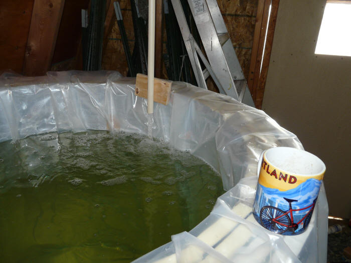
Filling the tank slowly while watching for
any signs of unsupported lining.
You will hear some snap crackle pop as the tank fills and the water pressure
pushes the insulation out. The tank get progressively stiffer as the
water pressure increases.
Putting the tank together is not difficult -- I'd not hesitate to recommend
to someone with no DIY experience.
I used water from our rain water collection system to fill the tank because
it has low mineral content. While I don't think that scaling would
be a problem on these systems unless you have very hard water, it was easy to
eliminate the possibility by using rain water.
Plumbing and Pump
I'm using CPVC pipe for this project. For those not familiar with CPVC,
its a type of rigid plastic pipe that is approved for domestic hot water
plumbing. It uses glued fittings, and the pipe is easily cut with a
scissors like device. Using CPVC is in keeping with
trying to keep it a simple DIY project -- the CPVC goes together easily and does
not require special tools or special skills. Its also easy to fix goofs. PEX or copper would also work
fine.
I've used 3/4 inch throughout the collector circuit. For systems with
longer runs or more collector area, 1 inch may be needed. The
pump sizing procedure will tell you...
Since this is a drain back system, the plumbing has to slope continuously
down toward the tank.
The pump I'm using is a Grundfos 15-58 3 speed cast iron pump. I have
used this pump on several projects and I like it. Its good for
temperatures up to 230F, the three speeds offer some flexibility on static head
and flow rate, its built like a tank, and the price is reasonable ($85).
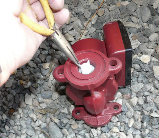
The pump comes with a check valve built into it, which must be removed for
drain back systems --pic below.
Removing the built in check valve -- this is a MUST.
The pump came with 1 inch threaded flanges. I used standard CPVC
fittings to adapt from the 3/4 CPVC supply line to the 1inch flanges.
This shows the plumbing laid out on the floor before being put in place.
The pump mounted into the 3/4 CPVC supply line. The line to the right is
the U-tube that
goes up over the tank wall and then down to the bottom of the tank. The
U-tube allows
the pump to maintain its prime without having any low penetrations of the tank
wall.
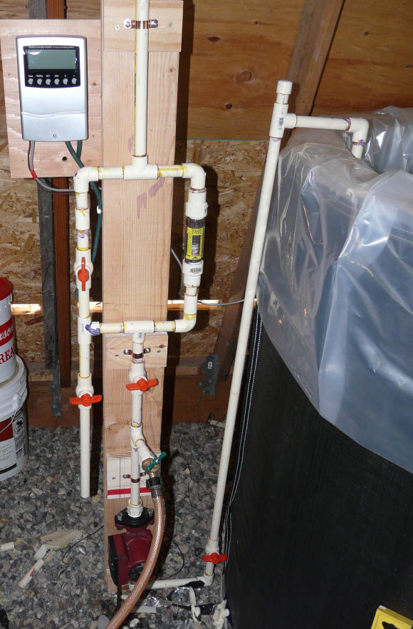
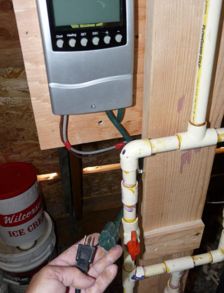
The picture above shows the plumbing setup around the pump that I'm using for the prototype. There is
more here that would normally be used in a regular system.
- Pump is on the bottom with the u-tube going from the
bottom of pump up and over the tank wall -- it goes down inside the tank to
about 3 inches from the bottom of tank.
- The red handled valve at the bottom of the u-tube
allows the pump to be removed without syphoning water out of the tank.
- The red handled valve above the pump in conjunction
with the hose faucet (green handle) allows the pump to be primed by hooking a
garden hose up to the faucet and running water INTO the faucet to flood the pump
and u-tube with water. The pump won't self prime, so some means must be
provide to prime it.
The faucet valve can also be used to add water to the tank.
You need a double female hose fitting to adapt the male end of the garden hose
to the male faucet -- hardware stores sell these.
- The lower vertical tube and valve to the left were
added for testing so that I can divert the drain back water into a bucket to see
how well its draining and measure the volume. Not needed on a "production"
system.
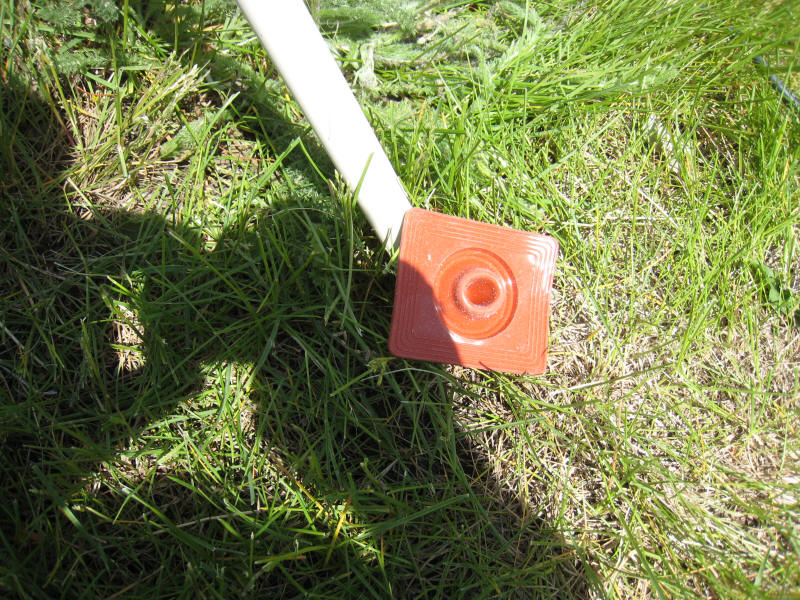
- The yellow gadget is a flow meter that can be used to
measure flow rate. It is positioned so that the middle of the flow valve
is at the target water line for the tank, so it can also be used to check the
water level in the tank. The jury is still out on whether this is a good
way to go.
The valve to the left of the flow valve allows the flow valve to be bypassed in
order to evaluate how much the flow meter resistance effects drain back.
For most drain back systems, the plumbing above the red handled valve would
just be a single straight run upward.
Pump power on high speed measured by a Kill-A-Watt is 76 watts.
The flow rate is about 3.5 gpm. This works out to about 0.044 gpm/sf,
which is fine.
The pump should be placed as far below the tank waterline as possible to
increase the static head at the pump inlet -- these pumps will not work if the
head at the inlet gets to low.
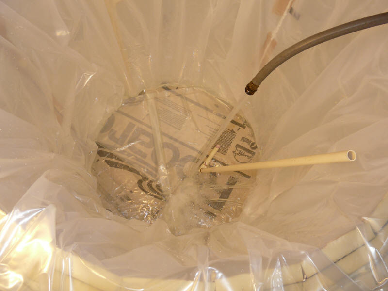
This is the return line coming back to the tank from the collectors without
the lid on the tank.
The return line MUST be terminated above the tank water line so that air can
flow up the return line during drain back.
The green cast of the water is probably algae. I filled the tank from
our rain water collection system to get water with low mineral content, and it
has a little algae growing in it. My experience is that as soon as the
water in the tank gets heated up to a high temperature, the green will
disappear.
Any thoughts or ideas on the pump and plumbing? Go to
comments....
Controls
The controller is a standard differential controller from
www.sun-pump.com model SR208C. It
provides all the bells and whistles and costs about $90. I have been using
one on my other system for more than a year and it has been doing fine.
The controller reads thermal sensors on the collector and in the tank.
When the collector temperature exceeds the tank temperature by a margin that you
set, the controller turns the pump on. The pump runs as long as the
collector temperature stays above the tank temperature by a margin that you set.
The controller has many other extra functions that can be used optionally to
control various odds and ends.
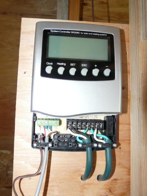
Picture above shows the differential control wiring. The right green
wire plugs into a wall outlet. The left green wire goes to the pump.
The left brown wire goes to the collector temperature sensor. The left
grey wire goes to the tank temperature sensor. All of the wiring is easy
DIY -- just push the wire in and tighten the screw terminal.
In the picture above, the pump power output from the controller is wired to a
female plug, and the pump is connected to the male plug. This is an easy
way to allow the pump to be run independently of the controller for testing or the like.
This can be made by just cutting an extension cord in half.
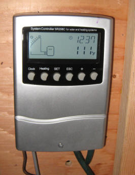
Normal display on controller
Thermal Sensors:
The tank thermal sensor and wire are pushed into one of the vertical
insulation board joints and then siliconed over making sure that no sharp edges
that could cut the lining are exposed. You want the sensor close enough to
the lining to have good thermal contact, but not exposing anything that might
cut the lining.
Picture shows the sensor wire entering the tank and going down the vertical
insulation board joint. The sensor is installed at the same level as the
pump
intake pipe -- about 3 inches from the bottom of tank.
The collector thermal sensor is currently installed on the top surface of the
collector embedded in silicone caulk. The jury is still out on whether
this is a good placement and mounting technique -- any ideas?
comments....
Heat Exchanger
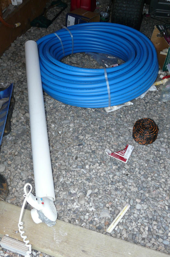
The heat exchanger is not installed yet.
The heat exchanger is a 300 foot coil of 1 inch diameter PEX.
The incoming cold water makes a single pass through this heat exchanger coil on
its way to your regular hot water tank. This is the same system that I use
in the $1K system. The pluses and
minuses are explained on this
page...
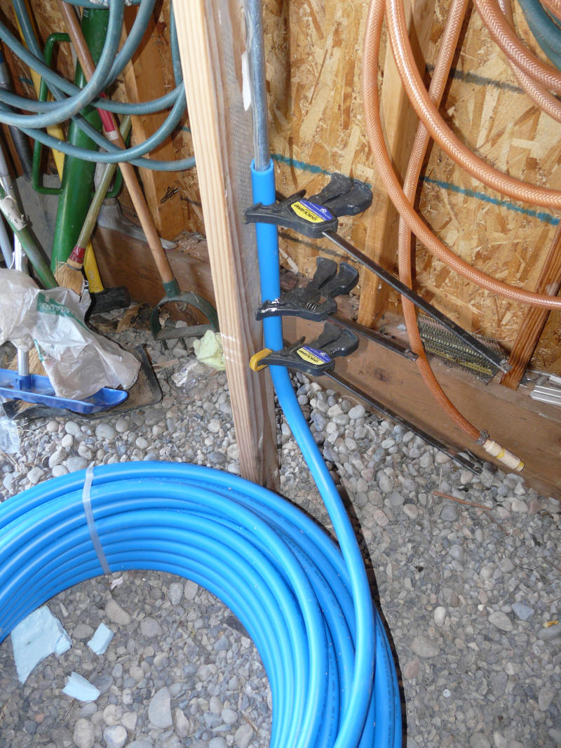
I'm still mulling over how to hang the heat exchanger in the tank.
Leaning toward putting the coil in near the top of the tank and flat as in the
$1K system. The ends of the PEX would be bent up 90 degrees and exit the
tank vertically at the tank sidewall. Pictures below is an attempt
at forming the bend -- works pretty well, but the PEX tends to want to go back
to its original shape.
While the bend is a bit awkward, I would like to avoid the use of any
fittings inside the tank.
Heating the first few feet of the PEX coil
with a pipe and hair dryer prior
to bending.
The heated PEX bent upward 90 degrees
to exit the tank.
The plan is to support the coil in the tank with polypropylene rope.
When the coil is full of water, its has very little weight (nearly floats), but
I would like the supports to be able to support the coil even if the tank water
is drained, and I would rather not have it hanging on the PEX pipe inlet and
outlet.
Once the coil is in the tank, I plan cut the bands holding it in a coil, and
separate the PEX coils using short T shaped pieces of half in CPVC -- this will
improve the heat transfer from solar tank water to the PEX coil water.
Any ideas on best way to get the coil end out of the tank and/or how to
support the coil? Or, anything regarding this or alternate heat exchanger
designs? comments....
Cost
Here is a rough cost breakdown:
Collectors -- 80 sf with mounting hardware
$160 (incl shipping)
The system qualifies for the 30% federal tax credit, and may qualify for
state or other rebates. For example in MT (where I am) it would qualify
for the $500 renewable energy tax credit. The reason that this system
qualifies for the federal tax credit and the regular $1K system does not is that
the collectors are SRCC certified under the OG100 program.
For me, if I did not already have a solar water heating system, this system
would be essentially free with the $500 tax credit from MT (one for me and one
for my wife), and the federal tax credit.
Comments
I am very interested in hearing any thoughts or suggestions you might have
during this time when its still easy to change the design.