
Search
The Renewable Energy site for Do-It-Yourselfers
Serpentine Solar
Collector Drain Back Testing
|
This is a quick test to see
how well a solar collector that uses a serpentine plumbing arrangement
will drain in a drain-back style system.
Serpentine collectors use a
piping arrangement that looks like this:
 The
collector uses a single pipe that winds its way down from the top to the
bottom. So, there are a bunch of near horizontal runs with bends
connecting the horizontal runs. A nice feature of the serpentine
collector is that only a single run of pipe collects heat for the whole
collector -- there are no top and bottom manifolds with many vertical
risers connecting them. The
collector uses a single pipe that winds its way down from the top to the
bottom. So, there are a bunch of near horizontal runs with bends
connecting the horizontal runs. A nice feature of the serpentine
collector is that only a single run of pipe collects heat for the whole
collector -- there are no top and bottom manifolds with many vertical
risers connecting them.
|
|
I would like to use this arrangement
on the PEX collector I'm working on, and would also like to use a drain back
system. So, the question is, will a serpentine collector reliably
drain back to the storage tank when the pump stops?
I've been running a prototype
PEX serpentine collector for a
couple months, and it has always drained back quickly and reliably, but I
thought it would be worthwhile to look into this further with a test on a
serpentine piping arrangement that uses clear tubing so that you can see the
actual drain back process. It turns out to be an interesting process
(at least to me).
The Setup

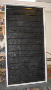
The picture shows the test setup.
The bucket has a small submersible pump that pumps water into the lower end of
the serpentine arrangement of clear plastic tubing. The water returns to
the collector via the pipe coming down from the upper left corner of the
collector. The blocks of plywood just guide the clear poly tubing into the
desired shape.
When the collector backing board is
level, each run of the collector has a slight down slope (about half an inch of
the length of each horizontal run).
To do each test, the pump is turned
on until flow is well established. Then the pump is turned off to allow
the drain back process to be observed.
Note that for drain back to occur,
water must be pumped into the bottom of the serpentine run, and the return pipe
must be kept above the water level in the bucket (this is true for any drainback
system).
The tubing is mostly half inch ID,
but the last section (slightly more white in color) is 3/8 inch ID.
There are two tubing splices that introduce some flow resistance.
The initial test was done with clear
tap water. After that, a tiny bit of dish washing detergent was introduced
to see the effect of reduced surface tension. Some ink was also added to
be able to see the fluid more easily.
Tests were done with front to back
tilts ranging from 70 degrees (nearly vertical) down to about 20 degrees.
In addition, in some tests the panel was tilted to the left or right to see what
happens if the panels is not installed level.
A Typical Drain Back
After flow is well established, and
the pump is turned off to start the drain back, here is what happens:
A bubble or air front begins at
the bottom of the return pipe (this is why it must end above the water
level).
This air front advances up the
return pipe until it gets to the top of the collector.
The air front then advances down
the collector at a fairly good pace -- about 1 ft per second for this
collector.
Nearly all of the water in the tube drains during this phase, which lasts
about 15 seconds on the test collector.
There is a little water left in
the tubing after the air front passes, and this water drains in a small
trickle along the bottom of the tube as long as the tube has a down slope.
This 2nd phase of the drain
process takes longer -- typically about a minute.
This is a picture of the air front
advancing along the tube:
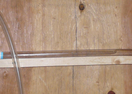
The air front is near the right edge
of this picture. Water to the right, air to the left.
This air front advances from the top
of the collector to the bottom quite quickly and cleanly. It is even able
to advance without any trouble when the collector is tilted so that it has to
advance slightly uphill.
Most of the water drains during this
phase. The water left behind after the air front passes drains in a slow
trickle over time.
Test 1: Steep Tilt -- Level
Collector
In this test, the collector is set up
with a tilt of about 70 degrees (nearly vertical), and the collector backing board is level in the
left to right sense, so that each "horizontal" run of the collector has a slight
down slope.
In this configuration, when the
pump is shut off, the collector drains in about 15 seconds. There is a
very well defined air front that advances up the return tube, and through the
collector. The air front advances in what appears to be a very
reliable and repeatable manner.
The bit of water left in the tube
after the air front passes drains down in a 2nd phase that goes on for a while
(perhaps a minute or so). At the end of this, it appears that all the
water has drained, although there may still be a very thin film on the
pipe walls.
I tried this test initially with
plain water and then with just a couple drops of dish washing detergent in the
water. The idea was to see if the lower surface tension effected drainage.
There did appear to be a little improvement. The detergent
probably made more difference on the later tests, but I did not do these with
plain water, so don't know for sure.
In all this appears to be a pretty
robust drain back that I would feel pretty confident in working over the long
haul.
Test 2: Less Tilt -- Level Collector
This is the same as test 1, except
that the collector tilt is reduced to about 35 degrees.
The results are pretty much the same,
but the drain back time is greater -- about 20 seconds.
The secondary drain process after the
air front passed left some very small pockets of water in the tube --
little beads of water, about 1/8 th inch in size.
So, not surprisingly, steeper tilts
result in slightly faster drain backs, but the drain back process still seemed
very repeatable. I am sure that if you kept
reducing the tilt you would get to a point where the collector would not
reliably drain back.
Note July 18, 2008: did one last
test at a very low tilt of 22 degrees. This worked fine, no increase
in time, and no hesitation even with this low tilt.
Test 3: Steep Tilt -- Slight
Non-Level Collector
This is the same tilt as in test 1
(70 degrees), but the collector back board is not level in the left to right
sense. The backing board was adjusted so half of the straight runs had a
slight uphill tilt.
The first phase of the drain back
appears unchanged from test 1. The air front advances along both the down
hill and uphill runs at what appears to be the same pace as in test 1.
The reliability of this phase of the drain back appeared to be unaffected by the
adverse slope on half of the straight runs.
The 2nd phase of the drain back
results in some pockets of water collecting at the start of each uphill straight
run. None of these got to the point of filling the tube diameter.
Most of the tube length was full drained, with these small pockets of water at
the start of each uphill run.
Test 4: Steep Tilt -- Very Non-Level
Collector
This is the same as test 3, except
that the left to right tilt was increased to about 5/8 inch over the length of
the straight runs.
So, every other tubing run slopes up
by an amount greater than the tube ID.
The first phase of the drain back
appears unchanged from test 1. The air front advances along both the down
hill and uphill runs at what appears to be the same pace as in test 1.
The reliability of this phase of the drain back appeared to be unaffected by the
even more severe adverse slope.
The 2nd phase of the drain back
resulted in pockets of water at the beginning of each of the uphill runs that
got large enough to block the full diameter of the tube. Here is a
picture of one of these.
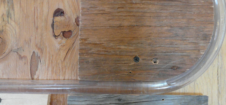
With 5/8 inch of adverse slope, the
2ndary phase of the drain back results in pockets of water that grow to the full
diameter of the tube for a short distance at the start of each uphill leg.
While I see no reason to subject the
collector to this much out of level abuse, I don't think that these little
pockets of water freezing would be likely to cause any damage to a PEX
collector, since there is plenty of expansion room for the freezing process.
It might delay startup slightly on the next morning, since these pockets
would need to melt out to allow flow.
Rough Conclusions
The drain back process in this test
appears to be pretty robust and reliable. This is reinforced by about 3
months operation of the prototype PEX collector without a hint of any drain back
problems.
It appears that it is possible to use
drain back in a serpentine collector as long as:
-
The collector has a significant
tilt angle. The shallower the collector tilt, the more risk that the
collector will not drain reliably.
-
All of the straight runs in the
collector have a slight down slope. While most of the water in the
collector will drain even if some of the straight runs are horizontal or
even have a slight up-slope, its seems prudent to have all legs slope
slightly down.
-
The supply and return plumbing
must all slope down toward the storage tank (as for any drain back system).
-
The pipe that returns fluid from
the collector to the storage tank must terminate in the airspace above the
water to allow the air bubble to advance up the pipe (as for any drain back
system). And, the storage tank (drain back tank) must be vented to
atmosphere.
I suppose that one caveat is that if
you developed significant deposits inside the tube, it might effect drain back
in the long term. To me, this seems unlikely in a well designed system,
and would eventually lead to other kinds of problems (like blocked tubes).
Any thoughts, comments, or
suggestions on this would be appreciated --
Gary ...
Gary
July 15, 2008, September 12, 2008
