Search
The Renewable Energy site for Do-It-Yourselfers
DIY PV System --
Wiring the PV System
Back to the PV
System page...
This page covers all of the wiring of the PV
system and the connection to the house wiring.
| |
Safety Warning and Disclaimer
There are serious safety
issues involved with wiring your own system. The voltages are
high, and potentially lethal. When you couple electric shocks with working
on the roof, there is an obvious potential for serious accidents.
PV systems have the added
hazard that even when the grid power is turned off, the system can be
"live" and present a serious shock hazard -- hundreds of volts on some
systems.
If you don't feel like you
want to put
in the time to learn how to do this correctly, then find an electrician
that you can partner with to do this part.
I want to make it very clear
that I am not an electrician, and I take no responsibility whatever for
the correctness of the wiring hints below -- you need to do your own
homework!
http://www.builditsolar.com/Contact/legal.htm |
Overview of the Wiring
The wiring is pretty simple.
Each PV panel plugs into its
dedicated inverter. These are just push in connections.
Each inverter just plugs into the
next inverter. You can connect up to 15 inverters in a row just
plugging one into the next. These are simple push in connections.
The power from the last inverter goes to a junction box mounted at the
array. The connection going off to the house wiring is made at this
junction box.
The inverter produces 240VAC
house power, so the power at the array junction box is ordinary 240VAC house
power.
The 240VAC from the array
junction box gets routed to the house routed via an underground conduit, and
then through a disconnect switch, and then connects to the house power
via a new circuit breaker in your house circuit breaker panel.
The EMU unit that monitors the
performance of the system, and sends data into the Enphase website just
plugs into a regular power plug in the house, and does all of its
communicating with the inverters over the power lines. It does not
require any wiring at all.
Here is a very simple diagram of the
micro-inverter system
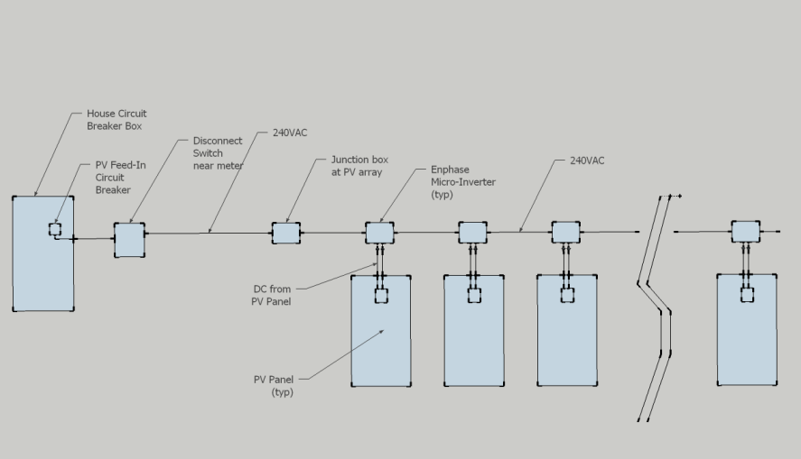
The Enphase wiring diagram is here...
I did the wiring in this order:
1- The junction box at the PV
array, wiring from PV array to the disconnect switch on the house, the
disconnect switch, the wiring from the disconnect switch to the circuit
breaker panel.
2- The connection of the new PV
feed in circuit breaker in the circuit breaker box, leave the breaker off
once it hooked up.
3- Hooking up the PV panels to
the micro-inverters, and connecting the micro-inverters to each other, and
to the array junction box.
The thinking here was that the wiring
is "cold" for step 1 (most of the wiring), so you don't have to be working on an
energized system for most of the wiring.
If you do the wiring this way, the
only time you will be working on an energized circuit is when you hook up the
new PV feed-in circuit breaker to the circuit breaker box.
If you are doing a roof mounted
system, you will probably have to connect the PV panels to the
micro-inverters as you go. This should be done with the PV panel covered
so the connection is made with no load. If you leave the cable from the
last micro-inverter to the array junction box unplugged, then you can be sure
that the PV array will not be energizing the rest of the wiring until you are
ready for it.
Grounding Requirements
The system must be properly grounded
-- all of the components listed just below must be electrically bonded together, and connected
to ground.
The PV panel frames
The PV panel support rails
(including ground bonding across splices in the rail)
The micro-inverter case grounds
The PV array junction box (if
metal)
The Disconnect switch housing (if
metal)
All of the components must be
electrically bonded together with a code approved method. For example, the
PV modules are bolted to the aluminum support rails, but this is no an approved
grounding connection. The modules must either be connected to the rails
with a separate grounding conductor or with the Weeb washers that we used.
The inspector is likely to look at your grounding scheme carefully, and its
important for the safe and reliable operation of the system, so be sure
to do it right.
Some areas may have additional
electrical requirements, so you need to research local rules that may apply.
I used the Weeb washers to ground the
PV panels to the support rails, and to ground the sections of rail to each
other. This is shown in the PV panel
mounting section...
I used a continuous length of bare
copper #8 wire to tie all the micro-inverter case grounds together, and ran one
end of this ground wire into the junction box. In the junction box, the
ground wire is connected to a ground lug as shown in the next section.
The other end of the ground wire
continues on and connects to a ground lug on each PV mount rail, and then
terminates at a new ground rod I installed at the east end of the array.
So, this one length of wire basically grounds the PV panels, rails, inverter
cases and the array junction box by connecting them both to the house ground and
to a new ground rod at the PV array.
I decided to install the extra ground
rod at the array because it seemed like a long path to the house, and we get
electrical storms that can be hard on equipment.
The manual says that the ground camps
on the Enphase micro inverters works with gages 6 through 10, but I tried #10,
and it did not seem to clamp the wire tightly, so I went up to 8 gage to be
sure.
click pictures for full size
|

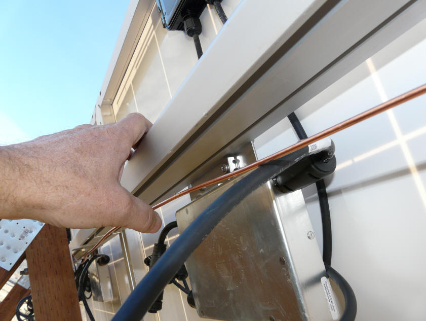
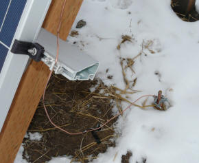
I ran a length of #8 bare copper wire
the length of the array to pick up all
of the micro-inverter case grounds. |
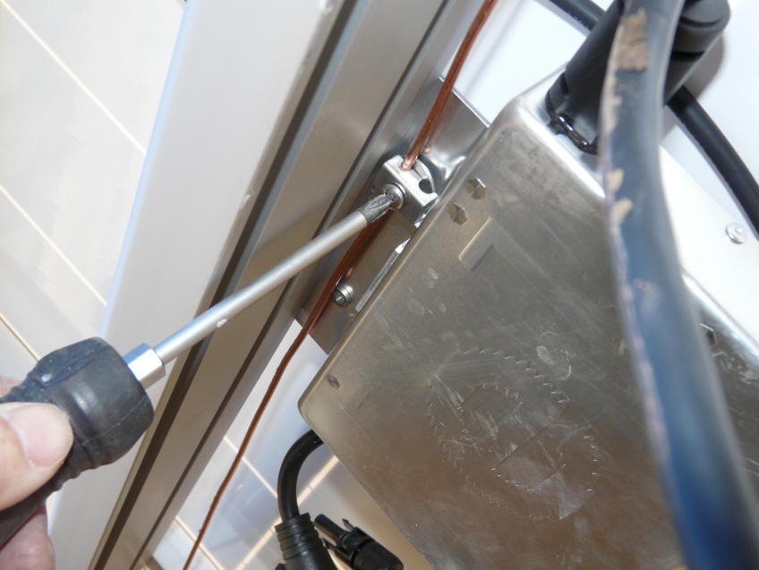
Grounding the micro-inverter cases.
Weeb Washers could also have been used, and
would have been a bit less work. |

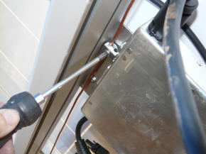
The bare copper wire from the inverter case
grounds comes into the bottom of the
array junction box and into the ground
lug mounted to the left back of the box.
(click on picture for full size)
click pictures for full size
|
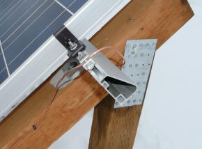
The ground wire from the array Jbox via
the inverter case grounds wraps around
the end, and picks up the ground lugs
on the PV support rails. The ground lug uses
a Weeb washer to make a good connection
to the rail. |
The same ground wire continues through
the lower rail ground lug, and on to
a new ground rod at the array. |
Array to House Wiring
The wiring from the house to the
array should be sized to keep the voltage drop low.
This Application note for the 190watt
inverter provides a table for choosing the gage of the wire from the array to
the house:
http://www.enphaseenergy.com/downloads/EnphaseAppNote_Circuit_Calculations_M190.pdf
In my case with 10 inverters and a 90
ft run, I could have used #12 wire (good for up to 115 ft with 10 inverters),
but I decided to use #10 to allow for adding a few more panels at some future
date.
If you use the direct burial service
entry cable, it can be buried with conduit only for the parts above ground on
the ends. I decided to use conduit all the way, since its not very expensive.
More on the
trench and wring here...
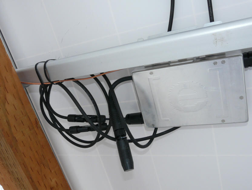
Wiring the PV Array Junction Box
A junction box out at the PV panel
array is used to make the connection from the first micro-inverter to the
wiring that goes to the house. I used a 6 by 6 by 6 metal box for this.
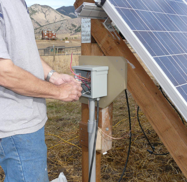
The junction box out at the array. The grey PVC conduit goes to the house.
The black cord
comes from the first in the line of micro-inverters.
The junction box is supported on MDO plywood, which is very water resistant --
its what
freeway signs are made of.
The power coming from the
micro-inverters is ordinary single phase, 240 Volt , 60 cycle AC house power (a
208volt 3 phase option is also available).
I did this wiring before connecting
the micro-inverter cables to the PV panels, and before connecting the new
circuit breaker to the house power, so there was no power applied to this
circuit during the wiring from either the PV end or the house power end.
Enphase sells a kit that includes the
"Enphase AC Interconnect Cable" -- this cable plugs into the first
micro-inverter, and the other end of cable has bare wires to connect to the
wiring from the house inside the junction box. You will need one of these.
The wiring connections in the
junction box are:
- Connect the black (tagged L1)
inverter cord wire to the black wire from the house.
- Connect the red (tagged L2)
inverter cord wire to the red wire from the house.
- Connect the blue neutral
inverter cord wire to the white neutral wire from the house.
- Install a ground lug, and tie
the ground wire from the house and the ground wire from the micro-inverter
cases. The grounding lug should be attached to the box with a self
tapping screw so that it makes good electrical contact with the box.
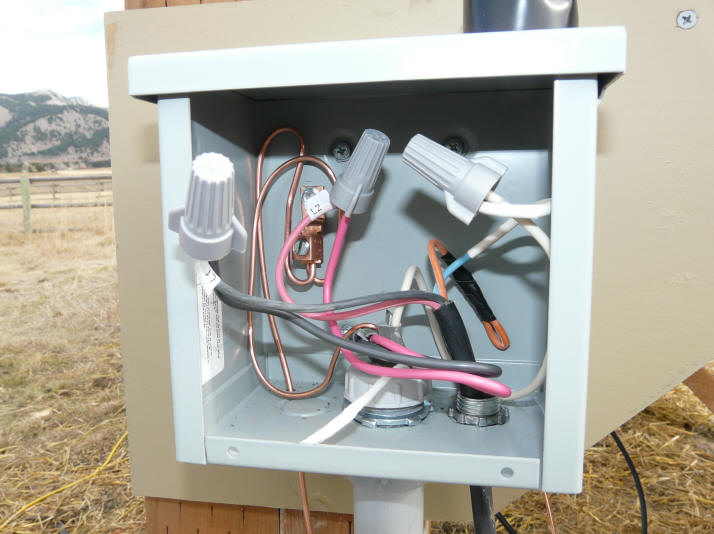
The wiring of the
junction box at the array end.
Make sure the wires enter through appropriate bushings.
The Enphase interconnect cable comes in through a weather proof strain relief
fitting.
The wire to house
exits through the PVC conduit.
The box comes with a metal cover to cover the open side.
Wiring the Disconnect and the
Connection to the House Wiring
In our system, the power from the PV
array goes underground over the the house. It connects to a new disconnect
switch that is right next to the meter and the house power distribution panel.
The disconnect switch is required to
allow utility people to disconnect the PV array to be sure it cannot power the
grid. The disconnect switch should be within 10 ft of the meter, but it
may be possible to negotiate a location that is further away along with a sign
at the meter indicating where it is.
On our house, there is a power
distribution panel with a few breakers right next to the meter box. This
panel distributes power to the main circuit breaker panel, and to a couple other
locations. I was able to add the new circuit breaker to this power
distribution panel rather than having to run all the way to the regular circuit
breaker panel.
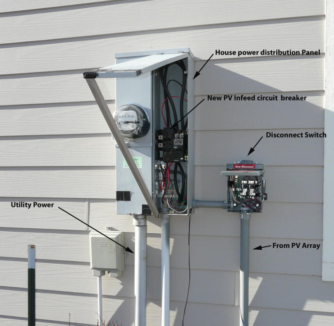
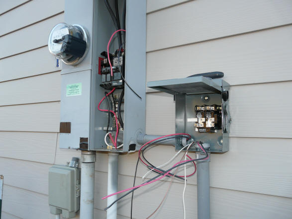
Overview showing
meter, house power distribution panel, and the new PV
array disconnect switch.
The disconnect switch is a standard
item. I got mine with the main order from Whoelsale Solar, but local
electrical supply places will have them. It just needs to switch at least
15 amps at 240VAC, be suitable for outside use, and have a means to lock it in
the off position with a padlock.
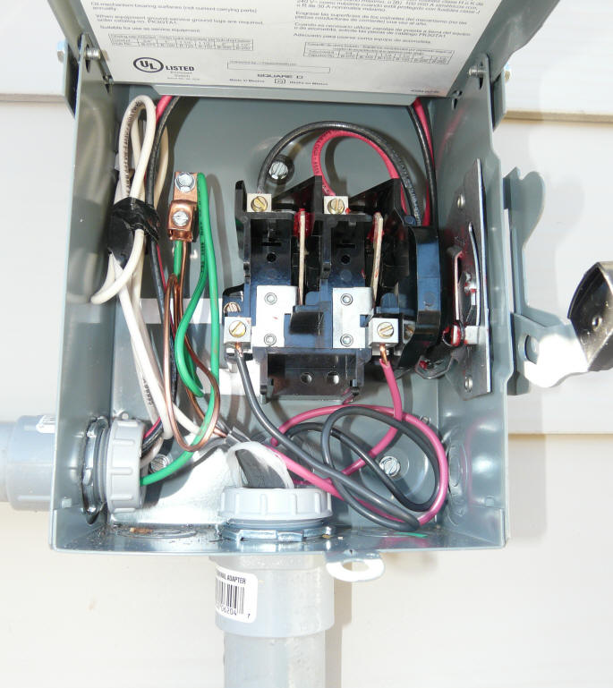
The 240VAC from the PV array comes in
the PVC conduit at the bottom. The wires that connect to the new PC feedin
circuit breaker in the power distribution panel go out the conduit to the left.
I used short lengths of THHN 90C wire
to connect from the top switch lugs to the house power distribution panel.
The wiring connections for the
disconnect switch are:
- Connect the black and red leads
coming from the PV array junction box to the lower switch lugs.
- Connect the new read and black
leads from going to the power distribution panel to the top switch lugs
- Connect the white neutral wires
coming from the PV array Jbox and the power distribution box togehter.
- Install a ground lug, and tie
the ground wire from the house power distribution panel and the PV array
Jbox. The grounding lug should be attached to the box with a self
tapping screw so that it makes good electrical contact with the box.

Finished
disconnect switch.
The placards that indicate that its the Solar Disconnect, and the warning about
both load and line side of switch being powered are required.
The inspector will for sure want to see these.
You buy the
placards separately and stick them on the switch housing.
Making the Connection to the House
Wiring -- the PV Feed-In Breaker
In our case, there was room for a new
circuit breaker in the house power distribution panel that is located right next
to the meter, so this was handy. You may not have a power distribution
panel by the meter, or may not have room in it. In this case, you will
have to install the new PV feed-in breaker in your regular circuit breaker box.
If you did the wiring the way I did,
this is the only time you will be working on "live" wiring, so be careful.
Enphase wants a 15 amp circuit
breaker for the PV feed-in breaker.

The wiring connections for installing
the new PV feed-in circuit breaker are:
- Connect the black and red leads
coming from the disconnect switch to the new circuit breaker terminals.
- Connect the white neutral wires
coming from the disconnect switch to the neutral bus in the distribution
panel.
- Connect the green ground wire
to the ground bus in the distribution panel
Make sure that the disconnect switch
and new PV feed-in breaker are in the off position for now.
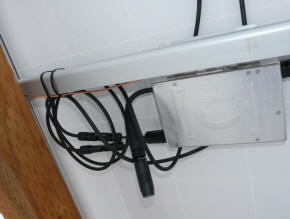
The small current transformers
snapped on the PV feed-in breaker leads, and the small box in the lower left are
the TED "Energy Detective" unit that I'm using to monitor power output -- this
is not really needed, and the the EMU also monitors output, but is a sort of 2nd
check.
So far they have agreed well.

The finished
panel. Note the label on the PV feed-in circuit breaker.
The new permit is
just visible at the top, and this was taken
after the new Net meter was installed.
Wiring the PV Panels and Inverters
I waited until after sunset one
evening, and made all the connections with no sun on the PV modules.
I started with the last PV panel and
inverter and worked toward the first one (the one connected to the array
junction box).
Plug the DC leads from the PV
panel into the two DC input leads coming from the micro-inverter.
These connectors are coded so that you can't get them backward. Note
that the inverter has to have the same type of connector that your PV panel
has -- this will likely be an MC-3 or MC-4.
On the last inverter, screw the
cap they provide onto the cord with the female connector -- this protects it
from the weather.
Plug the cord with the male connector into the cord with the female
connector on the next inverter.
Continue on down the remaining
mico-inverters, plugging in the DC wires from the PV module to the inverter,
and plugging the male cord from the current inverter into the female cord
for the next one.
For the final micro-inverter
(nearest to the array junction box), plug in male cord from the last
inverter to the female cord you wired from the array junction box earlier.
Working slowly and carefully, all of
this takes a grand total of maybe 10 minutes :) -- its just pushing connectors
together.

Connecting the micro-inverter plugs.
If you do the connections during the
day, you want to cover each PV panel before you connect it to its inverter.
The next day, I coiled up the extra
wire at each PV pane/inverter, and tied the small coils to the PV support rails
using two outdoor (UV resistant) wire ties per coil. This seems like a
somewhat Mickey Mouse way to support the extra wire, but I've not seen any
better technique -- do you know of a better way to
secure the extra wire in a better way?...
|

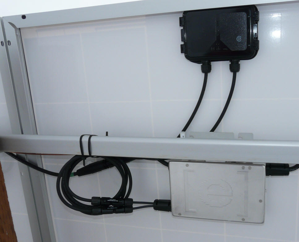
The two connectors to coming from
the lower left of the inverter are the
plug in connections from the PV panel
to the inverter.
The connection from the next inverter down
to the left can be seen behind the other
two connections. |
The last inverter in the line gets this cap
screwed in over its input connector.
The cap comes with the Interconnect kit. |

View of the little coils of wire tied in place.
Kristy (our dog) seems to appreciate the PV panel shelter for bathroom calls.
This completes the wiring (at least
as I did it). You can call the electrical inspector at this point and get
the work signed off.
I left everything off until the
inspector had a look at. We turned it all on when he was there.
Bringing the System up
You might want to do a final check of
all your wiring.
At this point, you can plug in the
Enphase EMU unit, flip on the PV feed circuit breaker, and turn on the PV disconnect
switch. If there is some sun on the panels, they should start reporting in
and show up on the EMU display. The EMU shows the number of connected inverters on the
lower right of its display. It will take a few minutes for all of the
inverters to report in.
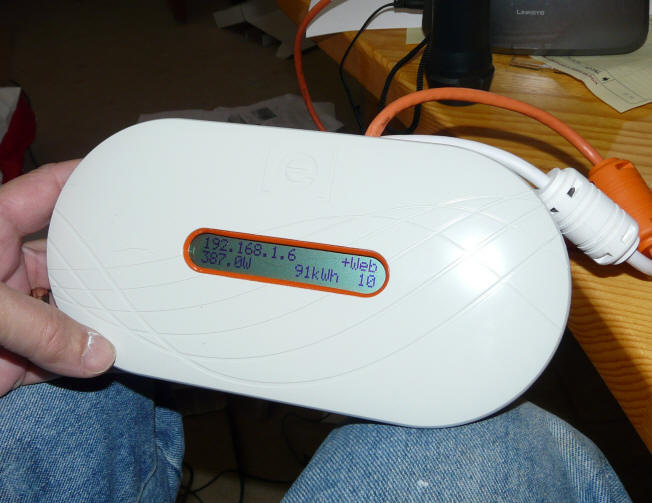
The EMU unit.
Upper left is the
EMU's IP address.
+Web indicates it is connected to the Enphase mother ship.
387W indicates the
array is generating 387 watts (it was cloudy).
91kwh is the
lifetime energy production of the array.
10 indicates that
all 10 micro-inverters are online.
When the EMU first boots up, it will
report on signal strength between the inverters and the EMU. If the EMU is reporting low signal
strength, you may have to move it to a plug that is closer to the circuit
breaker box.
You can use the Ethernet cable that
Enphase provides to connect the Ethernet port on the EMU to the Ethernet port on
your computer. Then using your web browser, enter the IP address that is
displayed in the EMU display. This should connect you to the EMU local
interface. Here you can check on how much power is being produced
and on any error or status messages that the micro-inverters are sending out.
Wiring Pointers
I am by no means a wiring expert, but
here are a few pointers for not so experienced "electricians"
- Buy a good wiring basics
"how-to" book. It probably will not cover PV systems specifically, but
it will cover wiring basics that you will need to know.
If you have not done any wiring
before, this may not be a good project to cut your teeth on -- might be good
to get help from an electrician.
- When a you bring a wire into a
junction box, make sure to leave plenty of extra wire -- about 8 inches of
extra slack. This allows for future reconnections if needed.
Inspectors will look for this.
- Be careful to meet the
grounding requirements. This not only a safety issue, but inspectors
will be sensitive to proper grounding. All metal boxes need to be
grounded. Some inverters are sensitive to where the grounding point
is.
- Make sure your PV feed in
circuit breaker is small enough to protect the wire gage you use out to the
PV array -- e.g. don't use a 40 amp breaker on 10 gage wire that is rated
for 30 amps. Enphase says to use a 15 amp breaker.
- Make sure you install the
proper placards to mark the disconnect switch(s) and the PV feed in circuit
breaker. Inspectors will require these.
- The disconnect switch should be
near the meter. If its more than 10 ft away, then you need to check
with the local inspector on what is allowed in your area-- you may be
allowed to have a clear sign at the meter saying where the disconnect is.
The disconnect needs to be accessible to utility people. It needs to have a way
that a utility person can padlock it in the off position.
If you are using a system with a
large single inverter installed near the meter, and it has a built in,
lockable disconnect, I would still check with the local inspector to make
sure they will accept this.
- Be sure that any junction boxes
you use are have enough volume for the wire you plan to install in them.
You can look this up, or just buy a box that is plenty big.
- If in doubt about a wiring
issue, you can try asking the inspector by phone. The inspectors I
have had have been willing to answer well thought out questions, but this
may depend on the inspector.
- If the wiring seems like more
than you want to tackle, you can always find an
electrician to work with. The actual labor involved in making the
connections is fairly minimal, and it should not cost that much to hire it
done.
Gary November 22, 2009