Construction Details for a PV Array at Craters of the Moon Monument
On a recent vacation trip we stopped a couple national monuments in which
the visitor centers had grid-tied solar electric arrays. I thought
that the arrays showed some nice construction detail, and took quite a few
pictures.
The pictures below show show some of the construction details that I
thought might be helpful to people building PV installations.
The pictures are from Craters of the Moon National Monument. I might add that
Craters of the Moon has a lot more interesting things to look at than PV
arrays, but I figure those things are covered in a lot of other places :)
The drive up from Twin Falls Idaho along US 93 and then Idaho 33 toward
Craters of the Moon was exceptional.
Craters of the Moon has been working on various sustainability projects...
And, in more detail here...
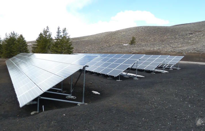
The large 50 KW PV array at Craters of the Moon.
Mounts
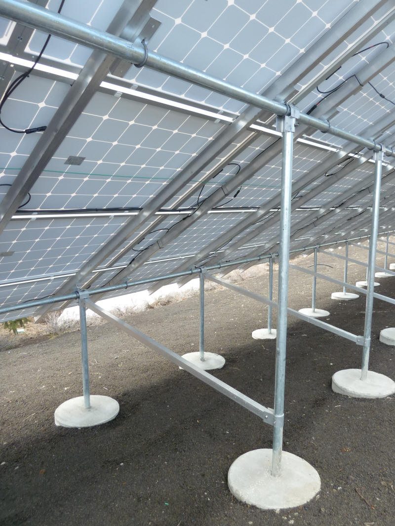
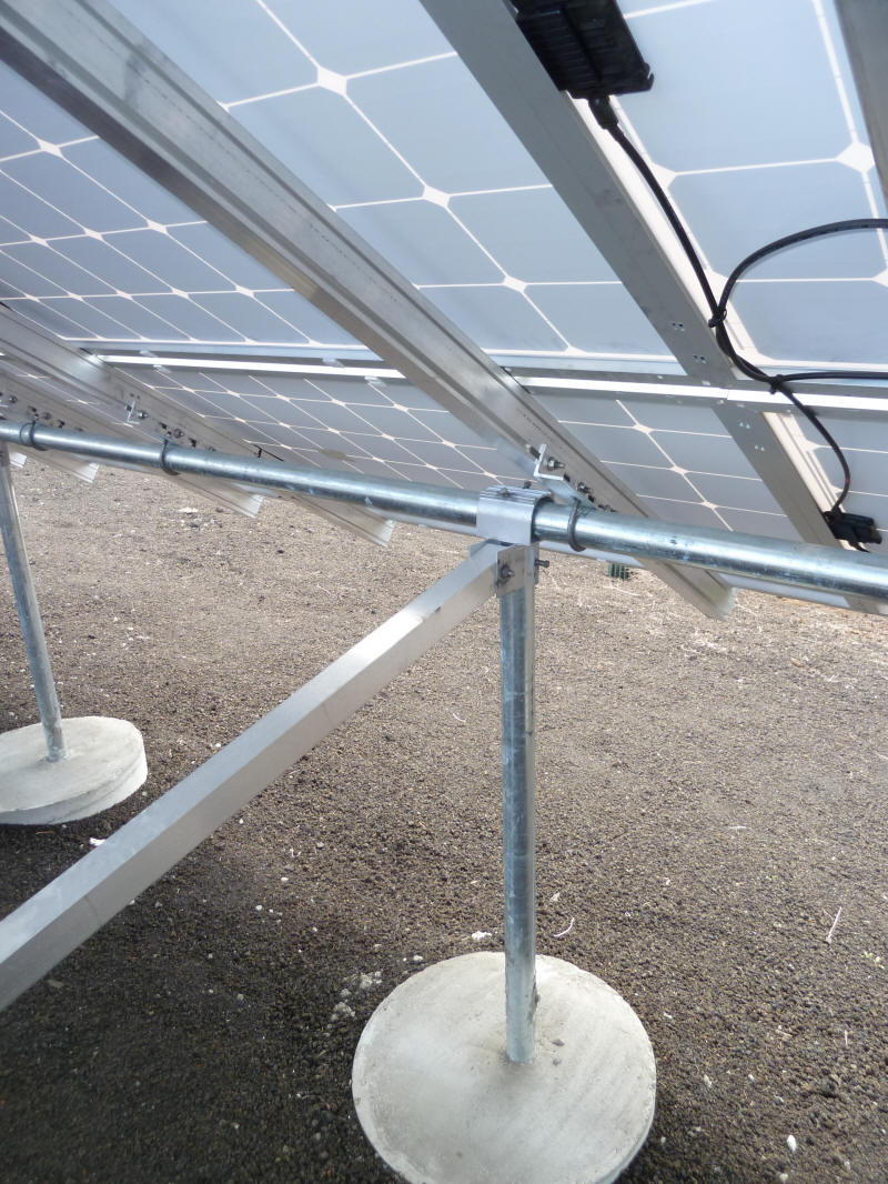
The ground mount system is based on galvanized steel pipe.
The pipe members are attached to each other by standard industrial fittings
that just slide onto the pipes and then are secured with what are basically
large set screws. This is a very clean, open, and simple mounting
system that appears to be very sturdy and looks like it will provide a long
life.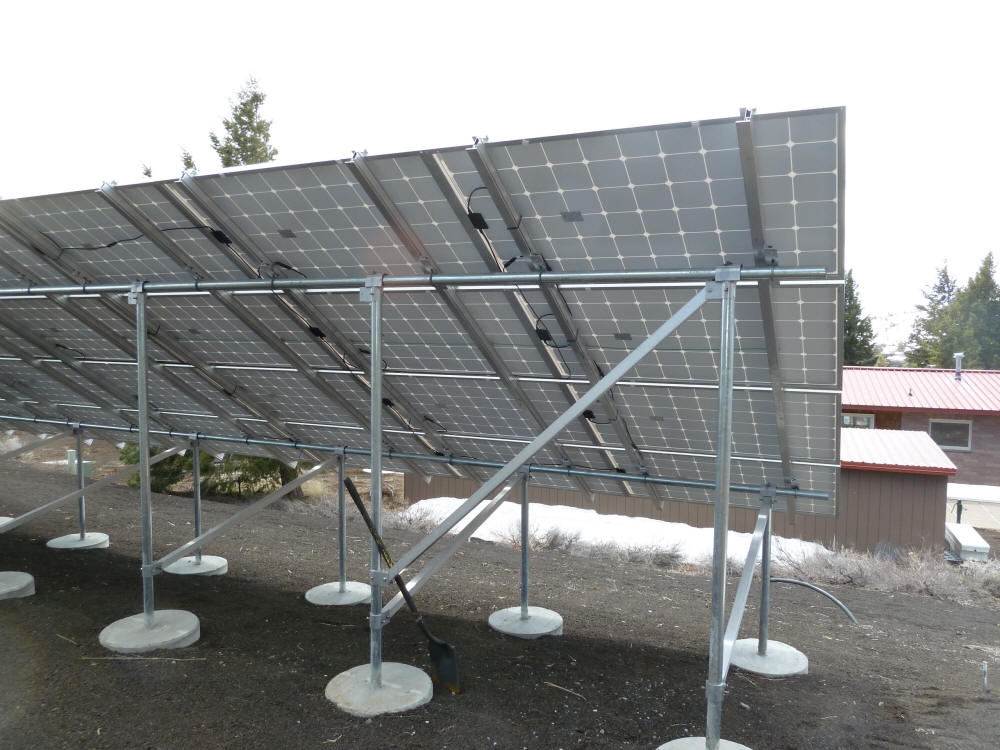
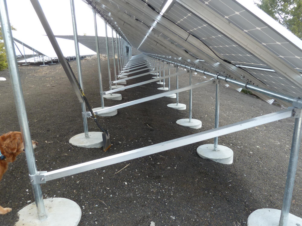
The pipe rack mounting system has a nice open and clean look -- the
shovel is optional.
Here are a bunch of pictures showing details of the mounting system.
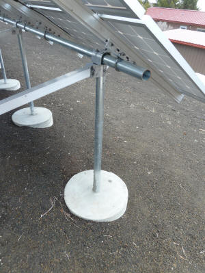
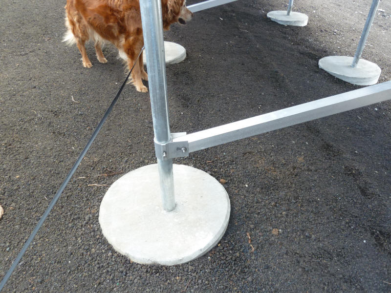
Front strut to horizontal rail attachment. |
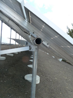
Getting the alignment of all the vertical struts right
might be the hardest part of this mounting system. |
Braces connecting the front and rear struts. |
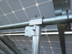
It looks like all of these T fittings have an
extra set of lugs for a side brace. |

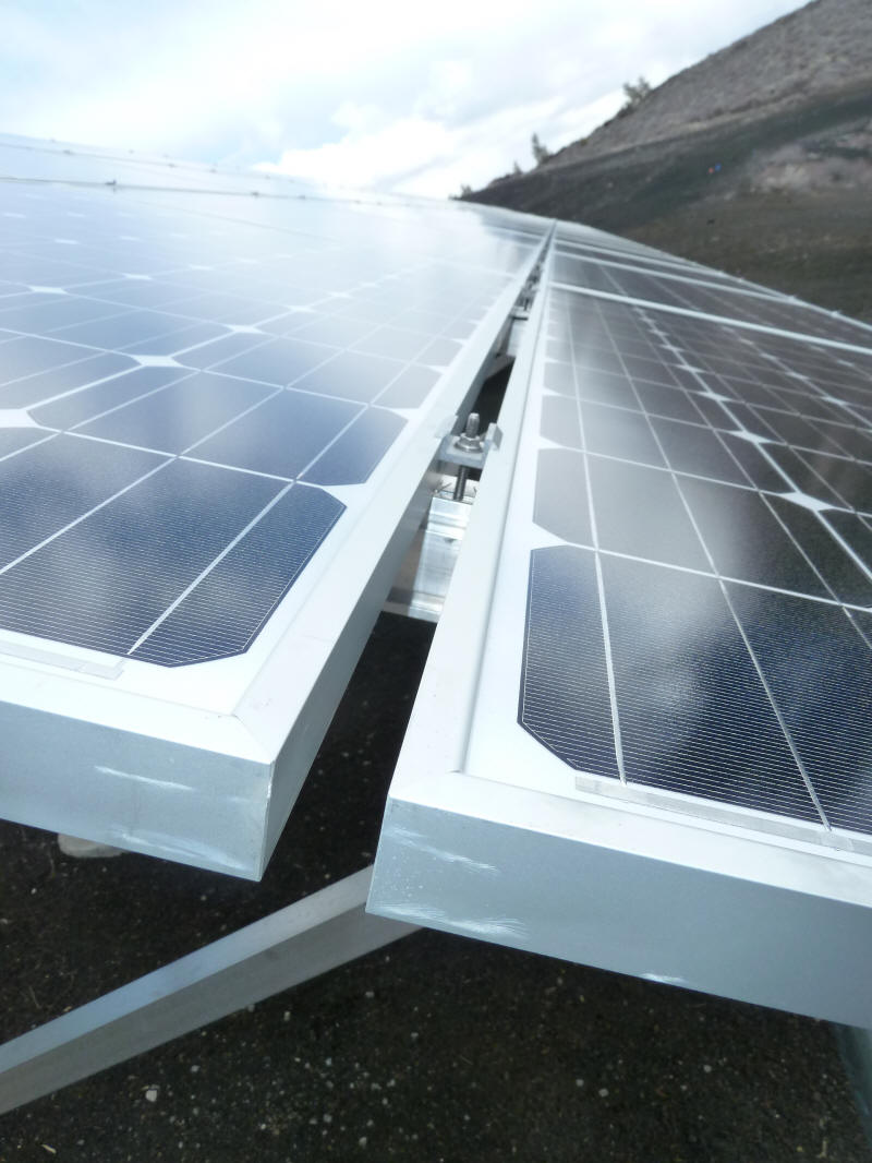
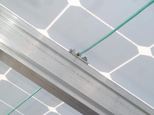
The clips that hold the modules to the rails. |
 |
A somewhat similar system made by ProSolar called GroundTrac...
,
Equipment and Wiring
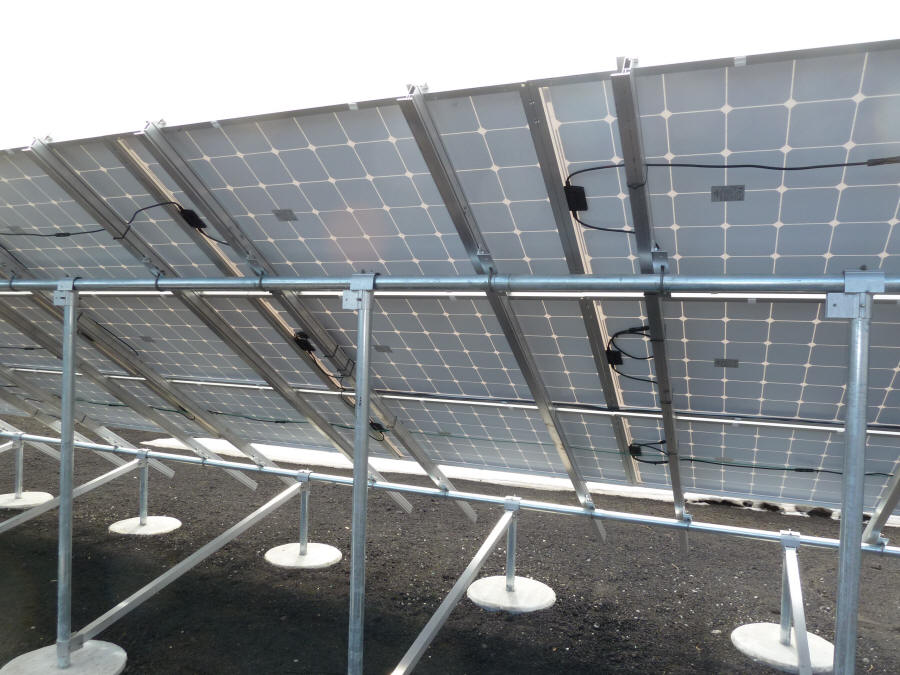
The PV array at Craters is very large (50 KW), and spread out over
several racks. These pictures are of the smallest of the racks, and
are more representative of what you might do for your house.
The PV installation is grid tied. Large "string" inverters are used
to couple the PV modules to the grid. The "string" means that a string
of several modules are connected in a series loop. In this
arrangement, which is used in most grid tied systems, the first module has
one wire connected to the inverter and the other wire connected to the 2nd
module in the string. The 2nd module is in turn connected to the 3rd,
and so on around the ring. The last module in the ring has its output
cable connected back to the inverter. Hooking the modules up in
this way minimizes wiring, and also allows smaller wire sizes to be used, as
the voltages add around the loop and the current stays constant. The
number of modules that should be connected in one strubg depends on the
panel voltages, the inverter specs, and the coldest temperatures that the
array sees. Most of these inverters can accept inputs from more
than one string of modules. The companies that supply inverters
usually have a calculator on their website that allows you to pick the
number of modules for the loop.
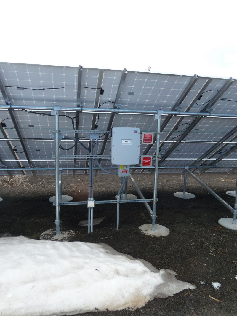
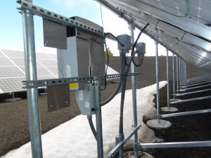
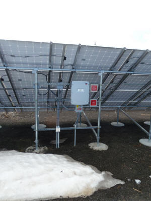
The grid-tie inverter used in this installation is an SMA. Note
that the DC disconnect, which provides for disconnecting the PV array at the
source, is built into the inverter which makes for a nice compact
arrangement and eliminates the need for a separate disconnect switch.
This may not be allowed in all locations.
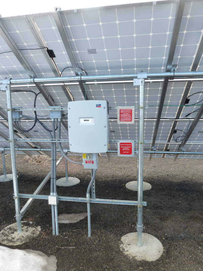
Grid tie inverter for the PV modules on this rack and on adjacent rack
(the underground conduits on the left carry DC from the adjacent rack).
Note how the equipment support rails tie right into the mount verticals
-- nice and simple.
Back view of inverter. |
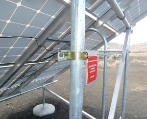
Tying equipment mount rail to verticals. |
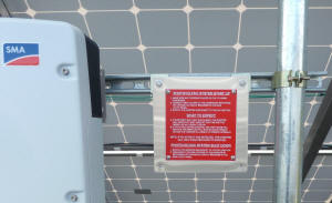
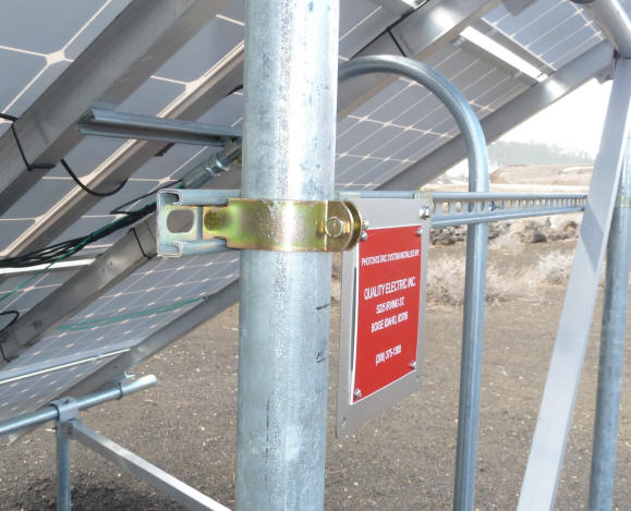
The required placard. |
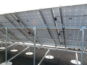
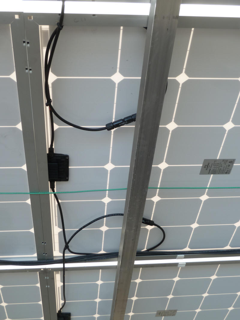
PV module wiring -- note the simple series
connection of the panels. |
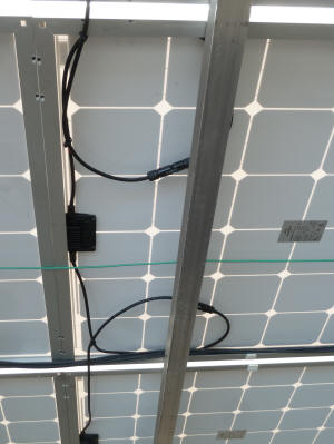
Another view of the wiring. |
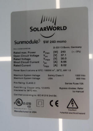
PV module labeling. The UL listing is
required for nearly all PV installations. |
Grounding. |
 |
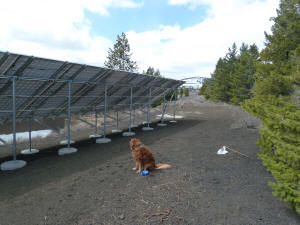
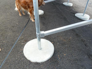
Kristy approved. |
In addition to the equipment shown in these pictures, there will need to
be a connection to the circuit breaker box, and an AC Disconnect switch that
is normally located near the circuit breaker box. The conduit coming
out of the bottom of the inverter is headed in that direction. The AC
Disconnect provides a way to insure that the PV array cannot power grid and
provides positive protection for anyone working on the system. The
grid tie inverter will automatically disconnect the PV array from the grid
in case of a power failure, but the AC disconnect provides an extra level of
protection that can be visually checked.
Gary April 12, 2011