Search
The Renewable Energy site for Do-It-Yourselfers
Thermosyphon Collector: Efficiency,
Flow Rate, Vent Size
|
This page covers some testing done on my
thermosyphon solar air heating
collector I use to heat my shop.
The testing covers these areas:
Back to the shop heating
collector main page...
Effect of Reducing Inlet and Outlet Vent Size
on Collector Performance
I use
this thermosyphon solar air heating collector to heat my shop.
Its a very nice, simple, cheap, easy to build, and efficient way to
provide space heating. A number of people have built variations on
this collector with good results.

About the only downside to this collector is that it requires fairly
large inlet and outlet vents in each collector bay in order to work
efficiently. These vents are time consuming to cut through the
wall, and have a visual impact on the inside space. This
brings up the question:
How much does thermosyphon collector
performance suffer as vent size is reduced?
If smaller vents could be used, it would also be possible to use a
large hole saw (6 or 8 inch) to cut the vent holes, which would save a
lot of time.
This test is an attempt to answer the question on how much you can
cut back on vent size and still get good performance. The
bottom line answer appears to be not very much.
|
|
Test Setup
The collector has 5 identical 4 ft wide bays. Two adjacent bays of the
collector are used for the reduced vent area test. The West bay is
the reference and always has the standard two inlet vents at 4 by 18 inches each
and two outlet vents at 4 by 18 inches each.
The vents on the East bay were tested in these three configurations:
- Config 1: Both the inlet and outlet vents are masked
down to a width of 7.5 inches so they are 4 by 7.5 inches instead of 4 by 18
inches. This approximates the area of a 6 inch round duct.
- Config 2: Both the inlet and outlet vents are masked
down to a width of 12 inches so they are 4 by 12 inches instead of 4 by 18
inches. This approximates the area of an 8 inch round duct.
- Config 3: Same as Config 2 except that one inlet vent
and one (opposite) outlet vent are completely masked off. This
approximates going down to just one vent per 4 ft bay.
The standard vent provides 1 sqft of inlet and 1 sqft of outlet vent for the
4 ft wide bay.
Config 1 provides 0.42 sqft of inlet and 0.42 sqft of outlet for the 4 ft
wide bay.
Config 2 provides 0.67 sqft of inlet and 0.67 sqft of outlet for the 4 ft
wide bay.
Config 3 provides 0.33 sqft of inlet and 0.33 sqft of outlet for the 4 ft
wide bay.
In all cases, all the measurements needed to calculate heat output are taken
on both the bay with the reduced size vents and on the reference bay -- this
allows an accurate estimation of the heat output drop due to the reduced size
vents.
| |
Thermosyphon Collector Design Rules
The "standard" vent size is based on the design ground rules for
thermosyphon collectors that I believe were formulated by Steve Baer
many years ago. The rules are:
- The vent area should be at least half of the cross sectional area of
the collector. So, if the collector is (say) 6 inches deep and 48
inches wide, then the cross sectional area is 6*48 = 288 sq inches, and
the vent area should be half that, or 144 sq inches. My collector
is exactly sized to the rule with two 4 by 18 (72 sqin) inlet vents and
two 4 by 18 outlet vent per 4 ft wide bay.
- The depth of the collector should be at least 1/15th of the height
of the collector. So, a 96 inch high collector should be about
96/15 = 6.4 inches deep. My collector is just short of meeting
this ground rule.
- The absorber should be a flow through design with low air
resistance but lots of surface area. I use 2 layers of metal
window (insect) screen, but others have used multiple layers of metal
lath, furnace filter media, ...
- The airflow path should be as smooth as possible to reduce air
resistance. I did worry much about smoothing the flow paths --
this would be an interesting area to explore.
|

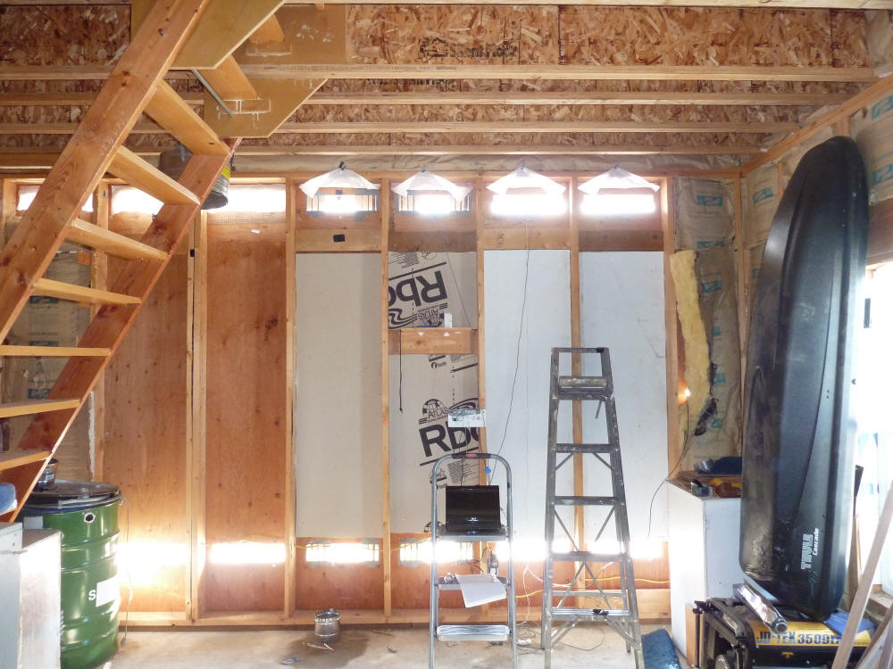
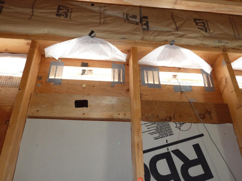
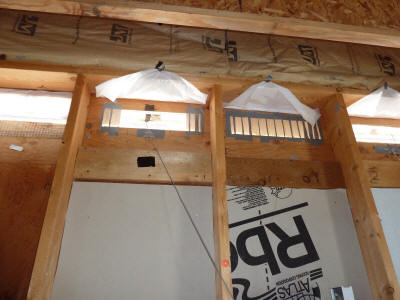
From the inside showing the inlet and outlet vents.
The right two vents and stud bays are the West (reference) 4 ft
collector bay. The next two stud bays are the East (test)
4 ft wide collector bay where the reduced sized vents are used. |

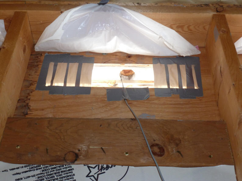
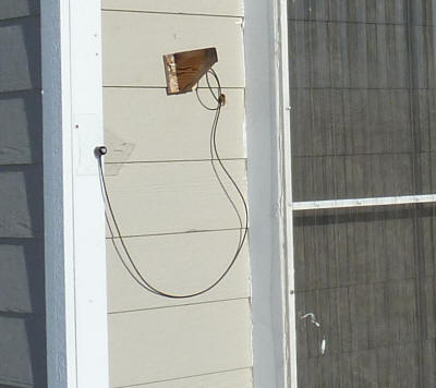
One of the exit vents masked down to 7.5 inches wide.
This provides about the same area as a 6 inch round duct. |

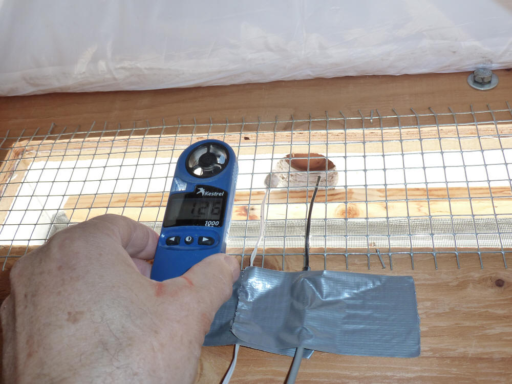
The low mass thermistor on the right logging outlet temperature.
The Kestrel wind turbine to the left measuring outlet velocity. |
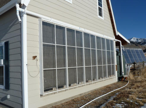
The Apogee pyranometer mounted on the same plane
as the collector. |
A nice day.
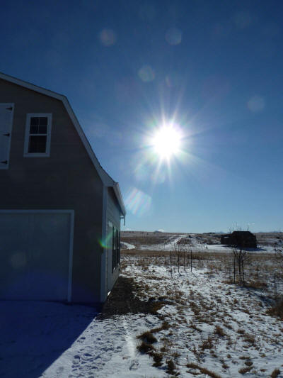
A nice clear day. |

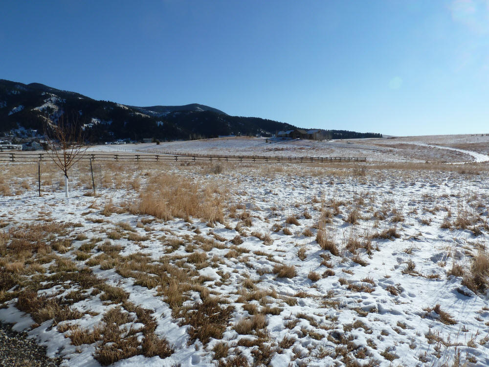
This shows the snow cover in front of the collector.
Normally by this time of year, there would be better
snow cover with a corresponding increase in reflected
sunlight and increased heat output. |
The three reduced size vent configurations tested:

Config 1: all vents masked off to 4 inches high by
7.5 inches wide. About same area as a 6 inch round duct. |

Config 2: all vents masked off to 4 inches high by
12 inches wide. Same areas as an 8 inch round duct. |
Config 3: diagonal 4 by 12 inch vents.
Only 1 inlet and 1 outlet vent. |
Results
The table below summarizes the results. It provides heat outputs for
both test bays for the three reduced size vents that were tried.
Temperature rise from inlet to outlet, and outlet vent velocities are also
provided.
| |
Temperature Rise (F) |
Velocity (fpm) |
Heat Output per bay (BTU/hr) |
"Efficiency" (%) |
| Vent Configuration |
Small Vent |
Standard Vent |
Small Vent |
Standard Vent |
Small Vent |
Std Vent |
Small Vent |
Std Vent |
| 1: Simulated 6 inch ducts |
80.1 |
68 |
177 |
127 |
4826 |
7055 |
44.4 |
64.9 |
| 2- Simulated 8 inch ducts |
67.6 |
69.7 |
148 |
118 |
5449 |
6719 |
50.3 |
62.1 |
| 3 - Diagonal 8 inch ducts |
75.3 |
65.9 |
184 |
123.5 |
3773 |
6649 |
35.2 |
62.1 |
It appears from the testing that any significant reduction in vent area does
decrease the heat output and efficiency of the collector. The best
small vent option is the simulated 8 inch diameter ducts for vents, but this
still results in a nearly 20% drop in heat output from the standard vents.
Going down to the equivalent of 6 inch diameter ducts cuts the heat output by
about 32% from the standard vents.
Using only one inlet and one outlet vent per collector bay with an area
equivalent to an 8 inch round duct cuts the heat output by 43% from the stand
vents.
As the vents sizes are reduced, the extra air resistance of the smaller vents
reduces the collector flow volume. Since there is less air flowing through
the collector, the air heats up to a higher temperature, which increases the
thermosyphon effect, and increases the air velocity through the vents -- this
helps to make up for the smaller vent area, but, as the heat output numbers
show, its not enough to compensate for the smaller vent area.
Another way to look at this is that the lower collector flows and higher
collector temperatures that the small vents cause result in a hotter collector
that loses more heat through the glazing to the outside.
The chart above is an attempt (possibly a stretch) to generalize the effect
of reducing vent area on heat output. The plot shows the drop in relative
heat output as the vent area is decreased compared to a standard vent area.
The standard vent area follows the design ground rule stated in the table above.
For example, cutting the vent area in half reduces heat output to about 75% of
what it is with full size vents.
Based on the results above, I would expect that increasing the vent size from
the "standard" vents would yield some further increase in heat output.
This is logger plot for temperatures and sun intensity -- the table above is
based on values from this plot and from hand recorded vent velocities.
Explanation of plot:
Standard vent outlet temperature (F) -- solid black
Small vent outlet temperature (F) -- dashed red
Inlet temperature (F) -- long dash green
Solar intensity (watts/sm) -- solid blue
Time Line:
11:20 am to 11:44 am -- Small vent bay has both inlet and
outlet vents masked down to 4 inches by 7.5 inches -- about the same area as a 6
inch dia duct.
11:48 am to 11:54 am -- Small vent bay has both inlet and
outlet vents masked down to 4 inches by 12 inches -- about the same area as a 8
inch dia duct
12:02 pm to 12:10 pm -- Small vent bay has one inlet and
one outlet at 4 by 12 inches with other inlet and outlet blocked -- about the
same as having one 8 inch duct per bay.
Note that the major dip in temperature on the red line at 12:03 pm was caused
by the temperature sensor slipping out of position for a few minutes.
Ambient temperature started at 43F at 11:30 am and went up to 44F by 12:45
pm.
An air density of 0.061 lb/cf is used -- this is based on our altitude of
5000 ft and an average temperature in the collector of about 85F. This
calculator is used for the density estimate...
The velocity measurements are taken in the center of the vent area using a
new Kestrel turbine anemometer. To account for the drop off in
velocity toward the edges, I have factored down the center velocity by 7% -- the
7% is based on measuring velocities toward the edge of the vent with the same
Kestrel meter.
Solar intensity measurements are taken using the logged values of a nearly
new, calibrated Apogee pyranometer.
Heat output for the bay in BTU/hr is calculated as:
Heat Out = (Vent Area)*(Vent Velocity)*(Kvp)*(Air
Density)*(Tout - Tin)*(60 minutes/hr)
Vent Area is the total outlet vent area in sf
Vent Velocity is the center of vent velocity in ft/min
Kvp corrects for the velocity profile of the air leaving
the vent -- I am using 0.93 based on measurements around the edges.
Air Density is the air density in lbs/cf -- sea level is
0.075 lb/cf, but for our 5000 ft altitude and average collector temperature it
drops to 0.061 lb/cf
Tout is the exit vent temperature in degrees F
Tin is the inlet vent temperature in degrees F
60 min/hr converts the BTU/min to BTU/hr
Measuring Collector Efficiency
In addition to estimating the effect of reduced size vents, another aim was
to get as good an estimate for the collector efficiency as possible with the
instruments I have. I took the following steps to try to get good
efficiency estimates:
- Temperatures were measured with Onset Computer
thermistors having a specified accuracy of 0.25F over the range of interest.
- The outlet vent thermistors are low mass, faster
reaction versions to reduce lag problems.
- Sun intensity measured with a new, calibrated Apogee
pyranometer mounted in the plane of the glazing half way up the collector.
- Very consistent and steady sun on this day, and
measurements taken in stable midday conditions.
- Several trials for each measurement point -- these
showed good consistent results.
- Air density corrected for altitude and temperature.
- Air velocity measurements taken with new kestrel
turbine anemometer (each anemometer is
factory checked for accuracy).
- Velocity profile over the vent area is accounted for
using a correction factor.
One factor I have not taken into account is any dependency of the Kestrel
velocity reading on air density. Our air density at 5000 ft elevation is
down about 17% from the sea level density. Since the Kestrel is a turbine
driven by aerodynamic lift and drag forces, one would think that the velocity
reading might be effected (reduced) by our lower air density. Kestrel
responded to an inquiry on this saying that they do not believe the velocity
readings at altitude are effected, but I'm still uncertain about this. If
you have knowledge or experience in this area, please let me know what you
think. If the velocity readings are lower at altitude, then
the effect would be to increase the heat output and the efficiency from the
numbers in the table above.
Note: Kestrel answered this question, and have convinced me that because the
turbine does not extract any energy from the flow (unlike a wind turbine
generating power), and the bearings are very good, and the turbine weight is
small --that the drop in air density with altitude does not effect the
rotational speed of the Kestrel turbine.
Thanks to Nick Pine and Ben Neilsen at Kestrel for getting this question
answered.
Of the sources of error, the average vent velocity is probably the most
significant. Measuring air velocity accurately on any solar air heating
collector is difficult, and the relatively low velocities over large vent areas
make the thermosyphon collector measurements even more difficult.
In the end, I think that the efficiencies in the 62 to 65% area under the
moderate winter conditions are reasonably accurate. I also think that this
kind of efficiency in this very simple, very cheap collector is not much short
of simply amazing, and are quite competitive with high quality commercial
collectors.
One thing to keep in mind is that efficiency varies with with solar intensity
and with the temperature difference between the collector and the ambient air
(and a few other things), so the 62 to 65% efficiency measured in this test is
just one point on an efficiency curve -- a point that is typical of sunny day
moderate winter conditions. On warmer days the efficiency would be
higher and on colder or less sunny days the efficiency would be lower.
If you have any suggestions, comments, corrections ... I'd like to hear them.
Measuring Flow Rates
Its interesting to note that the flow rates achieved by this collector are
quite respectable even by fan forced collector standards. The flow rate
for one 4 ft wide bay of the the standard vent size is:
Flow Rate = (Vent Area)*(Vent Velocity) = (1 sf)*(127 ft/min)
= 127 cfm
This gives a flow rate per sqft of collector of (127 cfm) / (32 sf) = 3.9 cfm/sf
-- this is higher than most fan forced collectors achieve.
Using The Back of Collector as Large Radiant Heating
Panel
Since the back wall of the collector IS the south wall of the shop, and since
the back wall warms up when the sun is shining on it, there is some heat
transfer from the collector directly into the shop that is independent of the
main heat transfer through the vents.
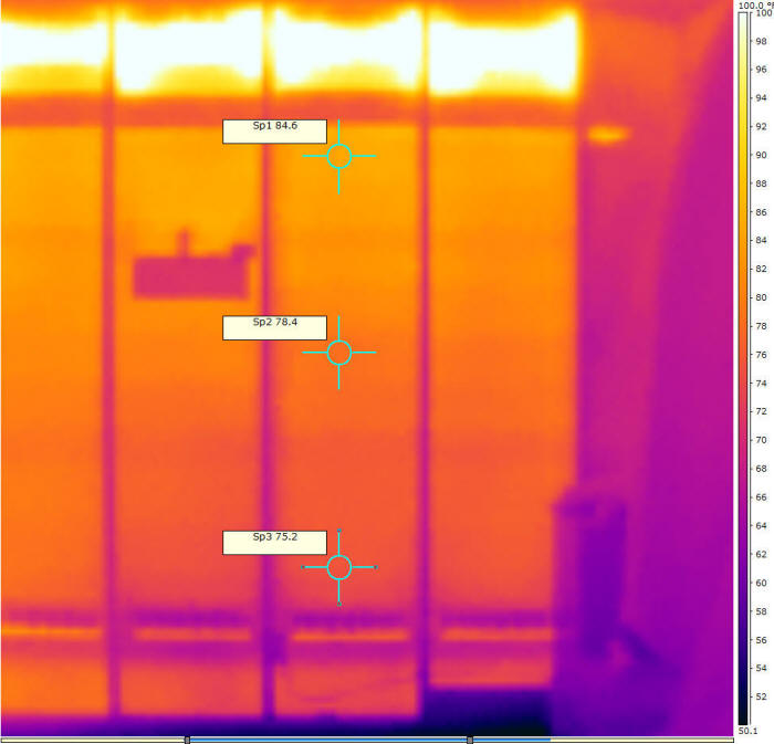
The IR picture just below shows the south wall of the shop with the collector
operating. The wall is heated to about 85F at the top, 78F in the middle
and 75F near the bottom. The non-heated shop wall temperature at this time
was about 55F.
So, there is some heat transfer to the shop from the back wall of the
collector by air convection over the heated wall and also by radiation into the
shop space.
I could not quickly find a good method to calculate the heat output of the
big wall radiator, but a quick look indicates that the air convection alone is
more than 2000 BTU/hr.
Note that when I did the efficiency measurements shown in the section above,
I did insulate the back of the collector so that all of the heat output would be
via the vents.
The downside of leaving the wall behind the collector uninsulated is that the
heat loss is greater when the sun is not shining on the collector. The R
value of collector glazing plus the wall itself might be about (R1 glazing + R1
wall air films + R1 wood) = R3 -- about the same as a low-e, double glazed
window.
So, in most circumstances it probably makes sense to insulate the wall behind
the collector. The exceptions might be if you don't care how much the room
cools when the sun is off the collector, or if you can work out a movable
insulation scheme so that the wall can be insulated when not collecting.
Gary
January 3, 2012