Search
The Renewable Energy site for Do-It-Yourselfers
Building a Solar Air Heating Collector from
Soda-Pop Cans
Greg West
<Greg -- some questions for
you below in this red font>
This solar air heating collector uses recycled aluminum
soda pop cans for the absorber. The pop cans have the tops and bottoms drilled
out, and are assembled into vertical columns that the air passes through. The
black painted soda pop cans are heated by the sun. The solar heat is
transferred to the air passing through the columns of can.
A manifold at the bottom supplies room air to all the can
columns, and a similar manifold at the top of the collector collects the heated
air for distribution back to the room.
The combination of uniform air distribution to the whole
collector and the large amount of heat transfer area from the cans to the air
makes for an efficient collector. My collector also uses Twinwall polycarbonate
glazing -- this is a type of double glazing that reduces heat loss and increases
the efficiency of the collector.
So let’s start from the beginning. I want to first thank a
guy that goes by my2cents0 on YouTube for directing me to the Hungarian website
that led me to an engineer whom I only know as Zoli. He actually speaks better
French than Hungarian J. I want
thank Zoli for his upmost patience with me on this project, I bugged him to
death back and forth for nearly three months to make sure I was doing everything
right.
Overview
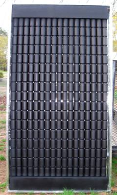
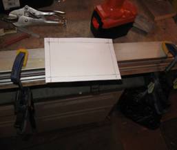
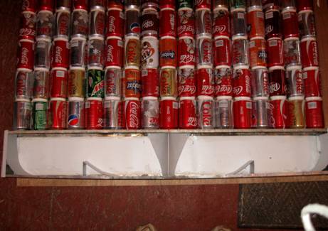
These are my cans siliconized together with the top
manifold on and the bottom manifold you see on the table. My panel core, is 17
cans wide and 17 cans tall -- this was all I could fit into a four by eight foot
insulated box made from Polyisocyanurate insulation board (polyiso). The
outside of the collector measures 4 ft by 8 ft. The header caps are 44 ½” with
½” bends on all ends.
I drilled the manifold holes at 54mm dia. and spaced at
66mm on center and came to find out the can columns would “just fit”. Maybe
67mm O/C might work better just so things won’t be to tight. Using 67 mm
spacing will make the space between holes 11 to 12 mm which, I think, will work
fine. On the next collector I will use the 67 mm spacing between hole centers.
Start 10mm from the header cap end before you start laying out and drilling. I
drilled the bottom holes in the cans out at 44mm and the top ones at 51mm. You
need to be very careful with the tops, because the hole saw will just fit, no
room to mess up J.

When cutting the cans with the hole saws I used in a drill
press which was a learning experience in itself. It took a little while and
several near miss flying objects to get the hang of it. You would be amazed how
fast a hole saw can take something right out of your hand. So, safety first.
Wear safety glasses and leather gloves that some cotton jersey gloves will
fit into. The cans will heat up rapidly while cutting the tops and bottoms out.
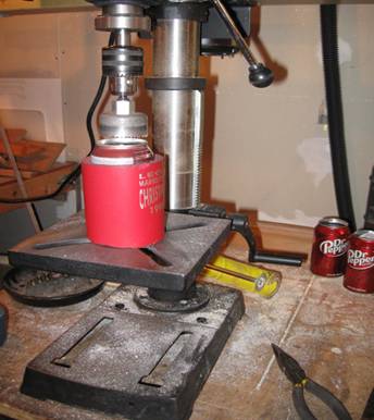
Building the Can Columns
At first, I made some wooden jigs to hold the cans while
cutting on the drill press.

I used a small rotary saw to start a hole for
the diameter of the end of can I was working on. Then, believe it or not, I
took a smallstraight cut router bit in my drill press and cut out the rest of
the hole
.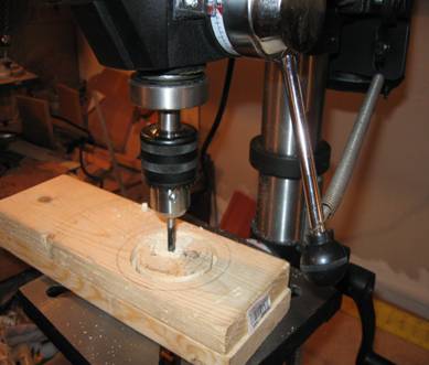
If you have a steady hand, set the depth on your drill
press this is pretty easy to do. Notice my extra hand, a screen door spring
holding the router bit to it’s depth. Oh my, necessity really is the mother of
invention. I made the jigs out of large stock of two 1” x 4” blocks of wood
glued together, then cut them down to a size that was easy to handle.
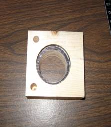
This jig is for the can tops. I marked the inside
shoulder to be more plain and cut to a depth just enough for the cans neck to
fit into. I made a similar holder for the can bottoms.
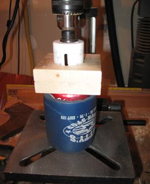
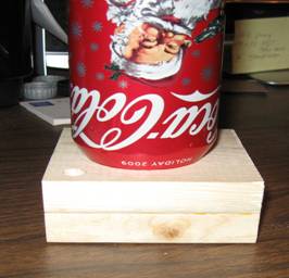
After all this trouble, I actually found out it was easier
to drill the can tops and bottoms out by just putting the can in a cozy holder
as shown in the picture, and doing the drilling free hand. This is where the
leather cloves and cotton jersey ones come in. As I said before, the 51mm hole
saw will just fit the can inside the can rim. You have to be very careful here
-- most times this is where you going to mess up
J. I ran my drill press at it’s
medium speed and used Lenox hole saws -- they cut pretty well. Let the can
spin a little if it wants to. Hold the can near the top with one finger on the
can top close to the saw, and the rest of your fingers resting around the
cozy. The can will get hot fast.
Cut out the bottoms of the cans using the 44mm hole saw.
This is a breeze after the first few cans. Just remember to let the can spin a
little as you cut it if it wants to. If you try and hold the can to tight the
hole saw will twist the can inside the cozy -- if this happens, the can will be
scrap because it will cause the can to wrinkle and although you may not see the
very minute crack in the can it will be there, I sprayed primer on one can here
as an example.
<Greg -- could you cut out
both the tops and bottoms with the 44 mm saw to make things easier? Or, will the
44 not work on the bottoms? >
The ring you see around the can will become a leak down the
road if you use it because of the expansion and contraction from heat over
time. Soda cans are only 10 microns thick, so it won't take long to develop a
leak.
Notice the bricks at the lower right of the photo, these
are what I used to keep pressure on the cans after the silicone was applied.
Some cans with the tops and bottoms cut out.
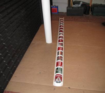
I used a 3” PVC pipe cut in half to hold my can tubes
while the silicone cured. One note, buy an end cap for the pipe, it will make
things a little easier. I’ll do that next time. Cut the end cap in half and
glue it to your pipe. 1”x 4” boards nailed together will work just as good I
think but I have not tried that yet.
Here’s the photos of the can tube construction, I just put
silicone around the small end of the can, pressed them together while in the PVC
tube and while using one finger to smooth the silicone joint I used my other
hand to turn the tube as I went along.
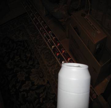
You can see at the left one tube already complete in its
PVC holder.
Let your hand rest gently on the left can while turning the
assembly with your other hand, thumb and fore finger.
There’s that brick again, I was doing this in my living
room floor because it was to cold to do it out in my shop. If incline the tube a
little the brick will have enough pressure to keep everything in place until the
silicone sets. I did this until I had a stack 17 cans tall and 17 wide to fit
the 44.5” wide manifold plates I had drilled out for them. Ok, you have your
tube stacks made. If your collector is not 4 ft by 8 ft, you will have to work
out the number and length of can columns for the size you are building.
Building the Manifolds
First I took a 1” x 4” and measured out the dimensions
given to me by Zoli from his SketchUp drawing
<Greg -- if you can give me a
link to the SketchUp drawing I can include it -- or if we have the file itself,
we can just include it.>
and drilled a test manifold to make sure everything would
fit. It was tight. Since everything over in the UK etc. is metric that is what
I used. The closest hole saw I could come up with for the cans was a 54mm. The
plans called for 55mm holes spaced 66mm on center. I started 10mm from the edge
of the manifold and did my layout. I think that spacing the holes 67mm on
center would not hurt on the manifold layout, as there sufficient room to do
this.

I just clamped a scrap of 1 x 4 under the manifold plate
while drilling free hand. This worked out well for me. Here’s a photo of
drilling the cans free hand. Be very careful.
<Greg -- is this something
that happens only on the bottom/top can in each column?>
After I had done
all this I fitted the can tubes into the top and bottom manifold plates and used
silicone to seal them in place.

Don’t be afraid to
use plenty of silicone here, but don’t block the air way. After this measure
what you have. Then cut aluminum flat plates to take up the room to make
can/manifold assembly fit into the 4’ x 8’ Polyiso housing, they ended up being
approx 6.75" tall by 3.5” deep 44.5” wide.
<Greg -- Its not clear to me
where the "flat plates to take up the room" fit in?>
The photo above is of the new style manifold with air
disrupters installed and end caps which I had to make myself.
<Greg -- do you know if the
disrupters were added because they observed uneven air flow in the columns? Or?
I would have thought that a
manifold of this type would do a good job of distriuting the air evenly to the
columns without any disruptors or deflectors -- did they actually see evidence
that the distribution was uneven? >
I made these out of aluminum house trim coil and had to cut
the radius on the ends to make them fit on each end of the manifolds.
Making the end caps
I did this on top of my saw table just using some clamps
and straight edge. Just bend the sheet up with your hands then tap along the
edge with a hammer and you will come out with a nice edge.
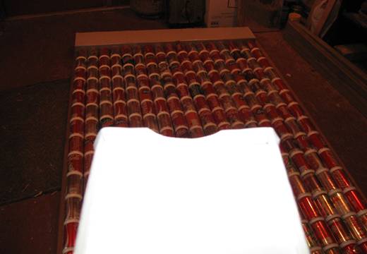
Painting and Final Assembly
Here’s a photo of the painted pane core. Do the painting
outside of your shop or house.

You want the core housing to be reflective so that any sun
that passes by the core will be bounced back onto the core.
Photo of the intake with cover I made from aluminum and
mounted a 6” duct fitting to it, I did the same for the outlet.
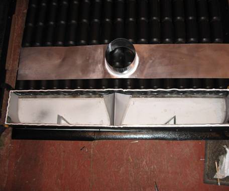
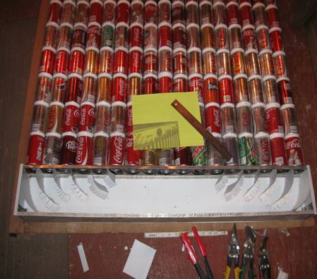
Photo of outlet as you can see I only had a picture to go
by, just simple air deflectors. Zoli said it looked good to him
J
Photo of the core, 3” pipe and cans
<Greg -- should we move this photo
up a ways where you are putting the can columns together?>
Some photos of housing.


I protected all exposed polyiso board with Aluminum tape,
the inside corners also.
<Greg -- any thoughts on how
the polyiso housing will stand up to the weather? Have they been using this
over in Europe?
Do you see any problem with
using exterior plywood with a thin layer of polyiso over it?>

I then used silicone on all inside edges of the tape just
to make sure they didn’t work loose over time as I’ve found out can happen.

Photo of collector in it’s housing. You can see the reflection from the back of
the housing here.

And this photo of
collector on it’s side in my shop.
<Great pictures!>
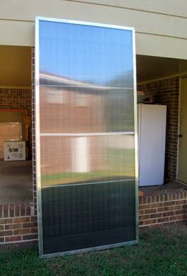
And the finished collector below. The strip you see in the
center is to keep the panel from expanding over four feet wide which it would do
when heated up. I also have 3/8ths inch aluminum rods in place to help support
the twin walled polycarbonate panel in case it is mounted on the roof.
<Greg -- I think the rods
would be a good thing even for vertical collectors, as the twinwall tends to bow
in as the collector warms up if there are no supports>
This collector can also be mounted vertical or horizontal
on the south side of your home and it will work fine.
The only test I have run so far with Gary’s help was with
the collector laying on it’s back on saw horses with the glazing just held on
with some quick clamps. The test was promising with the collector running at
91cfm at a 60 F degree temperature rise. I would like to see it run at 100cfm at
around a 50 to 55 F degree temp rise but that means a more powerful and louder
fan which would require a muffler of some sort.
<Greg -- seems like the
current fan is doing a good job -- if its not noisy, I think I'd keep it. A 60F
rise is (I think) OK >
One more note on the polycarbonate panel. The people at Tex
Supply told me to be sure and cut the panel one half inch shorter than the
collector frame all the way around because it would expand when heating up and
they were right, it did -- a lot. To seal the glazing to the panel I used
polyurethane foam in case anything were to go wrong down the road I can get into
the panel easy.
<Greg -- I gather that this
is half an inch less in width and height for 1/4 inch of clearance on all sides?
>

Not a bad looking panel for my first one, can’t wait to
build another J
<What a handsome dude!>


Greg September 5, 2010
<Greg -- you need to decide
if you want to list an email for questions -- people go both ways on this --
can't remember what you did for the other project?>
Can Collector ResourceS:
Zoli's site?
Gary's
collection of can collector links...
A commercial
version of this collector is made by
CanSolar...
Others???