Search
The Renewable Energy site for Do-It-Yourselfers
Charging the Elec-Trak Using a
Grid-Tied PV Array
|
One of the major aims for the Elec-Trak project is to be able to use
the Elec-Trak battery pack for power
during power outages AND to be able to recharge the Elec-Trak pack from
our grid-tied PV array.
This section covers our somewhat brute force method for charging the
Elec-Trak from the PV array.
Back to the Elec-Trak Table of Contents... |
|
Overview
We have a 2.15 KW grid-tied PV array
that helps offset some of our power use. Our PV array is grid-tied and
uses the Enphase micro-inverter system with one micro-inverter on each PV panel.
Since this is a grid-tied PV system without battery backup, when the utility
power goes down, our PV array goes down a well -- even if the sun is shining, we
get no power. Grid-tie inverters are required to shut down when they sense
that grid power is no longer there -- this is a safety feature meant to protect
utility workers working on the line.
It is possible to do grid-tied systems with battery backup. In the case
of a power outage, these systems disconnect from the grid and supply limited
power to the house from their batteries via the
inverter. We elected not to do this because
the systems are considerably more expensive, and because of the high cost of
replacing batteries over time. The added costs of buying and replacing
batteries can all but wipe out the savings from reduced power usage, and this
just did not seem worth it given that our power is pretty reliable.
So, now with the Elec-Trak we have a large set of batteries that is earning
its keep on mowing and snow blowing tasks, we asked ourselves if there is not some
way to 1) use these batteries to power the house in emergencies, and 2) charge
the batteries with our existing PV array?
The first item of powering a few critical house loads during an emergency
from the Elec-Track batteries is a pretty easy yes, and is covered
here...
The 2nd item is more challenging. The solution we came up with
for using our current PV array to charge the Elec-Trak during a power outage is
a bit brute force, but is pretty simple and pretty easy to implement for our
type of system. In a nutshell, we bought an off-grid style charge
controller, and then rewired six of the PV panels to suit the charge controller.
The charge controller then charges the Elec-Track battery pack. For the
duration of the power outage, we effectively convert a portion of our grid-tie
array into a typical off- grid array -- details below.
This sounds like a somewhat complex approach, but it actually is surprisingly
straight forward to do, and is relatively inexpensive. The only
significant expense is the charge controller, which was $450. While
rewiring the PV modules seems like an involved thing to do, its actually
straight forward, and the time to go from grid-tie configuration to off-grid
configuration is under half an hour. What this gives us
is a reliable, long term, quiet, emergency power source, AND it does not require
us to maintain and replace a separate set of batteries that would be just
sitting there doing nothing 99.9% of the time -- we just use the same Elec-Trak
batteries that are already earning their keep with mowing chores.
The Hookup
| |
Safety Warning and Disclaimer
There are serious safety issues involved with wiring PV systems.
The voltages can be high, and potentially lethal. When you
couple electric shocks with working on the roof, there is an obvious
potential for serious accidents.
PV systems have the added hazard that even when the grid power is turned
off, the system can be "live" and present a serious shock hazard --
hundreds of volts on some systems.
I want to make it very clear that I am not an
electrician, and I take no responsibility whatever for the correctness
of the wiring hints below -- you need to do your own homework!
http://www.builditsolar.com/Contact/legal.htm
|
Charge Controller Input from PV Modules
The heart of the system that charges the Elec-Trak from our PV array is the
Xantrex MPPT60-150 charge controller. This charge controller will
accept a wide range of PV panels as input and will charge a battery packs that
are 12, 24, 36, 48, or 60 volts. It is one of a few charge
controllers that will charge a 36 volt battery pack like the one in the
Elec-Trak. It is also an MPPT (Maximum Power Point Tracking) charge
controller, meaning that it adjusts the PV module input voltage to the point
where the PV panels will produce the most power for the prevailing sun conditions.
Similar flexible charge controllers are made by Outback, Morning Star,
and probably others.
The charge controller requires that its input voltage from the PV panels fall
within a range of voltages that the charge controller is designed to accept. You
must configure your PV modules into series strings whose where voltage for the
string falls within the charge controllers allowed
voltage -- typically, these are strings of 2 to 5 modules depending on the
characteristics of the modules. Xantrex (Schneider) provides a
tool that will allow you to pick the type of module you have and the voltage
of your battery pack, and the tool will give you the number of modules that need
to be connected in each string, and how many strings are allowed. In our
case (REC 215 PV modules) it is possible to use strings of either 2 or 3
modules, and anywhere from 1 string to 6 strings can be accommodated.
We decided on 2 strings of 3 PV modules each. This uses 6 of our 10 PV
panels and provides up to 1290 watts charging with full sun. If there is a
need in the future, we could go to 3 strings modules for 1935 watts.
Rewiring the PV Panels
So, normally on our PV array, the two leads from each PV panel are plugged
directly into the micro-inverter for that panel.
For the new emergency power setup, the first 3 PV panels must be wired into
one series string, and this string is hooked up to the charge controller. Likewise, panels 4 through 6 are wired into a 2nd series string and also hooked
up to the charge controller in parallel to the first string. The nominal
string voltage is about 100 VDC.
All of the PV panel connections on our array are made with the standard MC4 connectors.
So, the "rewiring" is just a matter of unplugging MC4 connectors from one place
and plugging them into another place. The MC4 connectors snap into
place, and it is helpful to have the little tool that releases the snaps when
undoing the connections. The wiring sketch below shows the connections as
we made them.
Note that a new cable is needed to make the connection from the negative lead
of the first PV panel to the charge controller, and a 2nd new cable to make the
connection from the positive lead of the last panel in the string to the charge
controller. This is most easily handled by buying an
MC4 extension
cable, and cutting it in half -- each half gives you one of the new cables.
The 2nd string is done in the same way, and needs another MC4 extension cable
cut in half.
Our PV array is ground mounted, so access for rewiring is easy. It
would be an interesting challenge to work out a way to do a roof array without
actually going on the roof -- any ideas?
Charge Controller Output to Battery Pack
The Xantrex charge controller we are using accepts battery packs of 12, 24,
36, 48, or 60 volts. When the system is started up, the Xantrex normally
detects the battery pack voltage and adjusts accordingly, but if not, you just
set it to the nominal voltage of your battery pack.
The charge controller output cable simply plugs into the same outlet on the
Elec-Trak that the old external charger plugged into.
The charging cable from the charge controller to the Elec-Trak includes an
inline 50 amp fuse. The charge controller will actually do up to 60 amps,
but the 50 amp fuse provides more than enough current for our PV setup, and
keeps the wire size down a bit.
The grey cable is from the charge controller, and terminates in the 3
prong grey plug that was
used to plug an external charger into the Elec-Trak.
So, basically, the PV charge controller just plugs into the Elec-Trak in the
same place the external charger used to.
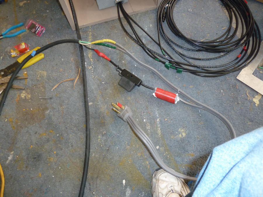
The extra yellow and green wires were a work around for a temporary problem and
are not part of the regular system.
Mounting and Wiring
The charge controller must be protected from rain, so it is mounted in a
simple, portable plywood enclosure. The enclosure is just large enough to
meet the required clearances around the charge controller for ventilation.
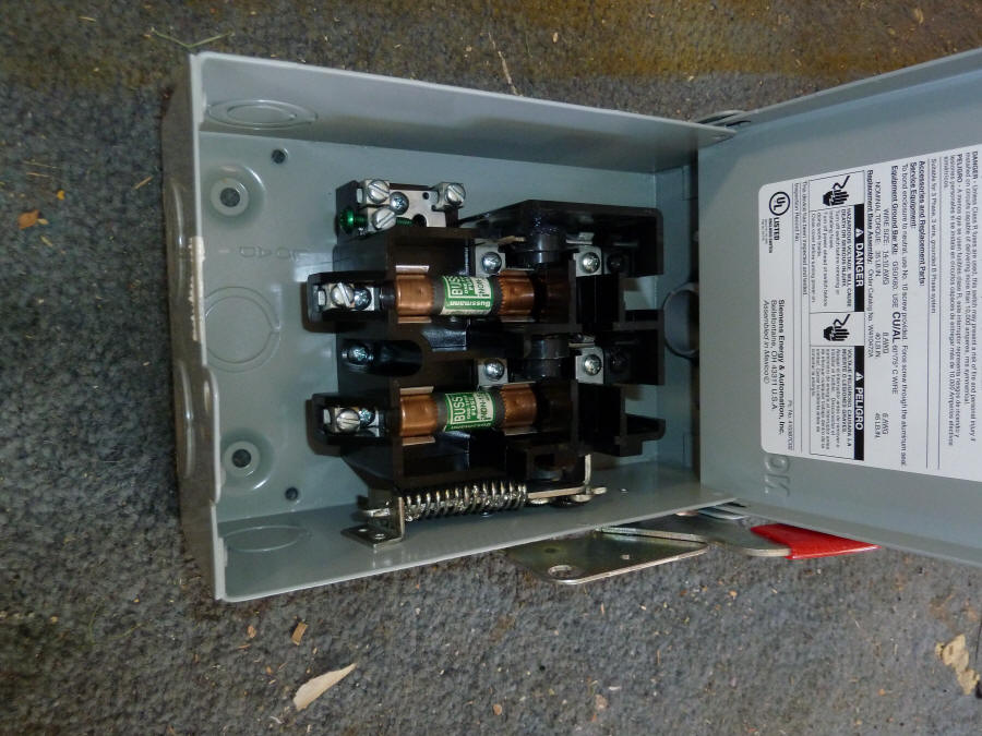
A fused disconnect switch is mounted below the charge controller. The
switch disconnects the PV modules from the charge controller and also provides
overcurrent protection for each string. The fuses and switch need to be DC rated
to the appropriate values.

The Xantrex charge controller mounted in its little shelter
out on the PV array. It hangs on one of the PV array supports.
During times between power outages, it lives in the barn.
|

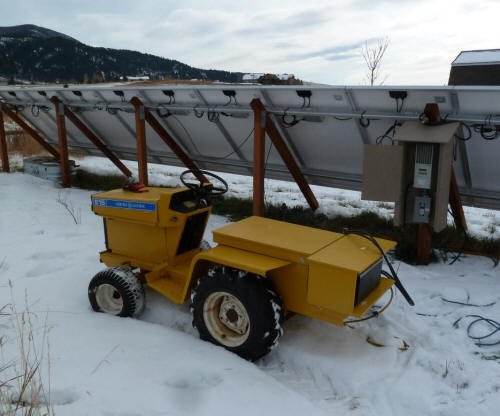
The Elec-Trak battery pack being charged by the PV array while
the Elec-Trak supplies 120VAC to house from the inverter/charger (which
the box on the back of the Elec-Trak) |
Wiring and Mounting the Charge Controller and Disconnect
The charge controller, disconnect, and its plywood shelter are normally
stored out of the weather in the barn. When there is a power outage,
we take it out to the PV array and hang it on one of the PV array support posts.
The wire connections to the PV array and battery are permanently connected to
the charge controller and just coiled up and stored with it.

The weather housing for the charge controller
made from plywood and MDO. |
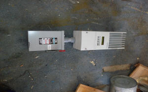
The Xantrex MPPT charge controller
mounted to the DC array fused disconnect. |

The disconnect with a DC rated fuse for
each of the two PV panel strings. |
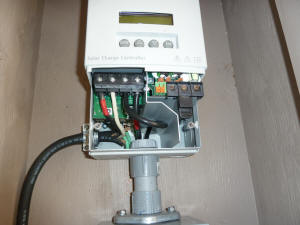
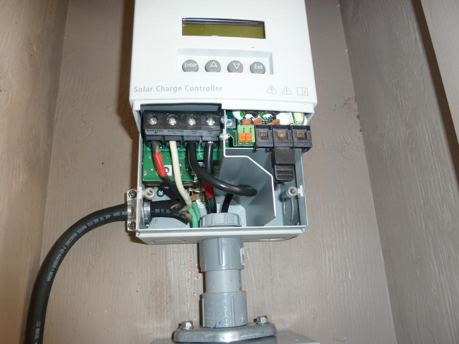
The charge controller wired.
The wire going into the conduit is going to the PV
array via the disconnect.
The black cord is the #8-3 wire going to charge
the battery pack. |

The wired disconnect switch.
The 4 wires coming out the bottom are going to the
two PV module strings. |
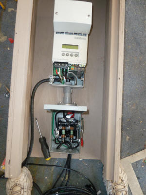
Completed charge controller assembly. |

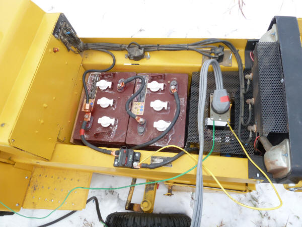
This is the somewhat untidy hookup of the
charge controller to the Elec-Trak pack.
The three prong plug is what my Elec-Trak
was setup for
to plug the battery charger in.
The black bulge is an inline 50 amp fuse as
required by the charge controller in its battery
charging line. |
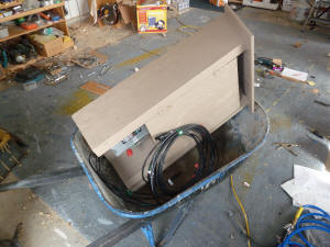
The whole package fits in a wheelbarrow
for easy transport out to the PV array
for a power outage. |
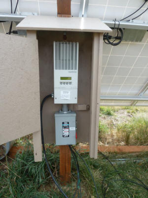
The charge controller and disconnect mounted
out at the PV array. |
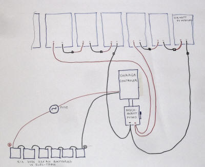
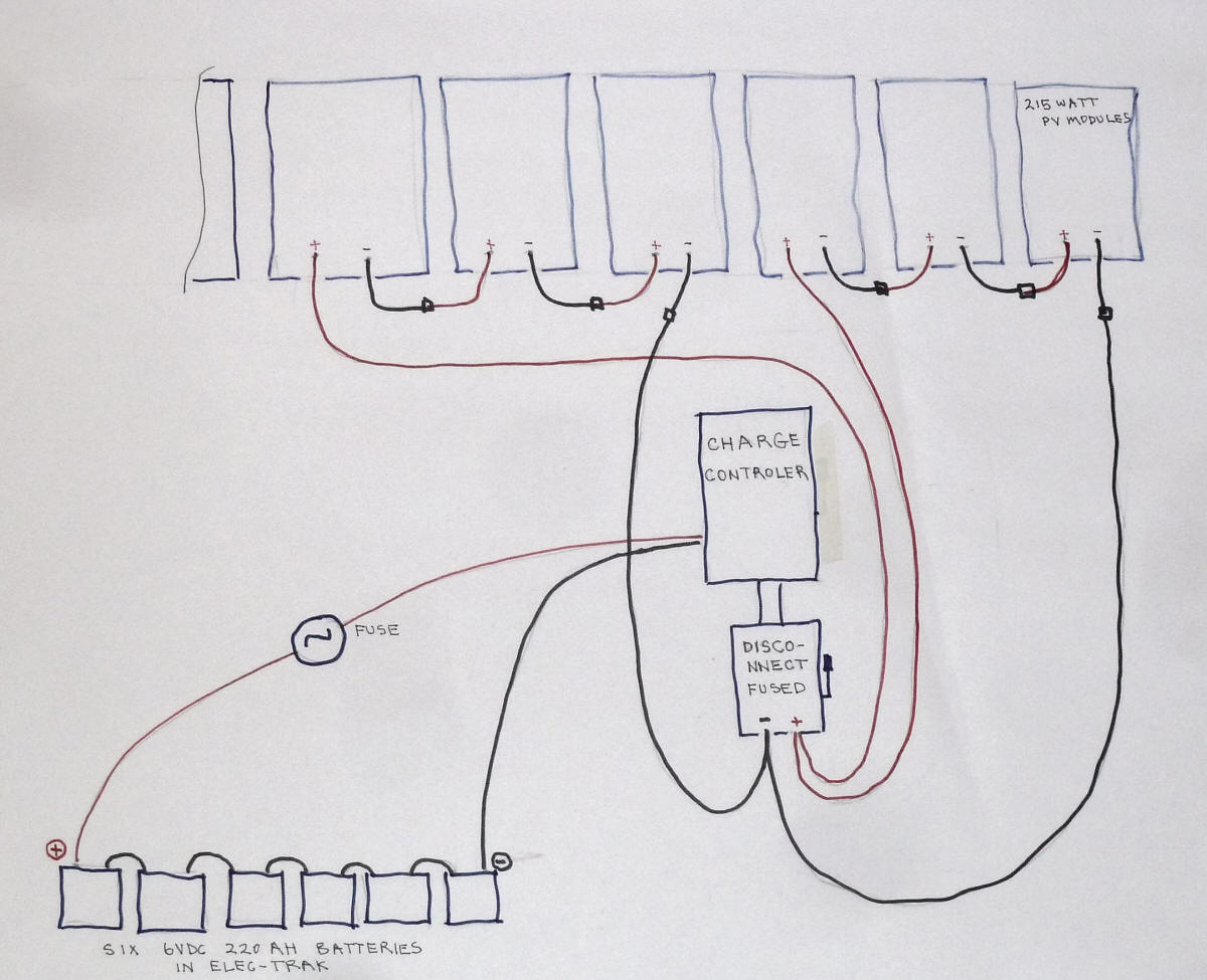
A very rough wiring diagram.
The actual sequence in which the connections are made and switches flipped
etc. are covered in the Test section just below. It is important from
both a safety and protection of equipment point of view to do the change over
from grid-tie to emergency power and back in the right sequence.
The Test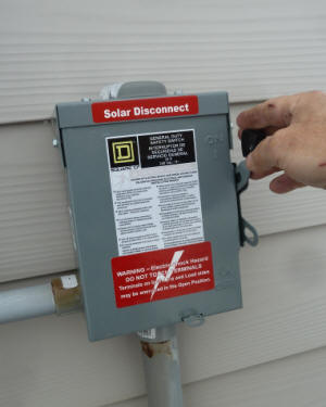
Since we don't get power outages very often, I went ahead and did a simulated
power outage so that we could make sure the system actually worked and get the
sequence down. So, here is the whole sequence.
Start up:
1- Mounted the charge controller on the PV array support post so it is ready
to be hooked up. Pulled the Elec-Trak up close to the charge controller. Checked that the DC disconnect switch below the charge controller was in the
open position.
2- Covered the six PV panels that will be rewired with a tarp to shade them.
This is so that when panels are disconnected and reconnected, no current is
flowing.
3- Switched the AC disconnect for the PV array to the off position.
This disconnected the PV array from the utility grid. The AC disconnect
needs to remain in the OFF during the whole time one is operating in the
emergency power configuration. When we threw the AC disconnect for this test, it was the first time in the
two year life of the system that it had been used!
4 -Hooked up the ground connection from the charge controller to the PV array
rail.
4- Did the reconnection of the PV modules into the two strings of three
modules each:
- Disconnected the negative lead of the first PV module
from the micro inverter and just left it hanging for now.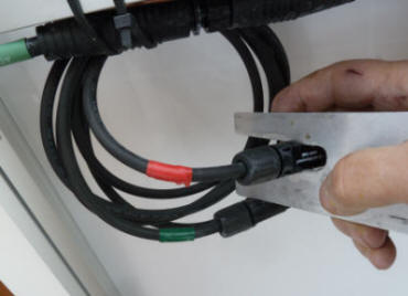
- Disconnected the positive lead on the first PV module
and the negative lead on the 2nd PV module from their micro-inverters, and
connected them to each other.
Repeated this for the 2nd panel positive to 3rd panel negative leads.
- Disconnected the positive lead on the 3rd panel from
its micro-inverter. Checked the voltage of the first string with a volt
meter. There was enough light leaking through the tarp to verify that the
polarity of the string was correct and the voltage was reasonable.
Connected the negative lead from the first panel to the charge controller
negative cable for string 1.
Connected the positive lead from the 3rd panel to the charge controller positive
cable for string 1.
This completed the rewiring for the first string.
- Repeated the steps above for the 2nd string.
The little homemade tool in the picture to the right
pushes in the little gadgets that release the connector -- this saves on the
finger nails and makes the connections faster. All of my array is done
with MC4 type connectors.
5 - Opened the battery circuit breaker on Elec-Trak.
Hooked up the battery pack to the charge controller by plugging in the in the
big grey 3 prong plug. This is where the old external charger plugs into
the Elec-Trak pack. For this test, there was an open in this circuit
somewhere, and rather than spend time finding it, I made temporary connections
with the yellow and green wires in the picture to hook the charge controller to
the battery pack.
The charge controller is compatible with a 36 volt pack, and charges the full
pack as a series string of six 6 volt batteries.
6- Uncovered the PV panels.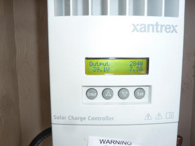
Closed the battery circuit breaker in the Elec-Track (this hooks the charge
controller to the battery pack, and the charge controller starts to come up).
Closed the PV disconnect (this connects the PV modules to the charge
controller).
7 - Went through the little Q and A with the charge controller on its LCD
panel. Just answered a couple questions about battery type, etc.
8 - As soon as the dialog was completed with the charge controller, it
started charging the battery pack at about 280 watts. The wattage
was low because it was cloudy.
9 - Simulated house loads on the Elec-Trak charger/inverter by hooking up a
1200 watt space heater to the inverter 120VAC outlet.
Ran this for about half an hour. Nothing unusual -- the charge controller
continued to charge.
-----------
Shut Down:
10 - Covered the PV modules with tarp.
11- Open the PV disconnect.
Charge controller shows "Charger off -- low light" message.
12- Open the battery circuit breaker.
Charge controller turns off (goes dead).
13 - Redid all the MC4 PV module connections to their original connections
with the micro-inverters.
14 - Uncover PV panels.
15 - Once all the wiring was back to normal, closed the AC disconnect at the
house.
The Enphase micro-inverters came back up to normal after a few minutes -- PV
system operating in normal grid-tied mode after a few minutes.
The writeup makes this seem more involved than it is -- it took less than
half an hour for the first time hookup to go from grid-tied to off-grid
emergency power.
So, this is one way to make the Elec-Trak and the PV array serve double duty
as a power supply for the house during long power outages. It looks like
it will work out well in that it did not involve investing much money, and it
provides enough power to keep the essential stuff running.
If you have ideas on alternative ways of accomplishing the same thing, I'd
like to hear what they are??
Gary
December 13, 2011