Search
The Renewable Energy site for Do-It-Yourselfers
ProMaster DIY Camper Van Conversion -- Electrical and Solar
|
Our aim for the camper van electrical system is to be able to do without electrical hookups indefinitely, and to be able to be away from any power source for a day or two without much sun and without having to run the engine.
To achieve this we have tried to keep electrical loads down by choosing efficient gadgets, avoided some high power consumption electrical devices, included some extra battery capacity, and a large solar panel to charge the battery when sun is available.
This section goes over the design of the electrical system for the camper conversion, the selection of components, and the installation.
Back to the ProMaster camper van conversion main page...
|
|
| |
Important Update
The material on these pages describing our camper van conversion has been moved to our new new site dedicated to efficient RVs and camper vans.
The new site covers all the material here and adds a lot of new material on other camper van conversions, camper van design and build, resources for people converting vans, other efficient camping vehicles, new ideas in efficient RVs and camper van travel hints.
The new site is here...
I'm leaving these pages here as you may have bookmarked them and the Comments section has some good suggestions, but I suggest that you go to the new site -- I won't be updating this material anymore.
Thanks to all the people who read these pages and especially to the people who left comments and suggestions! Feedback on the new site is very much appreciated.
Gary
|
|
Table of Contents
| |
Safety Warning and Disclaimer
There are serious safety
issues involved with wiring your own system. The voltages are
high, and potentially lethal. Doing the system incorrectly can lead to serious consequences down the road.
PV systems have the added
hazard that even when the grid power is turned off, the system can be
"live" and present a serious shock hazard.
If you don't feel like you
want to put
in the time to learn how to do this correctly, then find an electrician
that you can partner with to do this part.
I want to make it very clear
that I am not an electrician, and I take no responsibility whatever for
the correctness of the wiring hints below -- you need to do your own
homework!
http://www.builditsolar.com/Contact/legal.htm
|
Overview
We do not want to be tied to electrical hookups at RV parks, so we incorporated a good sized house battery and tried to minimize our electrical loads. Most of our loads are DC and run directly off the house battery with only a couple of modest AC loads that can be powered either by our onboard inverter or shore power.
The house battery can be charged from the van alternator, or from a large solar panel on the roof, or from shore power if available. The battery can supply a couple of days (or more) with typical loads, and on a sunny day, the solar panel can recharge the battery fully.
Note that at this stage, most of the component installs and wiring have been completed and tested to some degree, but there are still a few things to do, and a road trip to see if it all works well together in actual use.
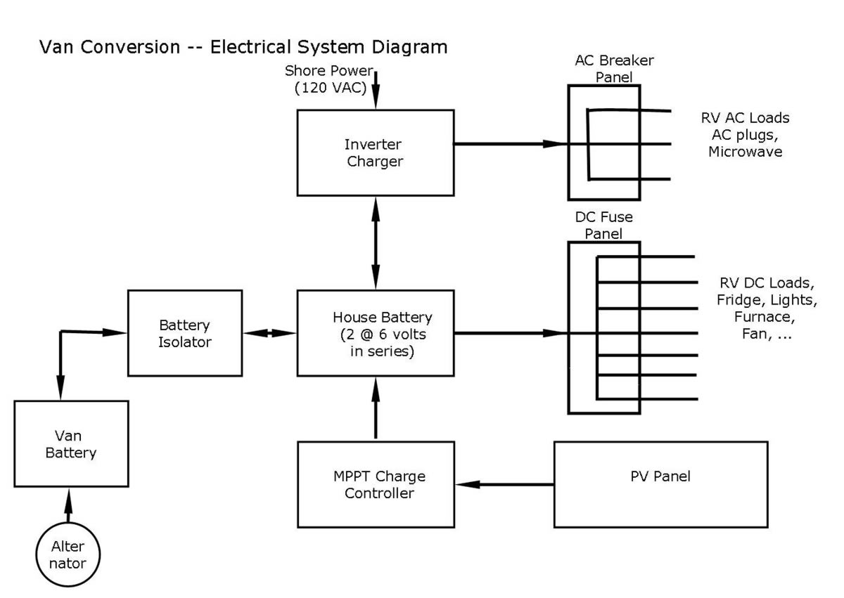
At the heart of the camper electrical system is the house battery. It can receive charge from three separate sources: 1) the van alternator when the engine is running, 2) the roof mounted solar panel, and 3) the inverter/charger when plugged in to shore power.
The house battery powers all of the DC loads (like lights, fridge, furnace fan, water pump) via the DC distribution panel. It also powers an inverter to provide 120 Volt AC house power to our small number of AC loads. Most of the electrical devices on the van run directly from the 12 volt house battery.
The Battery Isolator prevents the RV loads from running down the van starting battery, the PV panel charges the house battery via the Charge Controller, the DC and AC distribution panel safely distributes power to the RV electrical loads, the Inverter/Charger supplies 120 AC power from the house battery and also charges the house battery when hooked up to shore power.
All of this explained in much more detail below.
Components:
These are our choices for the main components.
Batteries
We used two 200 amp-hr, 6 volt golf cart batteries from Costco connected in series for 12 volts. This gives us some reserve for cloudy days..
We thought about using an AGM battery, the advantages of the AGM battery is that it does not need water to be added (low maintenance), it vents less hydrogen during charging than a flooded battery, and no chance of spillage.. On the down side, they are quite a bit more expensive for the same capacity, and appear (from the Trojan Battery data below) to have a shorter life.
The conventional flooded lead-acid golf cart batteries we used are less expensive and very readily available, but will require checking the water levels from time to time, and the battery compartment will have to be vented to the outside to prevent hydrogen buildup. But, flooded batteries vent very little hydrogen when charged at the correct rate.
Just as an approximate comparison -- some data on two of Trojan Batteries offerings of flooded and AGM batteries.
| Type |
Model |
Voltage |
amp-hr(20hr) |
Length |
Width |
Height |
weight |
Cycles
(80% discharge) |
Cost/bat |
|
| Flooded |
T-105 |
6 |
225 |
10.3 |
7.11 |
11.07 |
62 |
750 |
$110 |
|
| AGM |
6V-AGM |
6 |
200 |
10.3 |
7.08 |
10.74 |
65 |
500 |
$295 |
|
| |
|
|
|
|
|
|
|
|
|
|
Trojan recommends a charge rate of 10 to 13% of the 20 hr amp-hr rating, so about 22 to 30 amps for our golf cart batteries -- lower charge rates are OK, but higher charge rates will result in more gassing and shorter life. They also recommend 3 stage chargers. Charging voltages for flooded and AGM batteries are different, so the charger should be settable to the type of battery you have.
Both types will have a longer life if they are not discharged as deeply, but, it seems like for a camper van that might only be used 30(?) times a year that discharging to 80% should still give a very long battery life. Designing for 80% discharge allows the use of a smaller, lighter, more compact, and cheaper battery compared to (say) designing to 50% discharge.
The batteries will live inside the van in a case that is vented to the outside.
Another option that is just becoming practical is to use Lithium batteries (as used in electric cars). They would reduce weight and size by quite a bit over the lead acid batteries, but are still expensive, and would likely take some careful homework to get right.
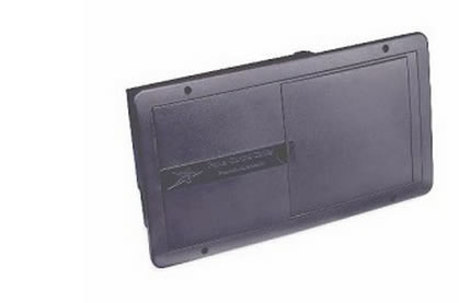
AC and DC Distribution and Fuse Panel
After quite a bit of looking around, I found this nice and not very expensive distribution panel for RV's that handles both the AC and DC distribution in one fairly compact package.
It provides for up to 12 DC circuits and up to 4 AC circuits.
Battery Isolator
This gadget allows the van alternator to be used to charge the house battery, while preventing the van starting battery from being drained by powering loads in the RV. It isolates the van starting battery from the house battery when the ignition switch is off so that RV loads only discharge the house battery. The idea is that even if you discharge the house battery overnight, the van starting battery will still be fully charged.
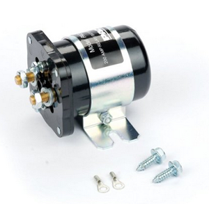
This relay based unit appeals to me because: 1) it does not have the voltage drop that the diode based isolators do, 2) it does not get wired between the alternator and the starting battery as the diode ones do (so less interference with the van wiring), and 3) It is easy to hook up because it just needs a wire from the starting battery and an 12V source that goes on with the ignition switch.
Not sure if I'm reading this right, but it seems like when you start the van that this unit puts the starter battery in parallel with the house battery. I guess this could be good if your starting battery is low, but maybe not so good if your house battery is low?
In hindsight, a unit with a lower amperage rating would have been fine. The unit is inline with a 50 amp circuit breaker, so anything over 50 amps would probably be fine. The maximum recommended charging current for the golf cart batteries is about 30 amps.
Another option would be to use a Voltage Sensing Relay. This is a relay similar to the one above, but the relay is activated just monitoring the van battery voltage to determine if the engine is running or not. It requires less wiring.
Inverter/Charger:
The inverter/charger performs two jobs. When you are not hooked up to shore power and are being powered by the house battery, it provides limited 120 volt AC power for the van from the house battery. When you are hooked up to shore power, it turns off the inverter function and passes the shore power through to the AC loads that are connected to the inverter, AND it charges the house battery using a full 3 stage charger.
We selected the Tripp Lite APS1250, which provides 1250 watts of AC from the battery, and when in charger mode, provides up to 30 amps of battery charging using a 3 stage charger.
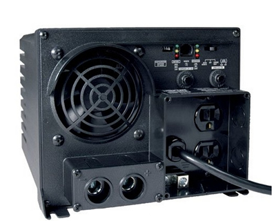
These inverter chargers are made by several companies. I chose the Tripp Lite mostly because I have a larger one I bought several years ago and it has held up well.
I like this kind of inverter/charger because: 1) it eliminates the need for a separate battery charger to charge from shore power, 2) it has 3 stage charging, so its easy on the battery, 3) it automatically switches from the inverter powering AC loads to the shore power when you plug into shore power, so you can hook your AC loads up to the inverter and they will be powered whether you are on shore power or on house battery power.
Like most of these inverters, it draws some power from the battery whenever the inverter is turned on even if nothing is plugged into the inverter, but it can easily be turned off manually when no AC power is being used, so this is a nuisance, but not a serious one.
Solar Charge Controller:
The charge controller goes between the PV panel and the house battery. It transforms the PV panel output voltage down to a voltage that is suitable for charging the battery, and it prevents the solar panel from overcharging and damaging the battery.
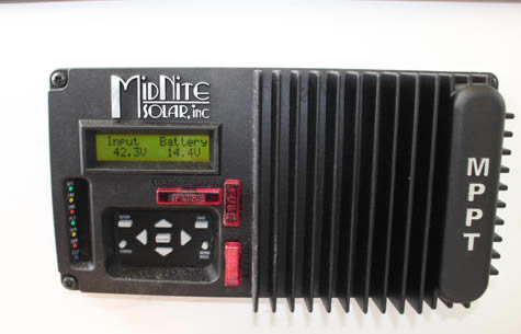
I am using the MinNite Solar KID charge controller. This is a relatively new design that has quite a bit of flexibility for small solar systems. It includes MPPT (Maximum Power Point Tracking) which is more efficient than the PWM models.
The unit is very nicely made in the US. The manual is written in an informative and down to earth style that is refreshing compared to the awful manuals that come with so many products. I'm told the phone tech support is very good.
The unit includes basic monitoring of the system, and they sell an add on unit for more extensive monitoring if desired.
Midnite Solar has a nice online tool that lets you see if the PV panel(s) you are planning to use are compatible with the KID.
Price is about $285.
Update: March 4, 2015: They have just raised the price up to $440. I think that this is kind of steep, and I'd probably look for a better option.
PV Panel:
I decided to use just one large solar panel. This seems easier than mounting and wiring together several panels.
The panel I selected the SW315 from Solar World. Its a 315 watt, 72 cell panel. The 72 cell design provides enough voltage (36 volts) to work with the KID charge controller as a single panel.
I ordered the panel from the local Platt Electric -- their price was competitive and if you pick it up at Platt there is no shipping charge. With a little discount they gave, it came to $368 -- about $1.17 per peak watt.
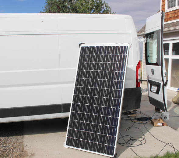
I have not mounted the panel yet. Thinking about mounting it as low as possible and aft of the Maxx Fan on the centerline of the roof.
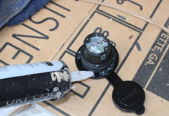
Still thinking about the best way to bring the two wires from the PV panel into the van. I'm wondering if I can bring them through the backup camera housing?
Wire:
For most of the DC and AC circuits, I used regular 14 gage Romex house wire. I used nearly all of one 250 coil. There are a couple runs that use 12 gage Romex due to higher demand and/or to reduce voltage drop. I'm aware that some sources recommend using stranded wire for greater vibration resistance, but the Romex is widely used in RV's and does not appear to cause an problems. The outer plastic protective sheathing and its wide availability at low cost are pluses.
There were a few places where larger gage stranded THHN wire was used (e.g. between inverter and battery and between van and house battery). I got this all at Lowes where they will cut pieces to the length you want.
For the most part, I used this ampacity table to determine the maximum capacity of a given wire gage, and this voltage drop table (the 12 volt section) to determine the minimum wire gage for less than 2% voltage drop.
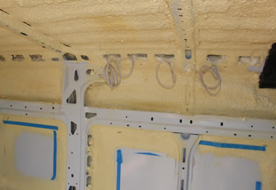
Did all the wire runs now while its still easy to run the wires. |
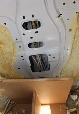
This is the new wire runs going up the cavity in the main frame. The PM provides lots of place to run wires through the frame and longerons.
I used flexible plastic conduit over the Romex in a few tight places. |
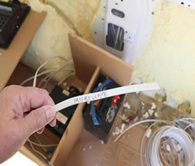
Be sure to mark each end of each wire run.
|
Circuits
While the overall wiring diagram gets a bit busy (and more than I am up to drawing), it really consists of a few simple functions that are largely independent of each other. This section goes through the details of each of the functions, which are:
- House battery charging from the van alternator
- House battery charging from the solar panel
- Satisfying 12 volt DC loads (DC distribution panel)
- Satisfying 120 volt AC loads and Shore Power
House Battery Charging from Van Alternator
This is the electrical subsystem responsible for charging the house battery from the van alternator when the van is running.
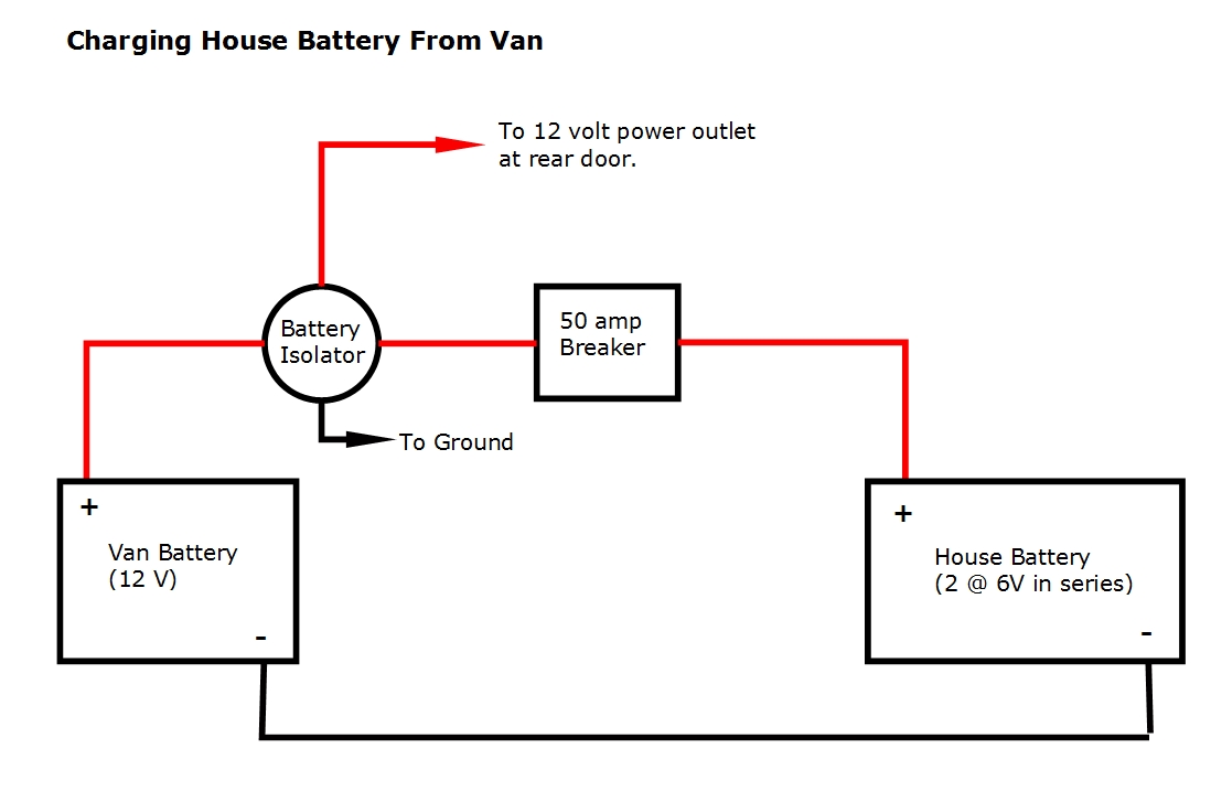
When the van engine is running, the relay closes allowing the van battery/alternator to charge the house battery.
The battery isolator relay connects the van battery to the house battery only when the van ignition switch is on. This prevents house loads from discharging the the van battery and resulting in a vehicle that has a flat battery in the morning and won't start.
The barratry isolator relay is turned on by connecting it to a 12 volt power source on the van that is only on when the ignition switch is on. I used power from the 12VDC outlet near the driver side back door as it is only powered when the ignition is on. I ran a 14 gage wire from the 12 VDC power socket to the battery isolator. The other relay terminal on the battery isolator is hooked to any handy ground. The isolator I used is a PAC-200 (see above) -- the 200 amp rating is quite a bit more than is required.
The 50 amp DC circuit breaker protects the wire between the van and house batteries. The circuit breaker can also be manually switched off, so it acts as a disconnect when you want to be sure there is no connection between the van and house batteries.
The van alternator is the source of power for both charging the van battery and the house battery.
For the two golf cart batteries, charging current is not supposed to exceed 30 amps. I do not know what the charging current will turn out to be for the ProMaster, but I plan to measure it, and if more than 30 amps, take steps to reduce it.
The wires between the house and van battery are 8 gage -- this provides the 50 ampacity with less than 2% voltage drop for the about 10 ft run.
| |
Note
The diagram above shows a breaker which protects the wiring between the two batteries from over current that originates from the House Battery, but the wiring between the two batteries is not protected from over current originating from the van battery. For example, if the wire connecting the van and house batteries were to develop a short to ground, the circuit breaker near the house battery would break, but there is no fuse or breaker in the wire from the van battery. So, a fuse should be added near the van battery in the wire that connects the two batteries. This could be the type of fuse that connects to one of the ban battery plus terminals with a lug on the other end of the fuse that the wire to the house battery connects to.
I plan to add this fuse to my setup shortly. |
Battery Charging from Solar Panel
This is the part of the electrical system that charges the house battery using a roof mounted PV panel.
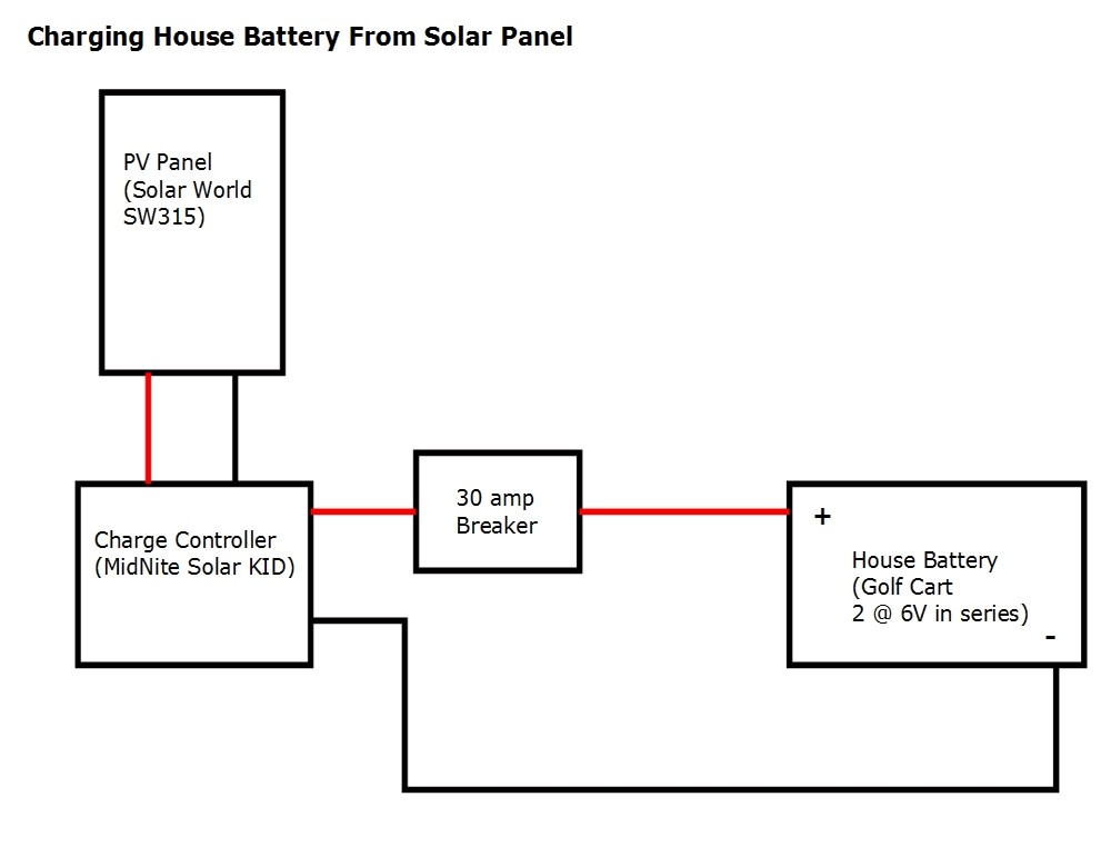
The solar panel is a large one from Solar World that provides 315 watts under full sun. It is a 72 cell PV panel so, it has a higher output voltage (36 volts) that is compatible with the input voltage range of the Midnight Solar charge controller with only the one panel hooked up.
The charge controller is from Midnight Solar -- its is described under the Components section. Basically, it transforms the DC voltage put out by the solar panel to the voltage needed to charge the house battery (so the PV panel might be putting out 36 volts and the charge controller transforms this to 13 to 14ish volts needed to charge the battery. The charge controller can be set for charging either AGM or flooded batteries. Its a 3 stage battery charger. The charge controller also prevents the PV panel from overcharging the house battery, which would damage it.
The 30 amp DC breaker between the charge controller and the house battery is what Midnight Solar recommends as this is the maximum charge current that the charge controller can supply. It also protects the #10 wire. Right now this breaker is a model that does not have a manual shut off switch built into it, and I plan to replace it with one that does when I find one.
The PV panel provides standard MC4 PV panel connections (a positive and negative). To connect this to the charge controller, I bought a 50 ft long MC4 extension cable and cut it in half. I used one half of it to connect to the plus MC4 terminal on the PV panel and the other half to connect to the negative. The extension cord is #10 wire, and will probably end up being about 15 ft long. The maximum power point current for the PV panel is 8.7 amps. The voltage drop for 15 ft of #10 wire at 8 amps is about 2%, or about 0.7 volts under full sun conditions -- this seems OK to me.
The wires connecting the charge controller and the house battery are #10, which has the required 30 amp ampacity. The wire run is only a couple feet long, so the voltage drop is low.
Satisfying 12 Volt DC Loads
This is the part of the electrical system responsible to safely supplying power to the campers 12 volt load:
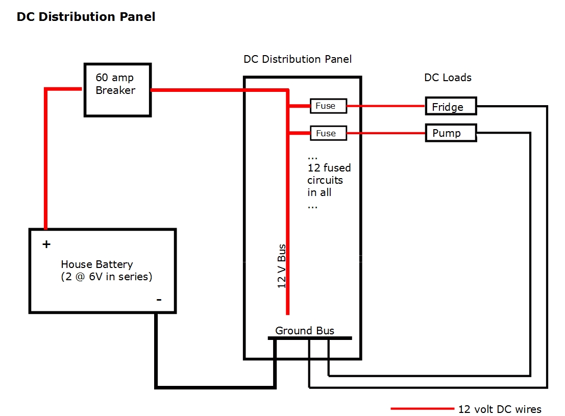
The DC distribution panel takes 12 volt power from the house battery and distributes it to the various 12 volt loads in the camper. It provides individual fuse protection for each 12 volt circuit.
I am currently using 11 of the 12 available fuse positions.
The 60 amp breaker in the line from the house battery to the DC panel is somewhat more than I think our total DC usage will ever be, and is well within the 100 amp maximum rating of the DC panel.
Note that for our system, the DC and AC distribution panels share the same housing, but are separated by an internal partition.
Satisfying 120 Volt AC Loads and Shore Power Battery Charging
This part of the electrical system is responsible for distributing power to the 120 VAC loads in the camper, and also manages whether the source of the AC power is shore power or the camper inverter. It also covers charging the house battery from shore power.
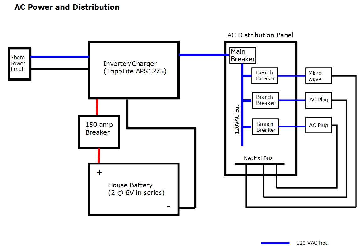
The AC panel distributes power to the 120 volt AC loads in the camper in the same way as the DC panel (above) distributes power to the DC loads. We have planned the camper to minimize AC loads and only have a couple of AC outlets and a circuit to power a small microwave.
The inverter/charger plays the key role in how the AC power is supplied. If the camper is not hooked up to a 120 VAC shore power connection, then the inverter/charger goes into inverter mode, and takes power from the house battery and transforms it to 120 VAC. It will supply up to 1250 watts in this mode. If the camper is hooked up to shore power, then the inverter/charger shuts down its inverter, and just passes the shore power through itself and to the AC distribution panel. It also starts up its battery charger and if the house battery needs charging, it charges it from the shore power -- it supplies up to 30 amps of charge current.
For the wires from the inverter/charger to the house battery Tripp Lite recommends #2 AWG for this model as long as the length is 16 ft or less (ours is only about 3 ft). It says to use a fuse in this line that is located close to the battery and rated at least to the maximum amperage listed on the inverter, which is 127 amps. I am using a 150 amp breaker, which seems high for #2 wire which has an ampacity of 115 amps -- will check further into this.
Since our AC loads are low, the shore power receptacle is just a 20 amp regular 120VAC plug. I think this will be fine and it allows us to just use a regular 12 gage extension cord to hook up to the shore power tower. To hook up the shore power receptacle, I just cut the plug off the end of the inverter/charger power cord and wired it to the shore power receptacle.
Installation
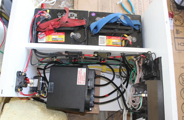
This section provides some pictures showing how I installed the components in our van.
The batteries plus all the main components take up an about 2 by 2 ft space under the bed on the drivers side.
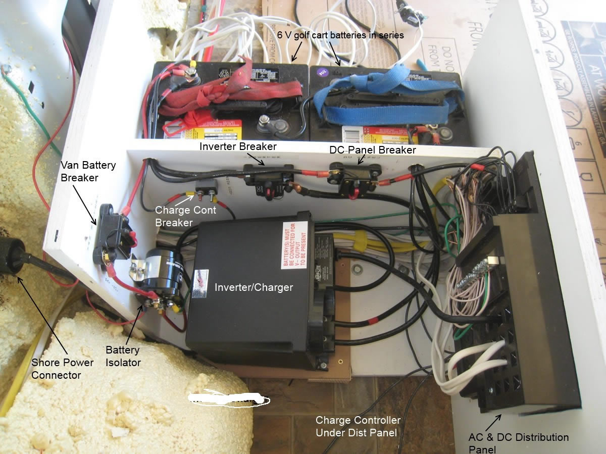
The breakers can also be used as switches to disconnect each function.
The distribution panel on the right serves as both the DC and AC distribution panel -- AC on forward end and DC on aft end.
The battery case still needs an end and top and will be vented to the outside.
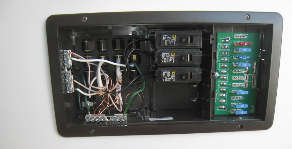
Distribution Panel
This pictures shows the AC and DC distribution panel (top) and the solar charge controller (below). They are mounted on driver side bed enclosure facing the aisle between the two beds.
This shows the AC/DC distribution panel with the cover off. The DC distribution panel is to the right (with the car type DC fuses), and the AC distribution panel to the left with the AC circuit breakers.
The DC panel provides for up to 12 DC branch circuits, of which I am using 11 (some of the fuses have not been installed yet).
The main breaker is the top one (it shuts off all AC). Up to 4 branch circuit breakers can be installed below the main breaker (I'm only using 2). Note that the 30 amp main breaker is going to be replace with a 20 amp later.
Switch Panel
I just recently added a small panel that adds on/off switches to the furnace and to the pump, and provides some extras for future use. It also provides 12 volt DC and USB charging outlets as well as a small volt meter to provide for easily monitoring the house battery voltage.
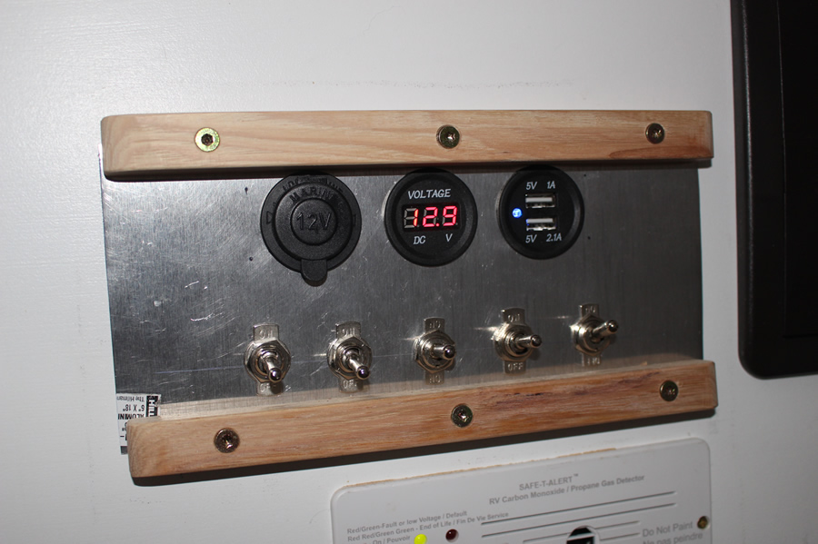
The switch panel mounts next to the fuse panel on the vertical face of the driver side bed platform.
The two switches on the left are pump and furnace, and the remaining switches are spares for future use. We have always found it to be a good idea to turn the pump off when not in the RV, as any kind of leak or faucet left on will cause the pump to run and drain the tank and them damage the pump. The switch on the furnace allows you to completely turn the furnace off and still have other DC gadgets powered up.
The top row has a 12VDC outlet, then volt meter, then a dual USB outlet.
The blocks of wood on the top and bottom are to keep things from hitting the switches and accidentally tripping them.
I have not updated the wiring diagram to show this panel, but the switches are in the plus lead between the fuse and the the furnace or pump, and the switches should be rated to at least the same current as the fuses.
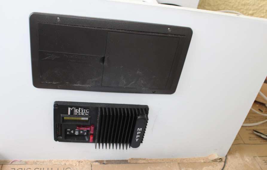
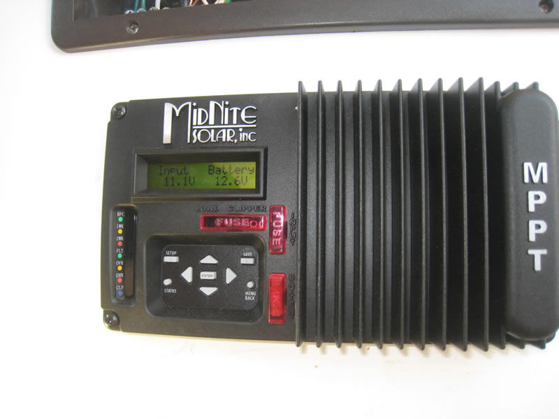
Solar Charge Controller
The charge controller goes between the PV panel and the house battery and regulates and optimizes the charging of the battery. It also prevents the PV panel from overcharging the battery.
The MidNite Solar KID charge controller is mounted in the bed enclosure just below the distribution panel. This means you have to get down on hands and knees to read the status, but it does keep the wire runs short and the electrical bay compact. If we decide to do upper cabinets (above the windows) in the van, I may move the charge controller to one of the upper cabinets for easier reading -- I'd convert the hole for the current position into an air vent to ventilate the electronics area.
There are several status screens that display various info about the solar charging -- e.g. PV panel voltage, battery voltage, PV panel watts, ...
Shore Power
Since our AC loads for the camper are small, I decided to just use a 15/20 amp shore power connection -- this is just a regular 12 gage extension cord that plugs into an ordinary 120 VAC outlet. Most RV's now use 30 amp or 50 amp shore power connections, but with our small AC loads we just don't need that.
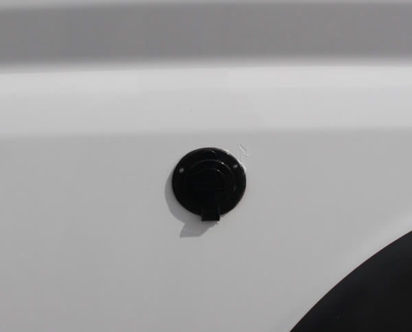
This is the through wall connection we used:
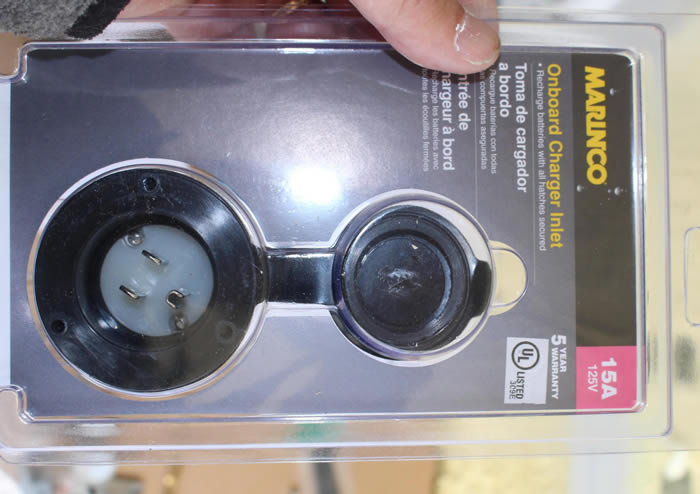
A bargain by RV part price standards at only $15.
These pictures show installing the shore power receptacle.
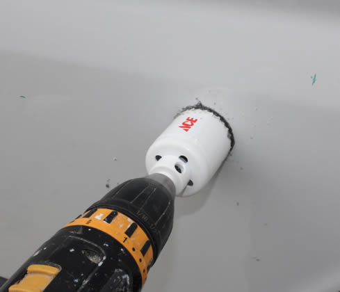
Using hole saw to drill 1 7/8 hole through van sidwall.
|
I used a little silicone caulk between receptacle and van side wall
|

Wiring the shore power receptacle
|

Rubber boot on shore power receptacle.
|
From the outside -- open and closed.
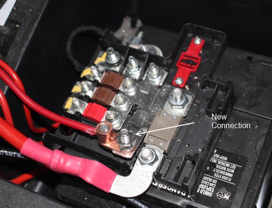
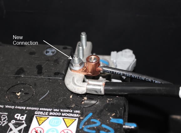
Connection to Van Battery
The connections to the van battery are shown below. I just used some unused connection points on the ProMaster battery terminal lug.
Left picture is the positive terminal connection, and right is the negative terminal connection.
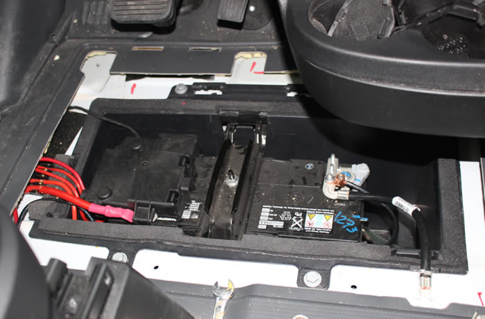
Van battery with new connections and terminal cover in place.
Securing Heavy Components
The batteries weigh about 60 lbs each and the Inverter/Charger is also heavy. I was concerned about these breaking away in a crash and coming forward to injure passenger or driver. So, this end of the bed box is bolted down through the floor with five 3/8 inch steel bolts. The other end of this bed houses the propane bottle and is bolted through the floor with several more bolts. The bed boxes are made out of a premium quality MDO plywood with all joints glued and screwed.
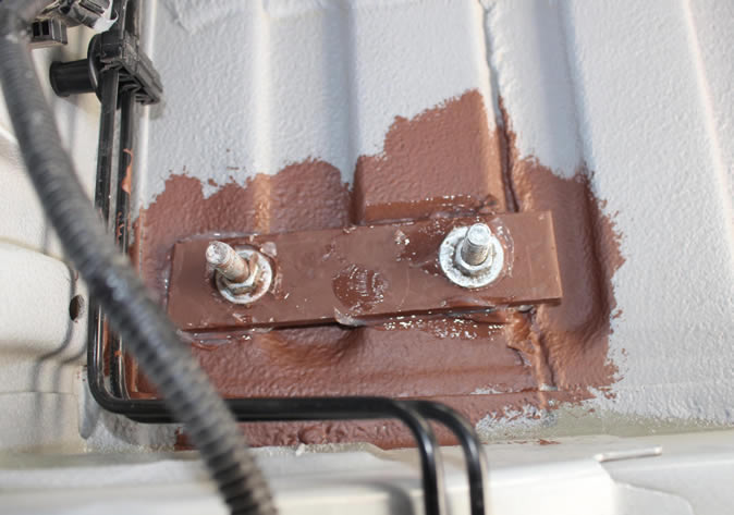
The picture shows how the through floor bolts are anchored under the floor -- the steel plate provides tear out resistance. The brown paint is Rust Oleum rust primer.
Still to do to complete the electrical install
- Complete the enclosure of the batteries and vent to the outside.
- Install all of the load end devices such as fridge, furnace, lights, Maxx fan, ...
- Test it all on a road trip
Electrical Loads Estimate
I did a rough estimate of the power use while in camping mode, and estimated the battery size and PV panel size needed to support this load for a couple days.
I have assumed an 80% battery discharge level in these estimates. I know that batteries will last longer if only discharged to 50%, or even less, but if you look at the Trojan estimate for number of charge/discharge cycles for an 80% discharge, its about 750 cycles. For an RV that only gets used maybe 30 days a year, 750 cycles is about 25 years, and I'm sure the battery will die of something else before 25 years. Maybe I'm missing something?
The spreadsheet also includes a rough heat loss calculation to get the furnace size and the power drain for the furnace fan and electronics. This came out to about 3000 BTU/hr with 32F outside and 68F inside the van -- this is for an insulated small van.
If you have something that will view Excel Spreadsheets, download Excel Spreadsheet here...
Otherwise, table below is copied out of the spreadsheet, but its hard to read because of the formatting.
| Van Conversion -- Electrical loads Estimate |
|
|
|
|
|
|
|
|
|
|
|
|
|
|
| These are loads for one 24 hr period. |
|
|
|
|
|
|
|
|
|
|
|
|
|
|
|
|
|
|
|
|
|
|
|
|
|
|
|
|
|
|
| Available Power From Battery |
|
|
|
|
|
|
|
|
|
|
|
|
|
|
|
Battery size (amp-hr at 12V) |
discharge depth |
voltage |
Energy avail (wh) |
|
|
|
|
|
|
|
|
|
|
|
100 |
0.8 |
12 |
960 |
Trojan SCS150 RV/Marine battery: 100 ah, 11.3 L X 6.7 W X 9.8 D |
|
|
|
|
|
200 |
0.8 |
2 @ 6
|
1920 |
This could be two of the Trojan 6V golf cart bats (or two Costco golf cart bats). |
|
|
|
| Might want to just leave space provisions for the 2nd battery. |
|
|
|
|
|
|
|
|
|
|
|
|
|
|
|
|
|
|
|
|
|
|
|
|
|
|
|
|
|
|
|
|
|
|
|
|
|
|
|
|
|
|
|
|
|
| Assumed below that things that are on all the time (CO detector, fridge) will run off the battery for 16 hours -- that engine running or solar will take care of the rest) |
|
|
|
|
|
|
|
|
|
|
|
|
|
|
|
|
|
|
|
|
|
|
|
|
|
|
|
|
|
|
|
|
|
|
|
|
| Solar Panel: |
|
|
|
|
|
|
|
|
|
|
|
|
|
|
|
| Based on the stuff below, you would want the solar panels to put in about 500 wh over the day. |
|
|
|
|
|
|
| |
|
|
|
|
|
|
|
|
|
|
|
|
|
|
|
|
|
|
|
|
|
|
|
|
|
|
|
|
|
|
|
|
|
|
|
|
|
|
|
|
|
|
|
|
|
|
|
|
|
|
|
|
|
|
|
|
|
|
|
|
|
|
|
|
|
|
|
|
|
|
| Electrical Loads: |
|
|
|
|
|
|
|
|
|
|
|
|
|
|
|
| Item |
Usage |
Time (min) |
Wattage |
Energy (wh) |
|
|
|
|
|
|
|
|
|
|
|
| Lights |
three LED at 3.5 watts each? |
180 |
10 |
30.0 |
|
|
|
|
|
|
|
|
|
|
|
| water pump |
|
6 |
40 |
4.0 |
|
|
|
|
|
|
|
|
|
|
|
| TV |
|
60 |
20 |
20.0 |
|
|
|
|
|
|
|
|
|
|
|
| Hair Dryer |
|
4 |
500 |
33.3 |
|
|
|
|
|
|
|
|
|
|
|
| Furnace fan |
|
210 |
22 |
77.0 |
This is based on 14 hours per day when heating is needed at 25% load factor (see below) with 12K furnace, or 210 min |
| computer |
|
90 |
40 |
60.0 |
|
|
|
|
|
|
|
|
|
|
|
| Fantastic fan |
|
30 |
21 |
10.5 |
low 1.3 amp, hi 1.75 amp (note that this would be much higher for summer, but furnace would be lower) |
| CO detector |
|
960 |
1 |
16.0 |
the 1 watt is just a guess -- should find out |
|
|
|
|
|
|
| LP gas detector |
|
960 |
1 |
16.0 |
the 1 watt is just a guess -- should find out |
|
|
|
|
|
|
| Fridge |
THIS ONE NEEDS REFINEMENT |
960 |
12 |
192.0 |
This is roughly based on Jeff Yago's article times about 3X -- still seems kind of low. |
|
|
|
|
|
|
0.0 |
|
|
|
|
|
|
|
|
|
|
|
| Total |
|
|
|
458.8 |
watt-hrs per day |
|
|
|
|
|
|
|
|
|
|
|
|
|
|
|
|
|
|
|
|
|
|
|
|
|
| Optional added loads |
|
|
|
|
|
|
|
|
|
|
|
|
|
|
|
| microwave |
minimal use if not on shore power |
0.12 |
700 |
84.0 |
|
|
|
|
|
|
|
|
|
|
|
|
|
|
|
|
|
|
|
|
|
|
|
|
|
|
|
| Notes: |
|
|
|
|
|
|
|
|
|
|
|
|
|
|
|
| Fridge: |
|
|
|
|
|
|
|
|
|
|
|
|
|
|
|
| * with this setup, and 80% discharge, the 12 V - 100 AH would be good for about 2 days, and the 2 6V 225 AH would be good for about 4 days (both probably less in the real world) |
|
|
|
| * JY says that good fridges use 2 to 3 ah/day per cf -- conservatively use 4 ah/day-cf. |
|
|
|
|
|
|
|
|
|
|
|
|
|
A 1.7 cf fridge then uses (4ah/day-cf)(1.7 cf) = 6.8 ah/day, or (6.8 ah/day)(12 volts) = 82 wh/day, with an average draw of 3.5 watts (seems low) |
|
|
|
|
|
Dometic says 40 watts, but this would be 365 KWH per year, which seems high for a tiny RV fridge. |
|
|
|
|
|
|
|
|
|
Need a better source for power used by the Danfoss compressor fridges. |
|
|
|
|
|
|
|
|
|
|
|
| * At 0 F outside temperature, the furnace would be on twice as much and furnace watt hours would be 150 ish. |
|
|
|
|
|
|
|
|
|
|
http://www.rvfurnace.info/ |
|
|
|
|
|
|
|
|
|
|
|
|
|
|
| * In summer, more fan operation might add as much as 200 or so wh, but furnace would drop to 0 (-62 wh) |
|
|
|
|
|
|
|
|
|
|
| * adding a microwave even if operated on battery would not be too awful as long as time of use is limited. |
|
|
|
|
|
|
|
|
|
|
|
|
|
|
|
|
|
|
|
|
|
|
|
|
|
|
|
|
|
|
|
|
|
|
|
|
|
|
|
|
|
|
| Van heat loss : |
|
|
|
|
|
|
|
|
|
|
|
|
|
|
|
| Item |
area |
R value |
Tavg outside |
Tin |
Heat loss (BTU/hr) |
|
|
|
|
|
|
|
|
|
| walls |
210 |
6 |
32 |
68 |
1260 |
|
|
|
|
|
|
|
|
|
|
| Floor |
78 |
9 |
32 |
68 |
312 |
|
|
|
|
|
|
|
|
|
|
| ceiling |
72 |
6 |
32 |
68 |
432 |
|
|
|
|
|
|
|
|
|
|
| windows single |
30 |
1.5 |
32 |
68 |
720 |
|
|
|
|
|
|
|
|
|
|
| windows double |
18 |
3 |
32 |
68 |
216 |
|
|
|
|
|
|
|
|
|
|
| infiltration |
468 |
|
32 |
68 |
82 |
|
at 3.0 ach |
|
|
|
|
|
|
|
|
|
|
|
|
|
|
|
|
|
|
|
|
|
|
|
| Total Heat Loss |
|
|
|
|
3022 |
BTU/hr |
|
|
|
|
|
|
|
|
|
|
|
|
|
|
|
|
|
|
|
|
|
|
|
|
|
| So, a 12K BTU/hr furnace would be running (3022/12000= 25% of the time) |
|
|
|
|
|
|
|
|
|
|
|
|
|
|
|
|
|
|
|
|
|
|
|
|
|
|
|
|
|
| Propane burn per day would be (3000 BTU/hr)(24 hrs)/(92000 BTU/gal) (0.8 efic) = 0.97 gal/day |
|
|
|
|
|
|
|
|
|
|
|
Correction: The power drain for the 700 watt (nominal) microwave should be more like 1000 watts.
Solar Panel Charging:
Using PVWatts as a rough way to estimate output...
For a 315 watt panel mounted horizontally in Billings MT, the average output per day is:
1575 watt-hrs per day in July
440 watt-hrs per day in October
300 watt-hrs per day in December
With tilt equal to latitude (46 deg), the July number goes to 1450 wh/day and the Dec output goes to 800 wh/day.
This is with average weather for Billings -- you can, of course, have full overcast days with very little production.
Our estimated use per day is about 400 watt-hrs, so for most of the year, on average, a 315 watt panel would easily meet our daily needs even with the horizontal tilt. For the deep winter, the panel only meets about 75% of our daily usage, but if it could be tilted, it would meet our daily needs with a bit of margin.
The above are with a PVWatts service factor of 0.77 -- the real world one may be a bit less than this with the battery charge/discharge inefficiency included.
Note that PVWatts has a bug that results in inaccurate output with arrays smaller than 1 KWH, so you have to put in a larger array, and then just scale the output numbers down.
Weights, Costs, Labor
I did not keep track of the time spent installing the electrical system as it was spread out over a month. It was probably roughly the equivalent of 3 full days.
I'd be happy to hear any ideas, suggestions, corrections, or questinons -- use the Comments link just above.
Gary
September 18, 2014