Search
The Renewable Energy site for Do-It-Yourselfers
DIY Differential
Controller
|
Gordy designed and built a microprocessor based differential controller to control the pump on his solar water heating system.
The material below provides a full description of the design, notes on what drove the design, issues to keep in mind if you use or alter the design for your system, details on the hardware assembly, and full software listings for the controller software.
Thanks very much to Gordy for providing this detailed description!
|
|
Page Index
Design Notes
Differential Temperature Controller Using a Comfile Technology CB210
Build a Digital Controller for Your BuildItSolar $1k Solar Hot Water Heater!
20 February 2013
Basic Concept:
Conceptual Design:
The primary objective driving the design of this controller has been the desire to achieve reliability, low cost, and where possible, simplicity. A failure of less than an hour may well result in the rupture of piping in frozen collectors, or melt-down of collector assemblies due to excessive stagnation temperatures.
The Khanh master/slave variant of the BIS $1K solar heater was initially powered by a single Swiftech MCP655 pump. During initial testing an attempt was made to power the pump with three small, 15 watt PV panels. Web searches had suggested that powering with PV had various advantages – but the small panels were not sufficiently powerful. Thereafter, an ageing automobile battery became the primary electrical source for the pump, and the battery was charged by both the PV panels and various wall wart-chargers. Attempts were made to use the PV panels to additionally control the switching of the power to the pump, but early and late in the day the thermal water panels would be quite warm, but the PV power would be insufficient to reliably trigger the pump. It became obvious that a differential temperature controller was required.
A homemade, very simple comparator circuit had been in use for much of the initial two year period. It was based upon an LM324 op amp and has proven to be highly reliable – but, it involved a large number of trial and error modifications to get it there. Considering the differing situations faced by a variety of experimenters, it was decided to design a controller with better accuracy and improved flexibility. By using an assembled and tested micro-controller as the central core of the controller, the experimenter has the capability of readily modifying many aspects of the circuit through software.
Prior to completion of the solar storage tank, initial testing (15 Nov/ 2010) in direct sunshine suggested that the system would provide a respectable thermal energy harvest (slightly over 150 Btu/sq ft/hr) at a reasonable flow rate of about 1.8 gal (US) per minute.
Our case has proven to be a very difficult situation for implementing a solar domestic water heater. Numerous aspects are far from optimal, and, numerous aspects have been redesigned and modified to try to improve the situation. By far the biggest issue is lack of sunshine, sometimes several weeks would pass with no sun! Thus it seemed essential to make best use of any sunny opportunities – regardless of duration.
It seemed to be a 'no brainer' to add a secondary pump to grab any opportunity for more heat. Literature suggests that: (i) a second pump in series tends to improve lift capabilities (with little flow rate improvement), and (ii) a second pump in parallel improves flow rate (with little affect on lift). Head had not been an issue, but improving flow rate was critical. Thus this differential controller was initially designed and constructed to support activation of a second, parallel pump when the collector was sufficiently warmer than the tank to justify the extra pumping effort. Surprisingly, subsequent testing proved that a series pump configuration would provide a slightly better flow rate – but only about a 20% improvement.
Clearly, over the two year period, flow rates had degraded! Why, was a good question. Could this possibly be due to an increase in system pipe friction (as the exposed copper components had long lost their shiny new appearance)? Perhaps the new pumps were not as powerful as the original? Perhaps the flow meters were inaccurate or degrading performance?
In any event, the hardware aspects of the differential temperature controller enabled supporting either a series or parallel pumping strategy, and the programmable software could enable some optimization possibilities.
The Controller:
Comfile Technology manufactures the Cubloc product line of micro-controllers. The hardware capabilities within this product line range from rather basic to full featured, but all are programmed with the same, free, easy to use software development suite. The documentation is excellent – even for the novice! The Cubloc CB210 is a very simple micro-controller programmable in both the BASIC and ladder logic languages. The assembled and tested circuit board is a modest $30. The controller has 20 input/output port pins, six can be 10 bit analog to digital (A to D) converters, and three can be pulse width modulation (PWM) outputs. It can be powered with 9 to 12 volts dc in the 'EXT' configuration (actually 8v if it is regulated), or 5 volts from a PC's USB port.
Temperature Sensing:
Near the plumbing outlet of the solar collector is a 40k Ohm NTC thermistor (two actually, since one is still connected to it's $5 “Missil” indoor/outdoor thermometer for visual reading and confirmation). There are another pair of 40k Ohm thermistors (again one is still attached to it's indoor/outdoor thermometer) in the solar storage tank. A resistor is placed in series with each of the sensor thermistors (ie: the ones that have been cut off from thermometers), thus making two voltage divider circuits and a small known voltage is placed across the resistor circuits. As the resistance of the thermistors lowers as temperature rises, the voltage across each thermistor can be measured and converted to a temperature reading. The intact indoor/outdoor thermometers are used to assist in calibrating this conversion. In a nutshell, if the outdoor temperature is slightly greater than the water storage temperature, the controller turns on the water pump, if not, the pump is turned off.
Pump Control Interface:
The micro-controller is a very low power 5 volt device, and it is recommended that an interface circuit be used for driving the higher voltages and currents needed by most pumps. Various low power dc pumps such as computer server coolant pumps tend to operate at voltages around 12 to 14 volts at just a few amps. In such case, the interface could be either a bipolar transistor or the more efficient MOSFET directly driving either the pump or a relay.
Micro-processor circuits are very susceptible to voltage transients from switching power circuits. Higher powered pumps may require higher dc voltages and/or currents, or grid power (typically 115Vac). In such cases, the improved safety of the electrical isolation from a quality relay or an optically isolated, zero-crossing, solid state switch is recommended.
Design Detail:
The Controller Hardware:
Overall Design Philosophy:
One can be pretty certain that the proposed interface circuitry is far from an optimal commercial design. In all honesty, the driving criteria were (i) the parts had to be in my junk box, (ii) for replication by others, the parts had to be readily available (essentially generic), and (iii) the circuitry had to be robust (or at least easily tweaked) in the face of very differing operational situations.
A to D Considerations:
Two of the A to D inputs are used to sample the thermistor temperature sensors. The voltages on these inputs must never be less than minus 0.5 volt or more than 5.5 volts (assuming 5 volt power to the processor). Between the temperature sensors and the processor there are long wires that tend to act as antennae. One can expect them to pick up both 60 Hz ac hum and radio frequency noise that needs to be attenuated for both processor safety and measurement accuracy. In practice, one should try to constrain these A/D input voltages between zero and 5.0 volts. In the circuit, 2.2 micro-farad (low ESR) tantalum decoupling capacitors are used to filter out both the low frequency ac hum and high frequency noise. Under normal situations the use of these decoupling capacitors should be effective.
However, some situations could be excessively noisy due to near-by neon signage and/or heavy inductive equipment. In such situations, reverse biased, 5.6 volt zener diodes (as in 1N5339BT) are often used to limit voltage transients to safe levels at processor input ports. Note that as such zeners tend to introduce additional non-linearity to A to D thermistor measurements - they are best avoided unless absolutely necessary.
Note that the resistor dividers of each sensor are powered by more than 5 volts. To maximize the accuracy of the analog to digital conversion (there being only 1023 measurement intervals), it is recommended that as much as possible of the safe 5 volt input swing be used. The trick is to ensure that the values of the current limiting resistors and applied voltage are chosen such that the voltage to the A to D input is never outside the safe zero to 5 volt range - for all possible sensor temperatures.
When thermistors consume anything more than very minimal current, they self heat - thus providing erroneous temperature readings. Thus the 40k Ohm 'dollar store' thermometers have a significant advantage over the industry standard 10k Ohm thermistor. To reduce the self-heating effect even more, the thermometers tend to pulse the power to the thermistors only when being read. With a programmable controller, this too is easy. Simply use an output pin to energize an N MOSFET to switch the sensor power on momentarily (during readings).
Pump Interface Considerations:
When choosing a pump, one needs to ensure that it has the capability of providing the desired flow rate at the 'head' height involved. Additionally, the pump's operating temperature rating should be considered. Other considerations include preference to pumps with few moving parts, a long working life, and good performance versus electrical power input. Low voltage dc pumps have the advantage of ease of operation via a car battery - even if the grid power is down.
By nature, pumps are inductive loads. When the power to the pump is switched off, a reverse voltage is induced back into the switching circuit. It must be clipped or bled off to avoid damaging the switching circuitry! That is the reason for a reverse biased rectifier diode across both pumps and the coil winding of a relay. Note that in higher power situations, relay contacts can be prone to sticking – especially when switching dc loads. If using a relay, give preference to a relay of slightly higher contact rating than expected of the conditions.
Many newer dc pumps have semi-conductor speed controls built into the pump housings. In such cases, the preferred dc power supply is either a lead acid battery or high quality, regulated, switching supply (typical of lap top computers), or both. A 'cooler power adapter' is tempting as the current and voltage capabilities tend to be a good match for charging a lead-acid car battery in this application. However, the output voltage on some of these 'cooler adapters' can be very noisy with voltage transients. Should this be the case, a car battery should be additionally used in the circuit (to attenuate these transients).
Energizing the 115Vac input to a 'cooler adapter' (or another 115Vac to 13Vdc power source) only when the pump is operating effectively applies charge to the battery proportional to battery use. It prevents both the wasting of electrical energy and over-charging. This circuit provides for a relay in parallel with the main pump. The contacts of this relay can be used to switch the 'hot' side of the 115Vac line cord to the adapter (or other ac to dc power source).
In many ac power control situations, an optically isolated, zero-crossing, solid state relay may well be preferable to a mechanical relay. However, many do not tolerate the 'back EMF' of inductive loads well. As potential failure should be avoided, it is recommended that one carefully consult the data sheets. This would appear to be a perfect application for an optically isolated, zero-crossing, solid state switch. The author cautions that it might not be totally reliable depending upon the switching 'adapter' – as he has experienced occasional latching (both on and off) of the pump. This difficulty can arise because the ac input current to switching power supplies (ie: cooler adapters) tends to be high current pulses, which in turn generate 'back EMF” transients, and as a result, doesn't remotely resemble normal ac current into a 'resistive' load. When in doubt, a simple relay is probably a better choice for this application.
Power Supply Considerations:
The schematic identifies the use of a common 12v lead acid battery as the primary electrical source for the controller. Other power sources are possible within the range of 10 to 20 volts dc with the circuitry provided. This provides some flexibility for use of PV. In the 'ON” state, one can expect a voltage drop across the MOSFET pump switches of about a half volt. Thus one needs to ensure that the pumps can tolerate a voltage of the power supply voltage (say 13v) minus 0.5v (or the equivalent of 12.5v across the pump).
The Controller Software:
Overall Design Philosophy:
Throughout the design of the software (or more accurately 'firmware'), the intent has been to include the necessities, and include aspects sufficient for accommodating most potentially damaging situations - but otherwise, the intent has been to 'keep things simple'! A great deal of commentary has been included in the source code to facilitate modification to adapt to diverse situations.
The software is programmed in BASIC. No it's not elegant, but it is extremely easy to use. The editor provides online grammar hints, interactive debugging and a truly simple one click “>” keystroke to compile, download, burn and execute. Made a mistake? No problem, it can be reprogrammed about 10,000 times!
Measurement and Conversion of the Temperature Sensors:
Ideally one would like accurate measurement of temperature, however, all such sensors have some short-comings. NTC thermistors suffer from manufacturing tolerances, self heating effects, and are far from linear. Within a very confined temperature range one can often use a linear approximation, but the temperature range in this application is far too large. The source software attempts to circumvent the non-linearity issue by dividing up the operating temperature range into six intervals and implementing a different linear approximation for each interval. The equation used is the common Y=mX + b, where Y is the temperature, m is the slope, X is the A to D reading and b is the offset. The A to D reading intervals and six coefficients for both m and b are stored as constants in 'program' memory.
In the event one chooses to use differing thermistors, differing voltages and/or differing resistors in the voltage divider circuitry, an Excel type (actually Open Office 3) spreadsheet is provided to generate these coefficients. It is cautioned that while one can adjust the thermistor pulse voltage in the spreadsheet (presumably to ensure the input voltage to the A to D is within the 0 to 5.0 volts limits), one must remember to modify the 825 ohm resistor on the LM317 to actually adjust the pulse voltage in hardware!
Operational Flexibility:
The specification of the differential temperature set points can be easily redefined by the user. A small differential tends to increase heat harvest, but may introduce 'short cycling' of the pump, which in turn is 'hard' on the pump(s), and may well actually introduce cooling water into the solar storage tank.
The operational strategy for the solar system can be adjusted in numerous ways in software. For example, two separate power channels are provided (normally, one for each pump). If only one pump is to be used, the second channel could be used for controlling the timing of battery charging in some intelligent manner specific to one's situation. In addition, there are several unused ports available on the processor board just waiting for your innovation!
The Bottom Line:
Our solar water heating project faces numerous constraints and difficulties including the fact that we have:
- severe constraints regarding size, height, orientation and/or location of our collectors and solar storage tank,
- drainback gravity flow issues over a long distance from the collector to the storage tank,
- a relatively long distance between the storage tank and the post (DHWT) water heater,
- shading of the collectors early in the morning and late in the afternoon,
- a relatively cold climate, and
- poor quantities of direct sunshine.
Over the last two years we have attempted several modifications to overcome many of these issues. A forthcoming BIS article outlining these modifications (and our opinions as to their success) is planned for the near future. Notwithstanding the issues faced, we would like to assure everyone that we feel that our variant of the BIS $1k Solar Water Heater has been a success and a well worthwhile project. There are only a few days a year when it provides for all of our hot water needs. There are only a few days a year that it is incapable of providing any assistance. But, the rest of the year, it just chugs along pumping out most of our hot water needs – for an electricity cost of about a dollar a month. That's unbelievable value for less than a cup of coffee!
The BuildItSolar website has variants of the $1k Solar Water Heater appropriate for just about every possible site condition. We encourage everyone to give serious thought to building their own – and now they can even construct their own differential temperature control.
We would be very interested in comments or suggestions for improvement that anyone may have to offer.
Gord Scale, Adolphustown Schoolhouse
Pictures of the Differential Controller and Supporting Hardware
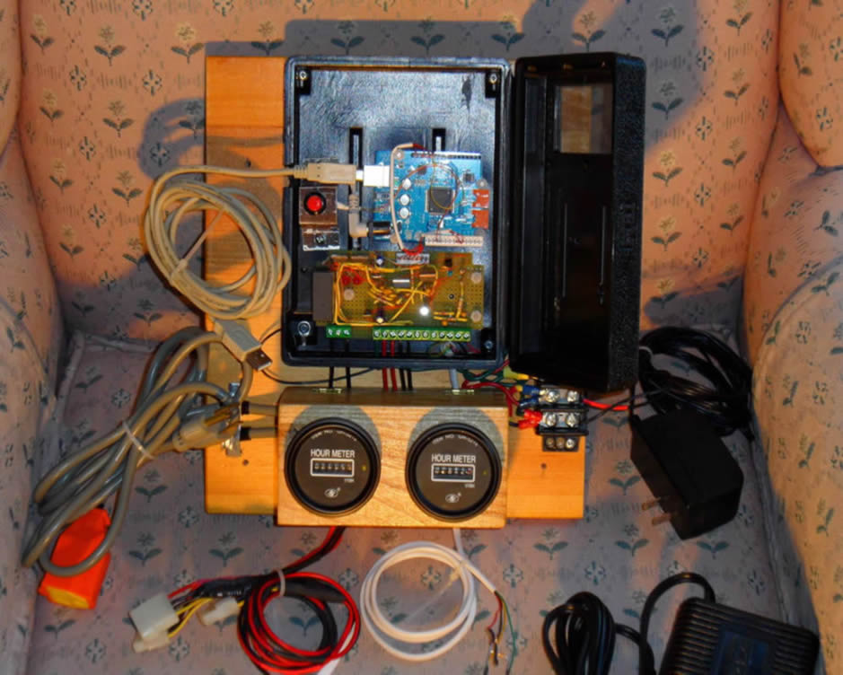
The completed differential controller, interface board, sensors, meters, and power supply ready to install
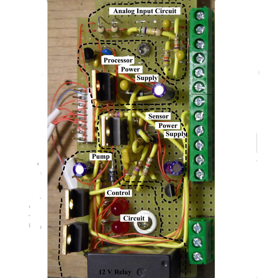
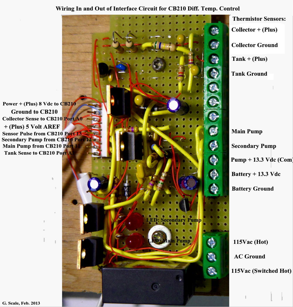
Pictures of the interface board (click for full size).
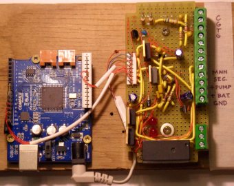
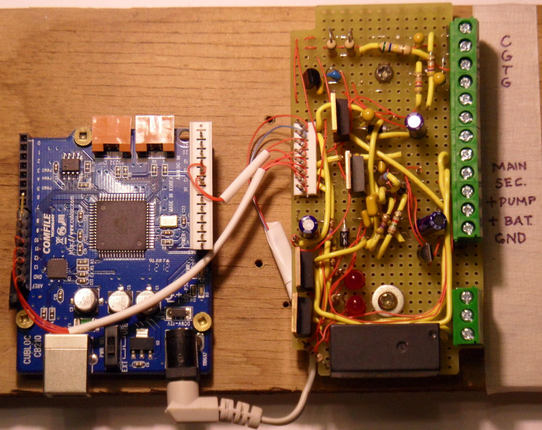
Bench testing the hardware
|
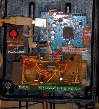
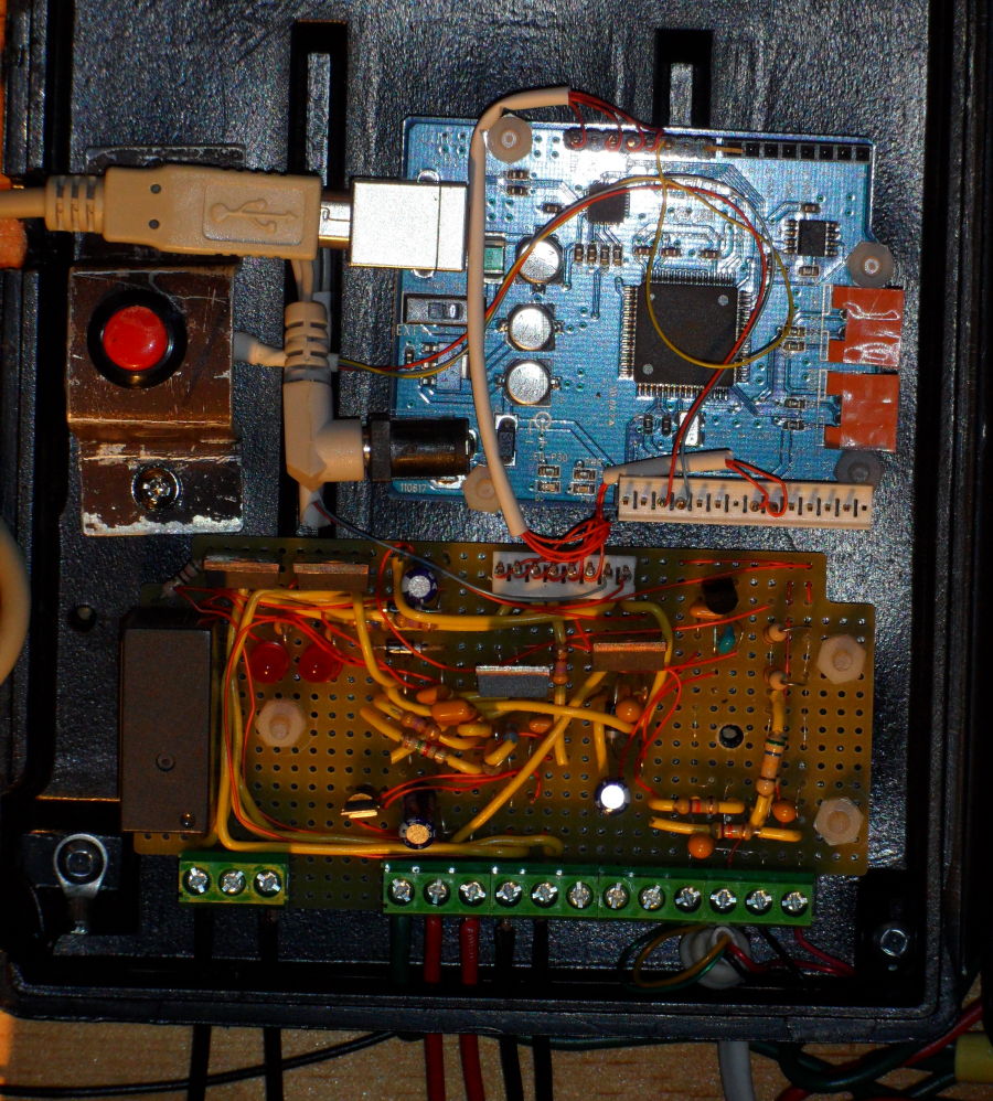
Differential controller in housing box.
|
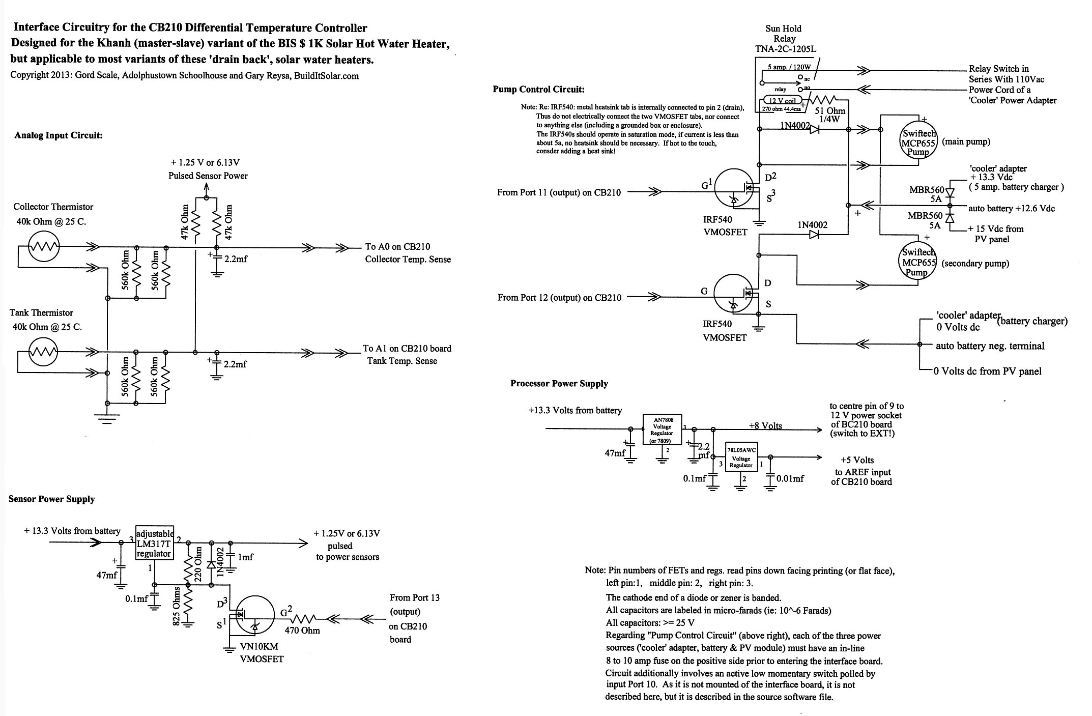
Interface Board Schematic

Click on the schematic for full size.
Software Source Files
To download the source files for this project and to learn about getting the free SUBLOC software development system ...
To just have a look at a copy of the source code as a web page...
Derivation of Software to Read Temperature Sensors
This spreadsheet shows the details on development of the software to convert thermistor voltage readings into temperatures.
Thermistor reading logic spreadsheet... (an Excel spreadsheet file)
Gordy
Gary June 2013