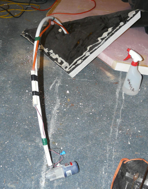
This is the small March pump that
is submerged in near the bottom of
the tank to pump water to
the collectors.
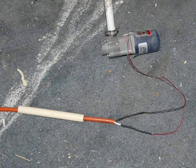
Wiring the pump with a waterproof
connection.

Close-up of the pump.
<< all this stuff below moved to Collector Construction page >>
Update November 11, 2008: Details on the new pump ...
A submersible pump is located near the bottom of the solar storage tank. Water from the tank is pumped by this pump up a line that goes through the lid of the tank. This line is T'ed off into two lines -- one line feeds the bottom of the left half of the collector, and the other line feeds the bottom of the right half of the collector.
Water returning from the two halves of the collector are joined into a single pipe at the collector, and this pipe runs down to drain back into the airspace above the water in the storage tank.
When the pump turns off, all of the water in the collector and collector plumbing drains back into the storage tank -- this provides freeze protection. No antifreeze is used.
I have used a solar PV panel to directly power a small submersible pump, and this also worked well. In this case, a thermal snap switch should be installed in the power line to the pump to shut if off when the tank temperature reaches 140F. The thermal snap switch could probably be installed between the EPDM lining and the first layer of insulation, and near the top of the tank.
With either type of pump, when the pump starts up, it must have sufficient pumping head capability to pump water from the water level in the tank up to the top of the collector. So, if the top of the collector is 8 vertical feet above the level of the water in the storage tank, the pump must have a startup head rating of at least 8 ft. Once flow is established, and all the pipes are filled, the required pumping head drops down to just the friction losses in the system.
The pump should be able to produce a flow through the collectors of around 0.04 to 0.05 gpm per sqft of collector area. So, for my 48 sqft collector, about 2 gpm is sufficient.
|
|
|
|
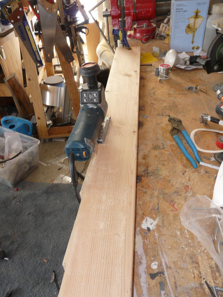
The picture shows the March pump I am currently using to pump water from the tank to the collectors. It is a March 893 12 VDC pump.
The pump is very light weight, and simply hangs from the PEX outlet line. The wire supplying the pump had to be spiced below the water level in the tank. To do this I soldered the wires together, than used heat shrink tubing, and finally I put a length of half in CPVC over the connection and filled it with silicone.
Since the controller provides a 120VAC outlet for the pump, I have a small 12 VDC power supply I plug into the controller -- the pump is then powered by the 12 VDC power supply. The power supply and pump together only draw 20 watts as measured with a Kill-A-Watt.
I'm still looking for the ideal pump and controller for this system. It seems like with the modest pumping requirement and modest temperature requirement, there should be a high quality low cost solution out there somewhere? Let me know if you have seen something that might work better.
Update November 11, 2008: Details on the new pump ...
If you are using one of the Grundfos or Taco HVAC circulation pumps, please note these installation cautions...

Picture shows plumbing connections between solar tank and the house water heater.
The tankless water heater that provides backup water heating when the solar heated water is not up to the needed temperature. The tank is on the right.
Basically, the cold water inlet to the tankless heater is brought over to the solar tank, and then back to the tankless heater. This way if the water in the solar tank is already hot enough, the tankless heater does not turn on at all.
I included valves that allow the solar tank to be cut out of the system, and the cold water routed directly to the tankless heater -- this way the solar tank can be worked on or drained without turning off the home water.
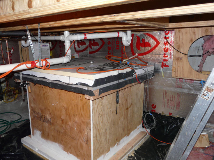
OK, its not pretty, but its very functional and durable --- who needs pretty in
the crawl space?
Gary September 21, 2008, October 10, 2009, April 23, 2010
| The collector absorber plate's job is to convert the incoming solar radiation
energy into heat and to transfer this heat into the water being circulated
through the collector.
For this absorber, fins made from 0.018 thick sheet aluminum which have been painted black are used to absorb the solar radiation and convert it to heat. The heat is transferred along the fin to the nearest copper riser pipe, and then into the circulating water. |
|
The fins I used for this collector were bought pre-formed from Tom Sullivan at the UP Truck Center in Upper Michigan. Tom worked out a good efficient tool for making fins when he was doing his own collectors, and decided to add the fins to the products he offers from his UP Truck Center. I believe that this is a good option, as the fins are made from the right thickness of aluminum, come with a very well formed groove, and are reasonably priced. But, making your own fins from locally obtained aluminum is also a good option. I made my own fins for all the collectors before this one, and can say that you can turn out good quality fins with simple tools. So, I'd have a look at both options -- price them out in dollars and your time, and see what comes out the best for you.
The fins for this collector are made from 0.018 thick aluminum, and the finished width (after forming the groove) is just over 6 inches. This is about the right combination of thickness and width. If the fins are made wider than 6 inches, then the fin thickness should be increase accordingly to allow for the greater heat flow to each riser pipe. Likewise, if the fins are made narrower, they can be made thinner without sacrificing efficiency.
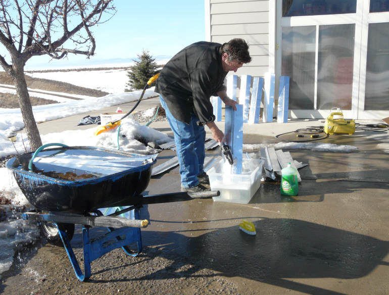
Clean the FinsThe fins come as bare aluminum, and have to be cleaned and then finished. The side of the fin that faces the sun gets black paint to absorb the solar radiation well. The back side that fits over the copper pipe gets a coat of corrosion resistant primer to provide part of the protection that prevents galvanic corrosion between the aluminum fin and the copper pipe. I washed the
fins in water with some detergent. Be sure to brush the inside of
the groove so that the primer will adhere well. If you make your own fins from aluminum soffit material (as I have on the collectors before this one), they come pre-painted and you can forgo the cleaning and priming step (below). If you use bare aluminum to make your fins, then you do want to do the cleaning and priming.
|
|
|
|
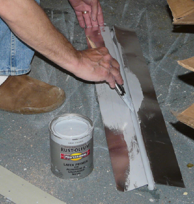
Prime the FinsI used this Rust-Oleum aluminum primer to prime the back side of the fins. Pay particular attention to getting the primer to coat the full inside surface of the grooves. A Zinc-Chromate primer would probably be an even better choice, but these have become more difficult to come by due to environmental controls. The primer I used was available at the local hardware. The combination of the primer plus the silicone discussed below serve to prevent the entry of water into the fin to copper tube joint area. This prevents any tendency for galvanic corrosion. Once the fins are all cleaned and primed on the back side, set them aside for later. |
 |
|
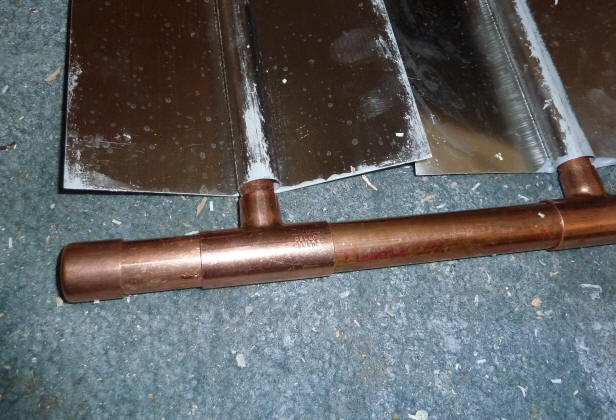
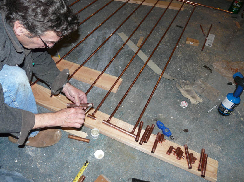
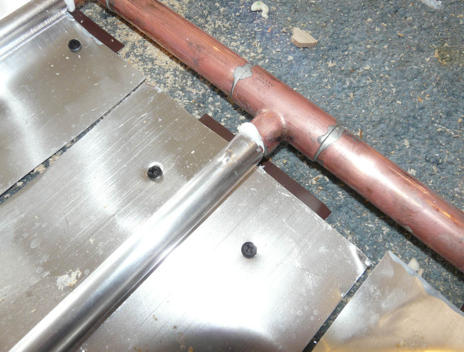
The copper pipe grid is made with half inch copper pipe soldered to 3/4 inch copper header (manifold) pipes. I used the regular Type M copper pipes intended for residential plumbing jobs. For the joint between the risers and the manifolds, I used reducing Tees. This is a nice straight forward way to make the connection, and requires only simple soldering skills. The reducing Tees can be quite expensive depending on where you buy them, but I found that PEXSupply.com has a nice price on them in quantities of 25. Be VERY careful to order the type with 3/4 inch on the straight through part, and 1/2 inch on the branch -- the pictures on the PEX Supply web page are make it easy to order the wrong ones -- I ended up calling them up to make sure, and was glad I did as I had picked the wrong version.
|
 This shows the manifold construction using reducing T's. |
First, establish the overall size of your collector. The things to bear in mind when setting the overall size:
The wall (or other) space you have available.
Allow for drain back slope: the bottom of the
collector must be high enough to allow for the collector supply pipe to
slope downward from the collector toward the storage tank at about
3/16thsinch per foot so that the collector drains back to the tank when the
pump shuts down.
Efficient use of materials is a consideration --
try to choose the size to avoid waste.
If the collector is wall mounted, and the roof
overhang is significant, you may want to stop the collector short of the
full height of the wall, as the overhang will shade the upper part of the
collector. More on this...
See the Sizing the System section for more on performance vs size of collector ...
All of the above will allow you to establish outside dimensions of your collector frame.
Now, establish the height and width available inside the collector frame by subtracting the thickness of the perimeter frame. The copper grid must then fit inside this space with some allowance for clearance and for the tilt of the copper grid for drain back. Layout a rectangle on the shop floor that is the size of the inside of your collector frame.
<< add sketch >>
Figure out where the supply line is going to come into the collector. This must be either the left or right lower corner. The lower manifold will be sloped down toward this corner so that the collector will drain fully when the pump is turned off.
The return line from the collector must then connect to the opposite upper corner (that is, if the supply comes into the lower right, the return must leave from the upper left).
Take the pipe you plan to use for the lower manifold, and place it in the proper position on your floor layout. This lower manifold must be sloped by about 3/16ths inch per foot of width for drainage. The lowest part of the manifold should clear the collector frame by about an inch -- this will be at the corner that the supply pipe comes in. If the manifold is (say) 12 ft long, then the supply end of the manifold will be about 1 inch above the lower collector frame board, and the far end of the lower manifold will be (12)*(3/16 Inch) + 1 inch = 3.25 inches above the inside of the frame. Allowing enough slope for good drain back of the water in the collector is critical for freeze protection in drain back collectors.
Now layout the top manifold in the same way. For our 12 ft wide example, the manifold will have about 1 inch clearance to the top frame on one end, and 3.25 inches clearance on the other end. It will be parallel to the bottom manifold so that all of the risers can be cut to exactly the same length.
Now lay in the left and right end riser pipes. They should be perpendicular to the manifolds, and approximately 3 inches in from the left and right frame edges. Note that because the manifolds are tilted with respect to the frame, the riser pipes will be tilted with respect to the frame sides. Now take a few of your fins, and lay them out left to right across the full width of the collector. The left most fin and right most fins should have their grooves centered over your left and right risers. If the spacing does not come out to an even number of fins, then you can move the end riser a little to make things come out even. If you end up moving the end risers out a bit to get an even number of fins to fit, then the two end fins can be trimmed with tin snips to fit in the available space. This does not have to be exact -- if there ends up being a slight overlap of the fins on each other, or a slight gap between fins, that's OK -- but, if its more than an 1/8 inch, I'd do some more fussing around.
Now that you have everything laid out to fit on the floor, measure the length of the risers, and the length of the short pieces of manifold pipe that will go between the reducing T's. Be sure to allow for the length provided by the fittings themselves. Its best to do a trail cut of a riser, and a couple of the manifold short pieces, and do a trial fit over your floor layout to make sure you have the lengths right.
The description above makes this all sound more complicated than it is. Just start laying it all out on the floor, and you will quickly see where its going. The most important thing is to make sure that the collector grid of pipes has down slope so that it will drain properly.
|
The supply line from the pump will come into the bottom manifold at one corner (the corner that the manifold pipe slopes down to). The return line from the collector leaves the top manifold of the collector at the opposite corner from where the supply comes in. This diagonal arrangement between the supply and return lines insures that the total flow path through each riser is the same, and that helps to make sure each riser gets the same amount of flow. There will be two corners that don't get either a supply or return line. For these corners, its best to use one of the reducing Tees and terminate the unused branch with a cap. If you use a reducing elbow to go from the 3/4 inch manifold directly to the half inch riser, that riser will get more flow than the others because it has less flow resistance. |
|
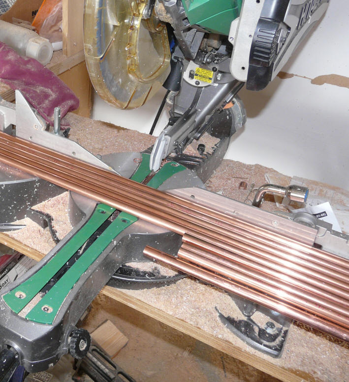
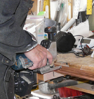
| Cut out all the risers for the
collector -- they will all be the same length. There are several ways to make all these cuts. If you have a regular wood working cutoff saw, I find that works fine for cutting all the risers at once. You can also use an electric saber saw, or one of the cutter wheel type copper pipe cutting tools that plumbers use. |
 |
|
 |
||
One thing to be careful of is don't count on the nominal 10 ft pipe lengths to be exactly 10 ft. The 10 ft pipe lengths I bought varied by as much as half an inch from each other. Basically this means that if you want a bunch of 9 ft lengths, its NOT safe to set up a stop to cut 1 ft off your 10 ft lengths!
Cut out the short pieces of the manifold pipes. I used my wood working cut off saw with a stop set to the right length to do the cutting -- this is fast and assures that all of the pieces will be the same length.
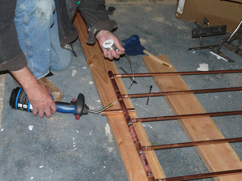
I think that I counted about 130 solder joints in the whole grid, so its important to have a good system both to speed up the work and to avoid leaky joints.
The most important thing is to clean and flux each joint carefully. If the joints are cleaned and fluxed well, the actual soldering is easy, and the likelihood of a leaker is small.
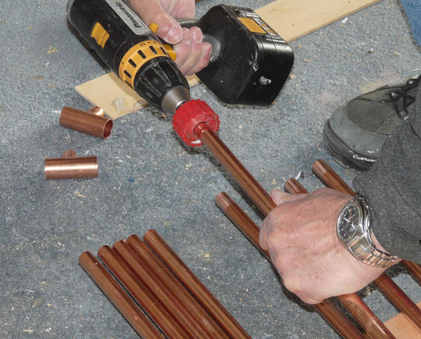
Clean all the fittingsClean all of the pipe ends and the T fittings carefully. I use the wire brush tools, but sand paper can also be used. There are lots of fittings to clean, so mounting the brush to the drill saves some time for the half inch pipes and fittings -- it was a bit too much torque for the 3/4 fittings. I would do all the pipes and fittings for one manifold, then solder that manifold, then move on to the other manifold. This way the fittings don't sit around a long time after cleaning.
|
  |
Flux all the JointsApply soldering flux to all of the cleaned fittings and pipe ends. Don't miss any!
|
 |
Solder the JointsNow push all the joints firmely together, and solder each joint. If you have not done any soldering before, not to worry. There are lots of good "how to solder" videos that are only a Google away. Practice on a scrap to get the feel. If you did the cleaning and fluxing carefully, you will probably end up with no leaking joints -- but, be sure to do the leak test below. After finishing the first manifold joints, repeat for the other manifold. |
|
You should have a copper grid that looks something like this:
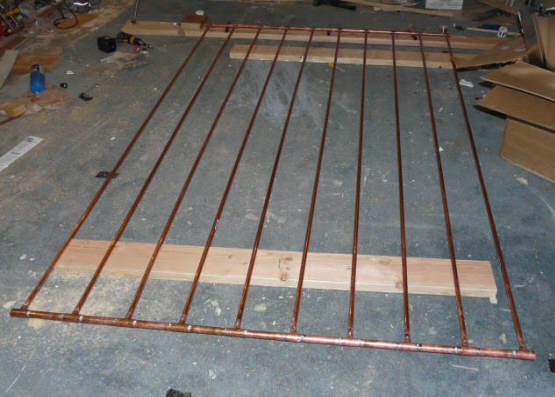
At this point, you want to test for leaks. Its tempting to skip this leak test, but don't -- its much easier to fix a leak now than after you have the grid mounted in the collector frame. To do this, I just plug the return line, then stand the collector up on its side with the supply connection up. I then use a funnel and a bucket of water to fill the whole grid with water -- be sure to get the air out. Then let it set for an hour or so and look for leaks and make sure the water level has not gone down. If you have an easy way to pressurize the collector for the leak test, so much the better.
From a performance point of view, this is probably the most important step in building the collector -- securing the fin to the riser tube in a way that will perform well thermally for 50 years.
Install Backing StripPlace a 3 inch wide strip of 0.018 thick aluminum under the riser
pipe where the next fin is to be installed. An alternative to using the backing strip...
|
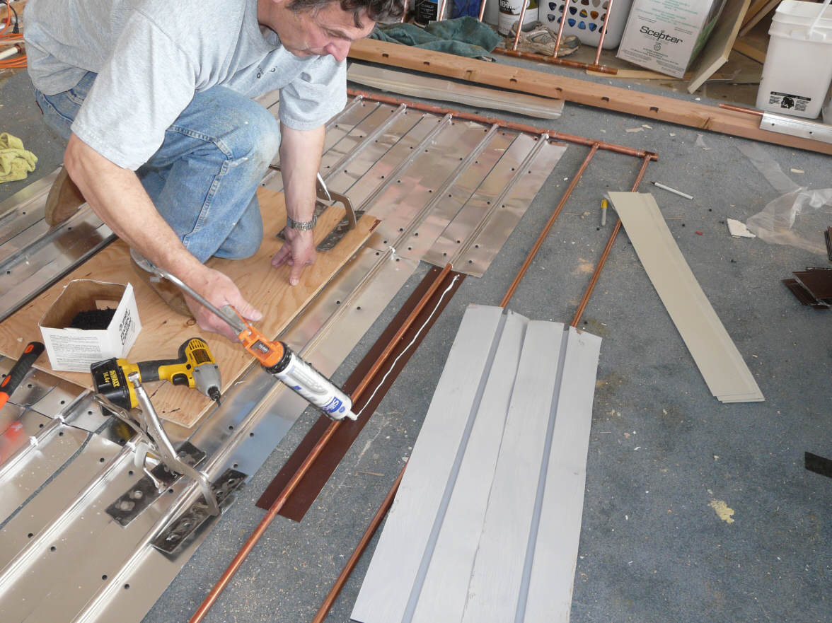 |
Silicone Caulk in Fin GrooveApply a small bead of silicone caulk in the fin groove. |
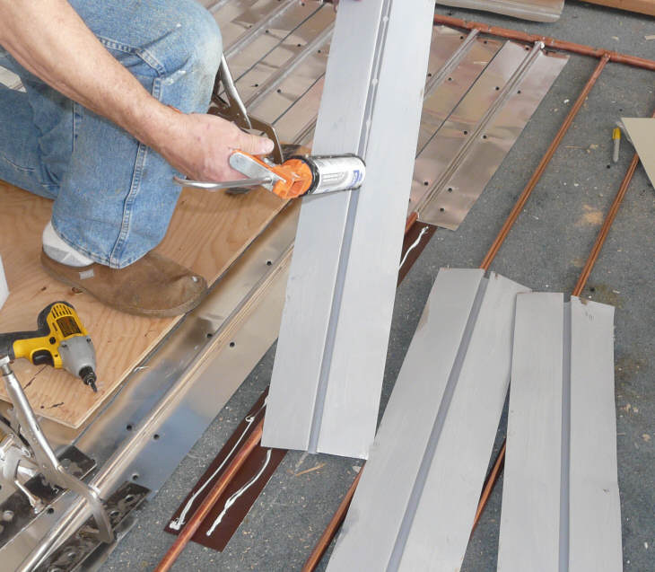 |
Press the Fin Onto the RiserPress the fin onto the riser pipe with the 3 inch flat strip under
the riser. |
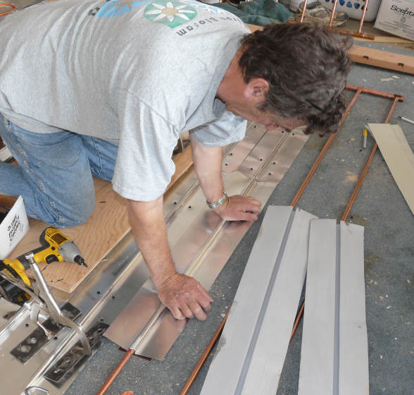 |
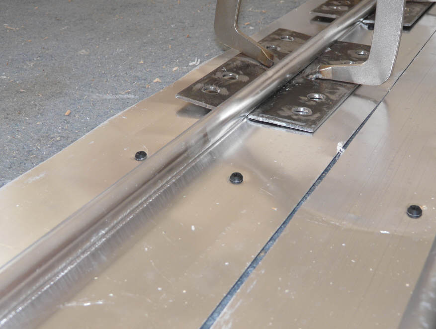
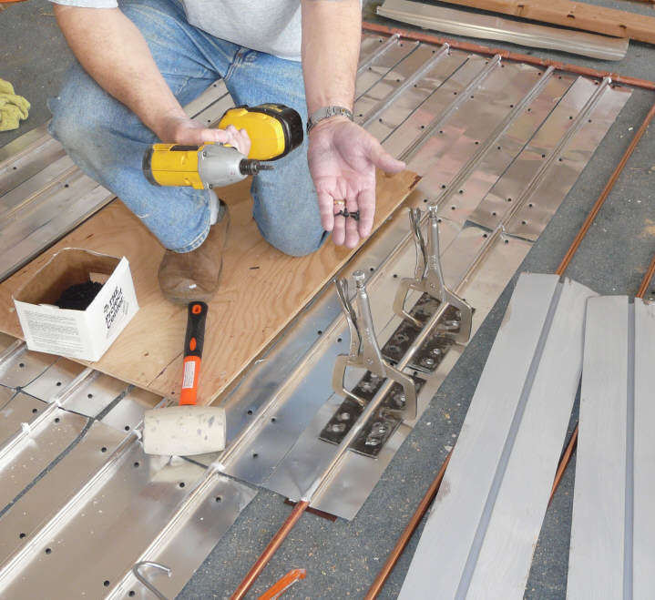
Clamp the Fin to the Riser PipeClamp the fin very tightly around the riser pipe. When you look at the fin from the end, you should see no gap between the fin and the riser pipe. The picture shows
Tom's modified vice grip clamps, which work very well. But,
you can make
simple clamps that will also do the job... But, either way its
very important to have a means to tightly clamp the fin to the riser
pipes. Once the fins are tightly clamped in place, use short sheet metal screws to secure the fins to the backing sheet. Use the screws in pairs directly across from each other as shown in the picture. The backing plate provided a tension tie across the bottom of the fin to keep it tightly camped in place. Some have suggested that pop rivets would work instead of the screws, and I'd guess that this is true. |
|
You should end up with an absorber grid that looks something like this.
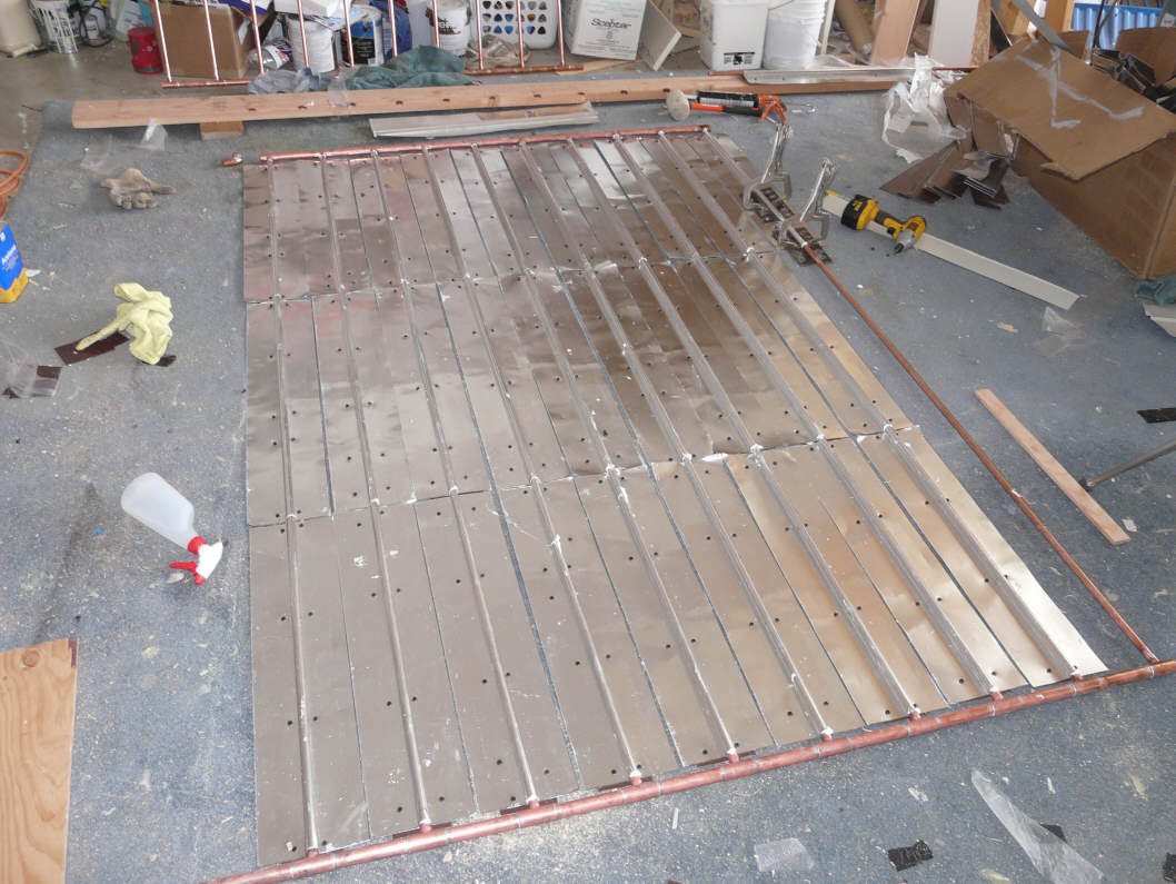 Nearly finished absorber grid. |
 showing the fin, riser, strip under riser and the screws that hold the fin to the flat strip. |
You can either paint it it black now, or wait until its installed in the collector frame.
I use the Rust Oleum high temperature barbeque paint in the flat finish.
After painting, its important to place the absorber plate in the sun and allow it to bake for a day before putting the glazing on -- this make sure that all the volatiles are baked out, and will not coat the back of your glazing.