Search
The Renewable Energy site for Do-It-Yourselfers
Reference Collector Construction
This page details the construction of the "Reference Collector". This
reference collector is run on every test alongside the collector that is
actually being tested -- it provides a standard level of performance for every
test. The reference collector is a traditional backpass collector in which
air is fan forced through the space behind the absorber sheet. Baffles are
used to insure that air scrubs the full surface of the absorber.
| |
Note that later in the testing both Scott and I
decided to change the reference collector from this backflow collector
to the collector that uses two
layers of window screen as the absorber. The screen collector
is simpler and cheaper to make, has a lower pressure drop, and performs
better than the backflow design on this page, so we think the screen
collector makes a better baseline.
Gary 5/15/2011 |
Back to the Solar Air Heating Collector test program
home...
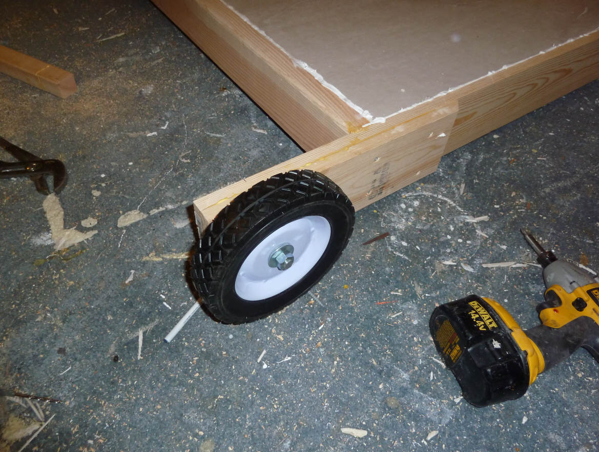
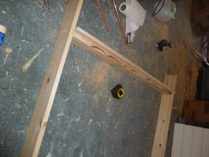
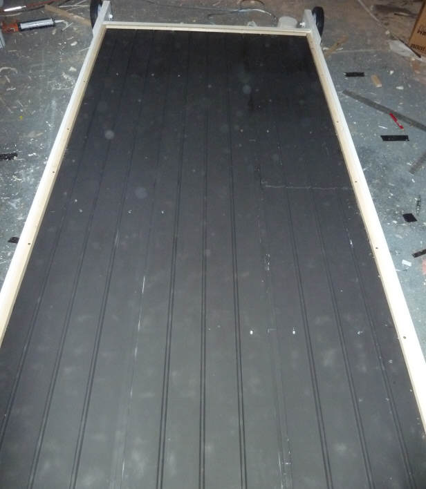
This is the basic collector box.
Sides are 1 by 4.5 (cut down from 1 by 6).
Top and bottom are 2 by 6 cut down to appropriate depth.
Bottom is a 2 inch thick sheet of polyiso.
There is no plywood back -- thought that the polyiso glued to the wood frame
with Great Stuff would be enough for a short life collector.
The sides extend past the top and bottom for wheels on the bottom and a handle
on the top -- so the collector can be moved around like a wheelbarrow -- tired
of trying to drag 100 lb collectors around :)
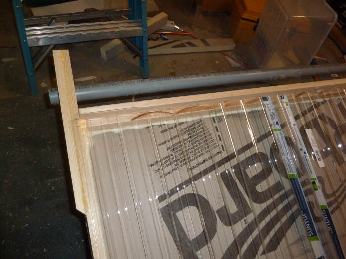
This is the top -- the Suntuf fits right over the sides, and the notch cut in
the top accepts the foam Suntuf wiggle strips.

Wheels on the bottom |
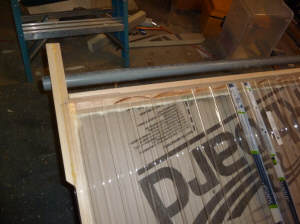
Handle on top. |
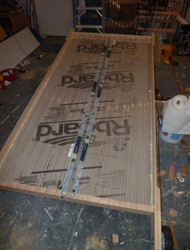
Just laying the Suntuf over the frame to see how it fits.
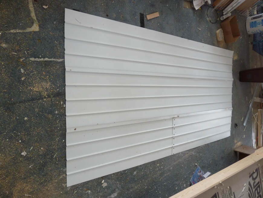
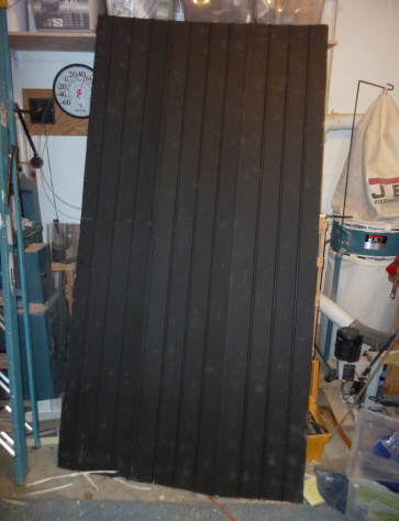
This is the alum soffit absorber.
It comes in 12 ft long strips that are 16 inches wide.
I took an 8 ft length out of each of the 12 footers, and then spliced the two
leftovers to make the third 8 ft strip -- very little waste for this size
collector.
The
This shows 2 of the 16 inch wide pieces going together.
I used a bead of silicone in the joint over the full length to provide air
sealing.
Plan is to have the brown side down and the white side (painted black) up --
this results in the big flat areas lying down on the edge strips and baffles.
This shows the 1 inch tall strips added all the way around the inside edge of
the collector box, and the four, 1 inch tall baffles.
This is all just glued together with Great Stuff.
The absorber will fit on top fo the 1 inch thick strips, leaving a 1 inch tall
air channel between the insulation board and the absorber.
Can't have too many clamps :)
I still need to cut the inlet and outlet holes.
The black painted absorber.
I had to trim off about 1 inch on each of the long sides -- I used the table
saw, but I think it would be easy with tin snips.

Box ready for absorber.
The top of the baffles are painted brown just to make them standout.
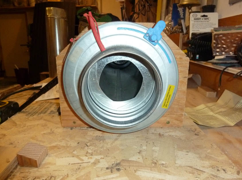
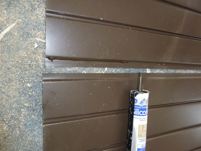
This shows where the supply (or return?) vent enters the collector.
This is a 6 inch to 5 inch transistion fitting pushed into a 5 inch hole drilled
in the 2 inch collector back insulation.
The plywood stiffens up the duct entry and also reinforces the corner of the
collector.
The 2 by 4 just prevents the duct fitting from being squished when the
collector is laid on its back.
Its sealed in with Great Stuff and then silicone caulked on the opposite
side.
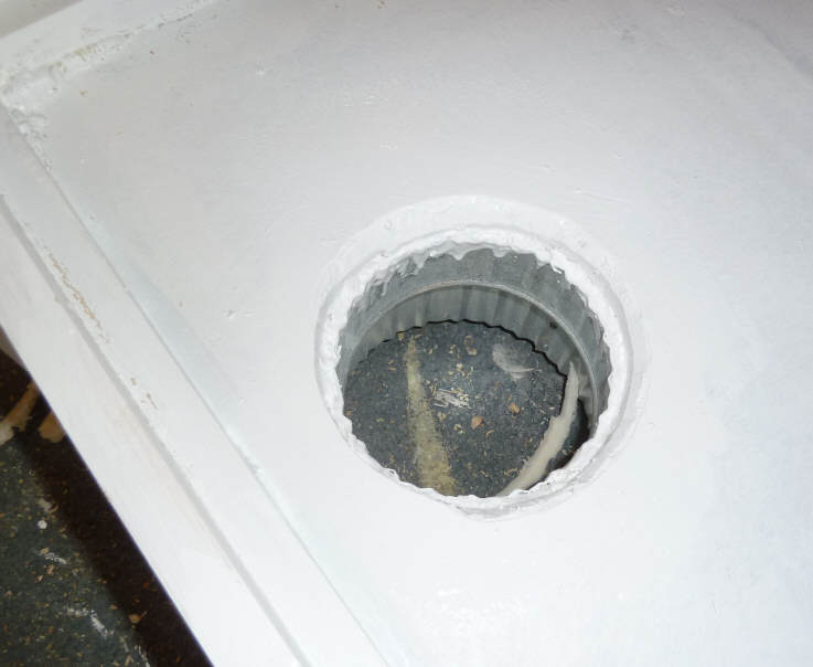
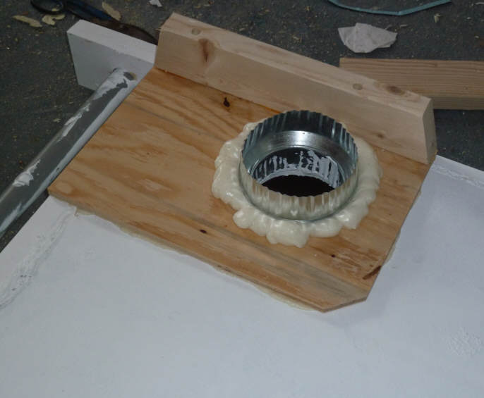
Close-up of the same fitting from the inside of the collector box.
This is the 5 inch diameter end of the transition fitting.
I tried to round the edges of the foam a bit to give a smoother flow into the
collector.
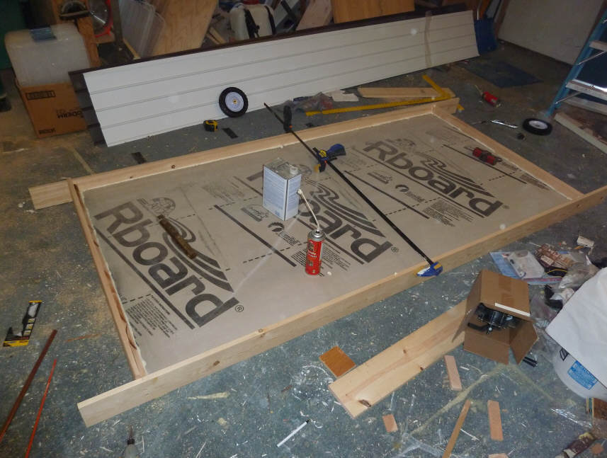
Installing Absorber

This shows the wood edge strips that clamp the absorber plate down to the wood
edge strips that support the plate underneath.
So, the screws pull the top wood strip down to the bottom wood strip with the
edge of the absorber clamped between.
Not sure if this is the best way, but its pretty easy, and does seem to be
relatively leak proof even without any gasket or sealer.
I wanted to be able to remove the absorber easily to be able to add/change
baffles, "turbulators", flow vanes, ...

This shows both the side and bottom absorber clamp down strips installed.
The bottom and top ones work less well then the side ones because of the
ridges in the soffit material.
I'll probably add some caulk or foam to the places between the ridges so they
don't leak air.
If no air leaks through from the bottom of the absorber into the glaziing
cavity, then the glazing probably does not need to be sealed quite so well (on
this design).
http://www.motherearthnews.com/do-it-yourself/solar-hot-water-z10m0zgri.aspx?utm_content=11.17.10+DIY&utm_campaign=DIY&utm_source=iPost&utm_medium=email
This shows the absorber being screwed down into one of the 4 baffles using big
head sheet metal screws.
There is no sealer between the bottom of the absorber and the top of the baffle.
My thinking is that a little air leakage at that point is not really a problem?
Ready for glazing.
Measurements
Here are a couple pictures of what I've been using to try to get to a good
airflow measuring scheme.

The fan is on the left (an Elicent 125B I think).
the 3 ft long by 5 inch dia duct connects the fan inlet to the Fantech IR flow
measuring damper.
The a short duct to the right of the damper.
The air flow right to left.
The Testo "Velocity Stick" hot wire anenometer is the black gadget leaning
against the duct -- it goes into the hole in the duct just to the left of
it.
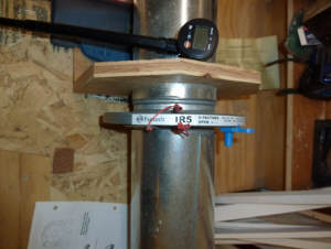
Closer view of the IR damper. |

And another. |
The blue lever on the IR damper allows you to adjust the how far closed the
damper diaphragm is.
The two red pressure taps allow you to hook up a monometer (or other pressure
measuring device) and the pressure across the damper is proportional to flow
rate. They provide tables to look up the flow rate from the pressure drop.
This IR damper system seems like a nice simple way to measure flow rate --
you don't have to worry about velocity profiles across the duct etc. It is
claimed to be pretty accurate.
The problem right now is that the the hot wire anemometer and the IR damper
give greatly different flow rates. Still trying to work this out.
Anything look goofy in this whole thing? Any suggestions?
Gary
November 17, 2010