
Search
The Renewable Energy site for Do-It-Yourselfers
Flow Distribution
Test -- Copper/Aluminum Collector
|
The test is intended to
check the evenness of the flow distribution through a collector made
from copper pipes in which both the risers and the manifolds are built
from half inch diameter pipe.
The
copper/aluminum collector uses half inch
copper pipe top and bottom manifolds. This allows the whole
collector array (risers and manifolds) to be built from half inch copper
pipe, and to use inexpensive standard half inch Tee fittings for easy
and cheap assembly.
Commercial collectors usually
use 3/4 inch or 1 inch manifolds, so the question is, do the half inch
manifolds on this homemade version provide a sufficiently even
distribution of flow in the collector, or is there a tendency for the
risers near the supply end of the collector to get more flow at the
expense of the risers at the far end of the collector?
An additional question is how
wide can this kind of collector be made without the half inch manifolds
causing an uneven flow distribution?
To get an idea how even the
flow is, I removed the glazing on the prototype collector, and then set
up a flow of water through the collector and let it go until things
stabilized. I then measured the surface temperature at the top and
bottom of each riser using a non-contact, IR thermometer.
The idea is that areas getting lower flow will be hotter because there
is less flow to remove the heat. If the risers at the supply end
of the collector are getting more flow, they should be running cooler,
and this should show up in the surface temperature measurements.
|
|
|
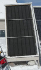
Collector with glazing
removed |
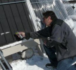
Measuring temperature of
absorber surface at riser tube |
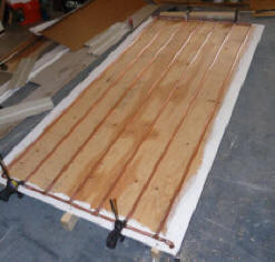
Absorber grid before
installing aluminum fins. |
Note: If you can think of a better way to check the flow distribution through
the risers,
please let me know...
The Test:
February 7, 2009
Clear and sunny with a light and
variable breeze.
Tambient = 41F
Tcollector surface with no flow =
124F to 127F (depending on breeze)
Flow rate = 1.5 gpm or 0.047 gpm/sqft
| Top
Manifold |
|
79F |
85 |
85 |
88 |
87.5 |
104.5 |
82.5 |
|
Riser 7
+9.5F |
+15.5 |
+13.5 |
+14 |
+12.5 |
+28 |
Riser 1
+13 |
|
69.5F |
69.5 |
71.5 |
74 |
75 |
76.5 |
69.5 |
| Bottom
Manifold |
The table above is
arranged like the copper tube array for the collector -- each column represents
a riser. There 7 risers numbered 1 to 7 from right to left.
The manifolds that
deliver water to the risers are marked "Top Manifold" and "Bottom Manifold".
The supply water
from the tank enters the bottom manifold at the lower right corner, then along
the bottom manifold with some water flowing up each riser. The hope is
that the flow divides evenly, and a roughly equal amount of flow goes up each
riser.
The flow from each
riser is collected by the top manifold, and exits the collector at the top left
corner.
The top row of
numbers are surface temperatures taken near the top of each riser.
The bottom row of
numbers are temperature taken near the bottom of each riser.
The row of numbers
across the center of the table show the temperature rise from the bottom of
riser temperature to the top of riser temperature.
So, for example,
riser 1 has a temperature near the bottom of 69.5F, increasing to 82.5F at the
top for a 13F rise.
We attempted to get
all the measurements within a short period of time, but there is probably some
variation over the about 1 minute it takes to get the readings. There are
also variations due to small changes in collector construction at the spots
measured.
There are other
little inconsistencies coming from slight variations in breeze, sunlight, the IR
thermometer itself etc. -- but the data appears to be consistent enough to reach
some conclusions.
Conclusions:
1. Overall, the top
and bottom of riser temperatures, and the temperature rises are pretty even.
This indicates to me that the flow is fairly even through the risers.
So, from a flow distribution point of view, the half inch manifold appears to be
working OK.
The exceptions
to this even flow are:
Riser 7 (the
left most riser) appears to have a consistently lower temperature rise,
indicating that it is getting somewhat more flow than the other risers.
This may be due to the fact that the manifold to riser connection for
the last riser is an elbow, while the other manifold to riser
connections use Tees -- the rounded flow path of the elbow may result in
more flow.
The riser 2
temperature rise is consistently greater than the others. This may
indicate that there is some kind of partial blockage -- perhaps a solder
blob from my sloppy soldering? The fact that it is still
substantially lower in temperature at the top of riser 2 than the
surface temperature with no flow indicates that it is still getting
enough flow to work OK .
2. It appears to me
that the collector could be wider than it is, and a half inch manifold will
still given even enough flow to work OK.
I'm not sure what
the limit is, but I would think that a 6 ft wide collector would be OK.
A caution:
Commercial
collectors are sometimes connected in banks by coupling the manifolds together
end to end. With the large, 1 inch manifolds, as many as 5 collectors can
be connected in this way. This should not be done for collectors
with half inch manifolds.
One fairly compact
arrangement that would work with half inch manifold collectors and give a large
collector area is to:
Make two large
area copper pipe collector arrays -- perhaps 6 ft wide by 10 ft high each
for a total area of 120 sqft.
Place the two
arrays side by side -- they could even share a common housing.
Arrange plumbing
so that the supply for the left collector is at its lower right corner, the
supply for the right collector is at its lower left corner (so the two
supplies are right next to each other at the center of the housing).
The return for
the left collector is at its upper left corner, and the return for the right
collector is at its upper right corner.
So, the two
supply lines are right next to each other, and can share a common supply
line. The two return lines could be run to the center of the
collector, and be Tee'd into a shared return line.
The shared
supply and return lines should be at least 3/4 inch diameter. For a
drain back collector, these lines could be PEX.
If you need more
collector area, than this arrangement could be replicated multiple times.
Remember that if
this is a drain back system, the copper pipe arrays must be "clocked" a bit
in the housing so that the lower manifolds slope down toward the supply
line. So, the left collector is rotated a bit clockwise, and the right
collector a bit counter clockwise. This allows the collector to
fully drain for freeze protection. The supply and return lines back to
the storage tank must also be sloped toward the tank.
Similar test on wider collector
with 3/4 inch manifolds...
Gary February 7, 2009


