Search
The Renewable Energy site for Do-It-Yourselfers
Variation in Riser
Flow for Wide Solar Water Heating Collectors
This is a test to get an idea how
much variation in flow there is between the risers in a wide collector.
The motivation for the test was that
1) there seems to be little data out there confirming that this manifold
arrangement actuall does distribute fluid evenly to all of the risers, and 2) a
poor distribution was reported on one collector of this type...
The test collector is has a
bottom manifold (supply) and a top manifold (return) connected by many vertical
risers that are spaced about 6 inches apart.
The intent of this design is to
distribute the heat transfer fluid equally among the risers so that each riser
receives the same flow.
The collector used for the test is my
93.3 sf, 11 ft wide collector:
133 inches wide by 101 inches
high -- 93.3 sf.
Risers are half inch copper and
about 100 inches long -- 20 risers in all spaced at about 6 inches.
Manifolds (top and bottom) are
3/4 inch copper, and about 130 inches long.
Risers are connected to manifolds
with standard copper 3/4 by 1/2 inch reducing T's.
(these reducing T's are used at all riser locations, including the first and
last riser)
Water enters the collector at the lower right by
3/4 inch copper supply pipe.
Water exits the collector at the upper left by 3/4 inch copper return pipe.
Vertical rise from tank water level to top of collector is 9.9 ft
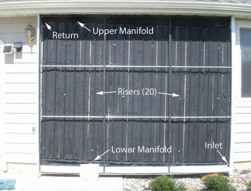
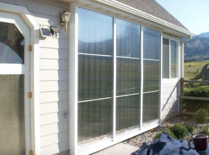
Collector with
glazing off showing manifolds, risers, and supply and return
It is difficult to measure the actual
flow in each riser directly (anyone have a good idea on how to do
this?). So, I took the approach of removing the glazing, and taking
temperature measurements at the bottom, middle, and top of each riser.
Risers that are being fed with a good supply of water should show a progressive
rise in temperature from top to bottom, with the bottom temp not much higher
than the supply water (tank) temp. Risers that are getting low or no flow
should show little change in temperature, and high temps, since the water flow
is not removing heat from them.
This is not a perfect test in that
the collector glazing has to be removed to take the temperatures, breezes effect temp readings a bit, it takes
8 minutes to do a full set of readings (so things may vary a bit), and the IR
temp gun just has a little reading to reading variation. So, don't over
interpret differences of a couple degrees -- it may just be the test setup
variation. The test does appear to be good enough to pick up serious flow
distribution discrepancies.
To do the test, I lowered the tank
temp, which was at 149F down to about 110F by running the pump overnight. This
was necessary as, with the glazing off, the collector would lose heat with 149F
rather than gaining heat.
The top 10 inches of the collector is
shaded by the roof eave at this time of year -- this combined with the vertical
tilt keeps it from overheating when stagnated even with the Twinwall glazing.
Click on pictures for full size

Collector with before glazing was removed |
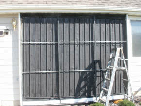
Collector with glazing removed for test. |
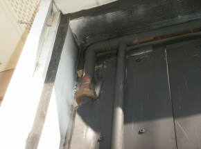
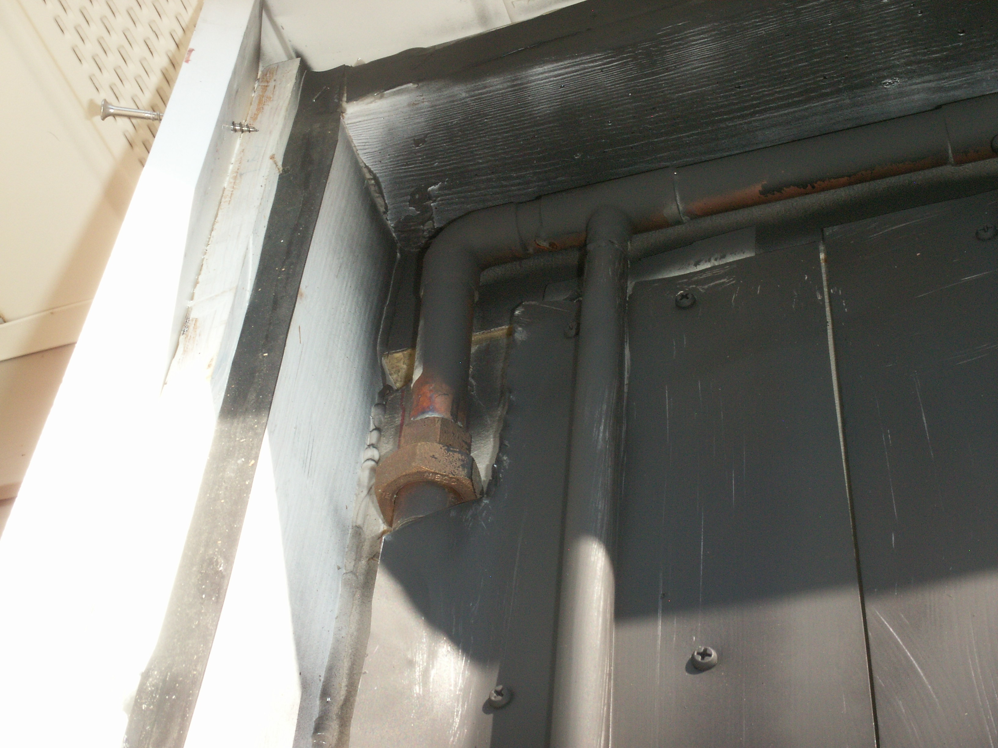
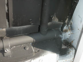
Upper left corner of collector.
The elbow and union are part of
the return plumbing. |
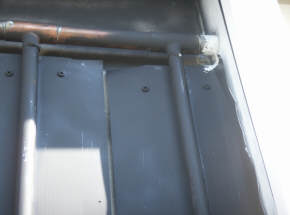
Upper right of collector.
The white painted thing on the end is
a regular copper end cap. |
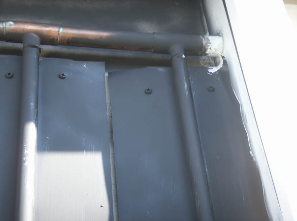
Lower left of collector.
Terminated with copper cap. |
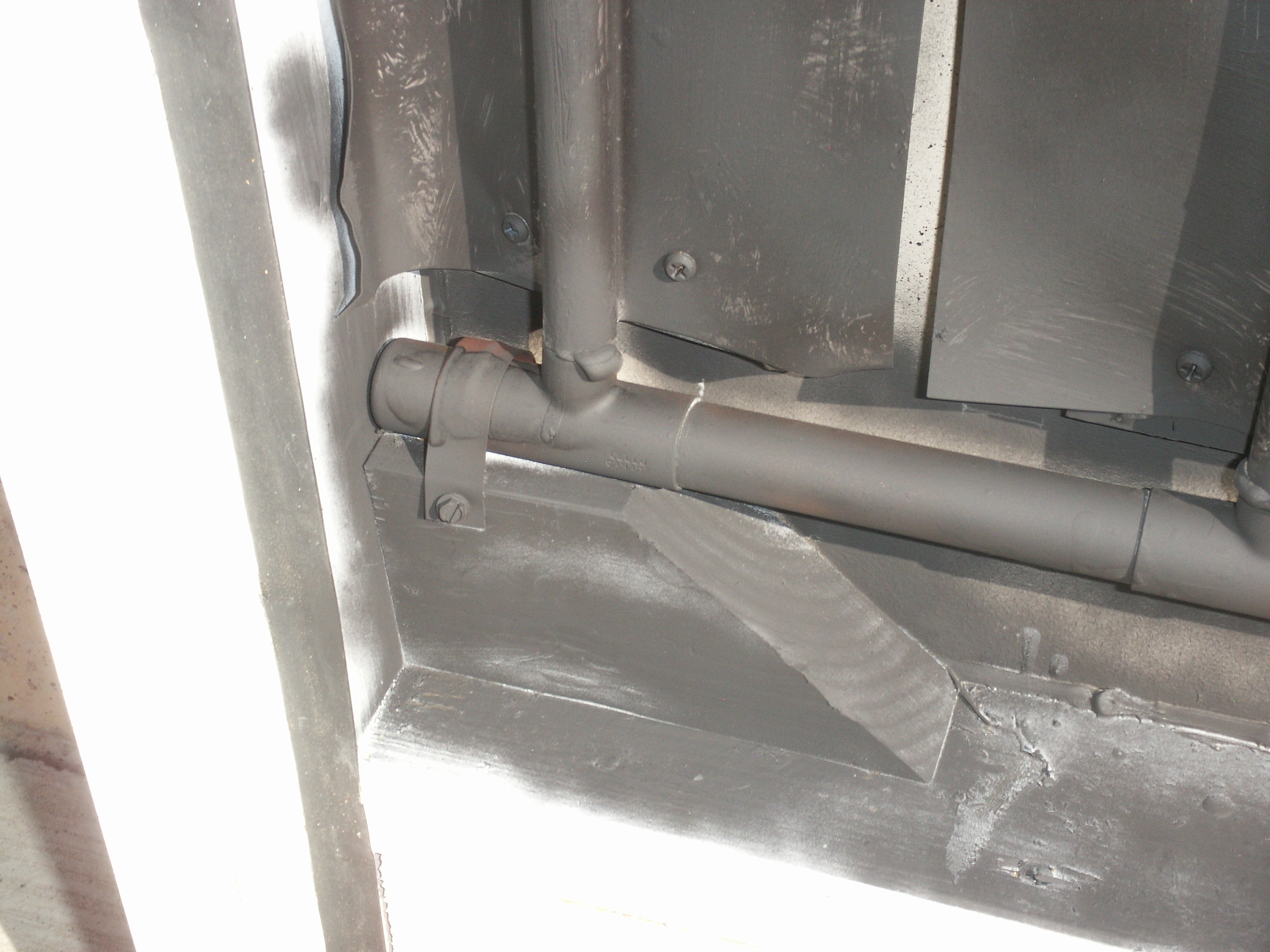
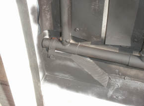
Lower right of collector.
The supply is the vertical pipe coming
in from below via the elbow. |
Results
The table shows the results of
measuring the temperature of each riser at the bottom, middle, and top with flow
through the collector and with the glazing off.
The bottom temp measuring point was 8
inches above the lower manifold, and the upper temp was measured at 14 inches
below the top manifold (about 4 inches below the shadow that is shading the top
10 inches of the collector). The middle reading was taken half way between
the upper and lower points.
|
Riser No |
1 |
2 |
3 |
4 |
5 |
6 |
7 |
8 |
9 |
10 |
11 |
12 |
13 |
14 |
15 |
16 |
17 |
18 |
19 |
20 |
|
top |
124 |
123 |
123 |
124 |
126 |
129 |
124 |
128 |
126 |
132 |
127 |
125 |
129 |
|
125 |
128 |
126 |
123 |
123 |
122 |
|
mid |
123 |
122 |
121 |
123 |
124 |
124 |
120 |
125 |
123 |
125 |
125 |
125 |
125 |
|
124 |
123 |
123 |
123 |
123 |
120 |
|
bottom |
122 |
117 |
119 |
117 |
119 |
117 |
115 |
119 |
118 |
119 |
120 |
121 |
119 |
|
117 |
117 |
115 |
116 |
120 |
115 |
| |
|
|
|
|
|
|
|
|
|
|
|
|
|
|
|
|
|
|
|
|
|
Time |
12:47 PM |
|
|
|
|
|
|
|
|
|
|
|
|
|
|
|
|
|
|
12:56 PM |
| |
|
|
|
|
|
|
|
|
|
|
|
|
|
|
|
|
|
|
|
|
|
Temp rise |
2 |
6 |
4 |
7 |
7 |
12 |
9 |
9 |
8 |
13 |
7 |
4 |
10 |
0 |
8 |
11 |
11 |
7 |
3 |
7 |
So, the distribution (to me) seems
pretty even.
There is some variation in the temp
rise in the various risers, but no really dramatic differences.
The far left riser does appear to be
getting more flow. This may be real, as it also showed up on one other
run, but the bottom of riser temp of 122F looks a bit suspect. Another
factor may be that the left most and right most risers are trimmed a bit in
width to fit inside the case -- so, they probably get a little less gain that
other risers.
On the two other runs I did, the left
riser had a more normal rise on one of them (6F), and a low temp rise in the
other.
Sun conditions were very clear.
There was a light and variable
breeze, which may effect temperature readings a bit.
From the differential controller
readout:
Tank temp bottom = 110.6F
Tank temp top = 111.7 F
Tcollector = 127.9F (as
reported by the differential controller)
All of this was done with the pump
turned on with a flow rate of 4.6 gpm (0.049 gpm/sf).
The pump is a Grundfos 15-58 3 speed
pump on low speed.
The pump is mounted just outside the
tank at a level about 30 inches below the water surface.
A 3/4 inch copper U-tube connects the
pump inlet to the water near the bottom of the tank.
The supply run of 3/4 inch copper is
probably only about 8 ft from pump to bottom of collector.
The return line is also 3/4copper,
and is about 20 ft long.
All plumbing is sloped toward the
tank.
The return line ends inside the tank
in the airspace above the water.
Before the pump was turned on, but
after the glazing was removed, the absorber temp ranged from 128F up to 140F.
In the course of 3 runs with the
glazing removed, the tank temp went up about 2F -- so, even with the glazing
off, it was collecting heat.
Bonus Data
Since I had to take the tank lid off
to measure flow rate (having forgotten the previous measurement). I went
ahead and took these measurements at each of the 3 speeds of the Grundfos 15-58
pump:
| Pump speed |
Flow rate
gpm |
Flow Rate/sf |
Power
watts |
Time to full flow
seconds |
drain back time
seconds |
| Low |
4.6 |
0.049 |
59 |
50 |
28 |
| Med |
6.4 |
0.068 |
75 |
35 |
28 |
| High |
7.5 |
0.08 |
87 |
30 |
30 |
Even at the low speed, the 15-58
provides a good brisk flow rate, which is precisely in the middle of the range
recommended by Heliodyne for their collectors (0.025 to 0.075 gpm/sf).
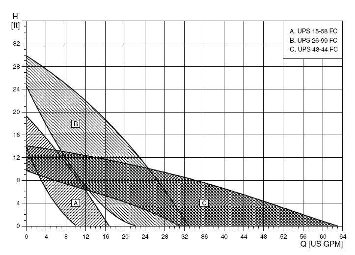
The 14 ft static head at low speed
filled the collector and established full flow conditions without any hesitation
or difficulty clearing air.
This static head is 40% greater than
the actual vertical head from tank level to top of collector.
Flow measurements were taken by
timing how long it took to fill a half gallon container with a stop watch.
Power measurements with a KillAWatt
meter. For comparison, the power consumption numbers in the
Grundfos spec are 60 watts low speed, 80 watts mid speed, 87 watts high
speed.
In the pump curves below, the 15-58
is the one marked "A" -- 14 ft static head at low speed.
Thom's Collector
This test was done as a result of the
uneven distribution of fluid to the risers on Thom's 24 ft wide collector.
When Thom did the same measurements his collector shows a pattern of lots of
flow in the end risers, but little flow in the middle risers. Thom's
collector is done as two 12 ft wide collectors -- each of the 12 ft wide
collectors is very similar to my 11 ft wide collector.
Its still not clear what the reason
for this the poor flow distribution in Thom's collector, in that his collector
is built in very much like mine. Two potential differences come to mind:
1) on Thom's collector, the end riser is connected to the manifold with an elbow
rather than a reducing T, and 2) even with a garden hose hooked up to supply
more pressure, Thom's flow rate to half of his collector (which is similar in
size to my full collector) is only 2.5 gpm.
The connection of the end risers with
elbows rather than T's seems like a small issue, but this
earlier test indicates it might have a significant effect.
We are still trying to work out why
Thom's collector is showing such a larger variation in riser flow. These
are the discussion threads on SolarHeat and Simply Solar groups. If you
have any ideas on this, please post them.
SolarHeat post...
Simply Solar post...
Gary August 19, 2010