Search
The Renewable Energy site for Do-It-Yourselfers
DIY Solar Collector:
Optimizing the Thermal Conductivity of the Fin to Riser Tube Joint
I've received a some
emails wondering if the silicone caulk used between the
aluminum fins
and copper or PEX tubing is really a thermal benefit, and suggesting
that perhaps the silicone isolates or insulates the riser pipe from the
aluminum fin, and may do more more harm than good. Others
have have suggested that something other than silicone caulk with
greater thermal conductance might work better to fill the gap between
the aluminum fin and the riser tubes. I've done some thinking,
testing, and calculating on this issue, and the raft of stuff below goes
over all this. My thanks to all the people who made these
suggestions!
From my knothole, the bottom
line is that the silicone caulk remains a good choice because it shows good
thermal performance and has several other very desirable
characteristics. And, that any thermal improvement
resulting from substituting a more conductive material would likely be small. But, please read the material below, and see if
you agree -- or maybe have another approach to suggest?
If you are
wondering
what in the world this is all about ... |
|
The current reasoning for using
silicone caulk between the fins and tubing
The reasons I've included the
silicone caulk between the fin and tube on collectors built to date are: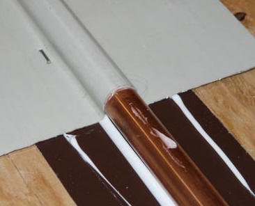
-
The silicone caulk fills any
small gaps between the aluminum fin and the tube that would otherwise be filled with
air. The silicone has a
thermal conductance around 0.25 w/m-C and air has a thermal conductance around 0.025
w/m-C -- so the silicone is ten times more conductive than air, and I
believe that this results in better performance. The
small panel tests comparing air in the gap vs silicone caulk in the gap (see
below) tend
to support this. The calculation of the thermal resistance of a very
small gap filled with air or filled with silicone caulk (below) also tend
to support the idea that 1) the gap filled with silicone will have better
thermal performance, and 2) that the thermal benefit of a more conductive
material than silicone caulk will not be large. The one caveat here is
that the amount of silicone must not be excessive, and must not result in a
larger gap because any excess silicone is not squeezed out -- This is
discussed below, but I don't thing that
its a problem in practice.
-
When you staple the grooved
aluminum fin over the tube very tightly, you should get a very small gap to
no gap between the fin and the tube. The silicone caulk is a
good adhesive, and will tend to keep this small to no gap condition for the
life of the collector. It basically glues everything into place and
keeps it there. If you don't put the silicone in, the thermal
expansion and contraction may work the staples over time and may allow a
larger gap to develop between the fin and tube over time -- mind you, I
don't know that this would happen, and it may not.
-
Silicone caulk is a very good
material to use in collectors -- it has a long track record of standing up
to the very difficult environment inside of collectors for a very long time
without degradation. Many materials don't do well inside of
collectors.
-
Silicone caulk remains
flexible after curing, so it can handle the differential thermal expansion
between the fin and tubing.
-
Silicone caulk acts as a barrier
to prevent galvanic corrosion between the aluminum fin and the copper pipe
-- it prevents the entry of water from condensation into the area between
the fin and the tube and it physically separates and protects the aluminum
and the copper. It adds to the protection offered by the paint finish.
-
Silicone caulk is cheap,
safe, and readily available.
This sounds a bit much like a
commercial for silicone caulk, but (honest) I don't sell it make it. I do
think we are lucky to have such a good material for use in collectors, and that
it is cheap and easy to find.
Looking at the Suggestions for
Improvement
The suggestions for improvement
include:
-
Leave out the silicone caulk on
the idea that it does more harm than good. An offshoot of this is that
the silicone caulk may result in a larger gap between the fin and tube if it
is not well squeezed out.
-
Use a thermal grease or heat sink
compound that has a higher thermal conductivity than silicone caulk.
-
Us a silicone caulk that has been
formulated for high thermal conductivity. There are some specialty
silicone caulks that use fillers to achieve higher thermal conductivity.
On item 1, I don't see the merit of
this. The test and the calculation below both indicate that a silicone
caulk filled gap will have significantly better thermal performance than an air
filled gap. The test panel and calculation indicate an about 2 to 6%
improvement in heat output for collectors with a silicone filled gap over an air
gap.
Based on some informal testing and
sectioning of one of the test panels, I don't believe that the silicone results
in a thicker gap as long as you take some care in the assembly. This is
basically because the excess silicone can be squeezed into the area between the
grooved fin and the flat aluminum base plate -- that is, the excess silicone
does not have to travel to the ends of the fin groove.
On item 2, I am leery of using a
non-curing thermal grease or heat sink compound. I don't think that these
materials would glue the fin and tube together as the silicone caulk does, and I
think that having the fin and tube glued together is important to prevent the
gap between the fin and tube from increasing over time as the collector is
worked by thermal expansion and contraction (of course, I may be totally wrong
about this :) In any case, the calculation says that the gain in
collector efficiency for using a more thermally conductive material would be
small.
On Item 3, I do think there would be
a small gain (see calculation below) if one could find and obtain a high thermal
conductivity silicone caulk. I've asked for a sample of CHO-THERM
1641, which is such a caulk, and will test it if the sample comes through.
Based on the calculation below, I would not expect to see a large improvement in
performance, but I'd like to see how the test comes out. If anyone has a
good source for a high thermal conductance silicone caulk, please let me know.
Update: May 2011 --
here is result of testing a high thermal conductivity silicone ...
Small Panel Test -- Silicone in Gap
vs Air Gap
The aim of this test is to compare
the performance of a collector with silicone caulk in the gap between the fin
and the riser tube to one with air in the gap.
Click on pictures for full size
|
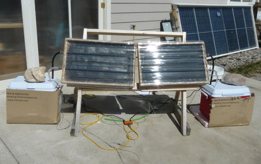
The two test panels and reservoirs
during the test. |
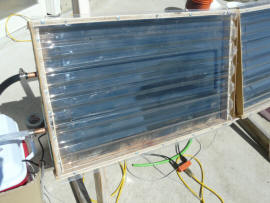
Closeup of panels -- same size
and orientation. |
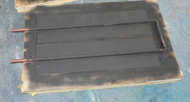
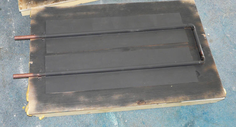
One of the test collectors
before adding the glazing. |
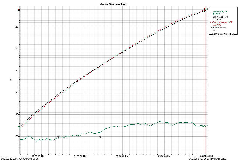
Test Setup:
Red line -- reservoir temperature
for the panel with the silicone filled gap
Solid black line -- reservoir
temperature for the panel with the air filled gap
Green line -- ambient
temperature.
Both reservoirs filled with 29
lbs of water.
Absorber area for both collectors
is 2 sqft.
Glazing is SunTuf corrugated
polycarbonate.
Back insulation is 2 inches
polyisocyanurate foam board.
Reservoir temperatures are logged
with an Onset Computer U12 logger using 10K thermistor temperature sensors
immersed in the reservoirs at the pump inlets.
Flow rate is about 0.4 gpm
(relatively high to make sure flow does not limit heat transfer and to keep
the reservoir well mixed).
The pumps are small (3 watt), submersible fountain pumps that are located in
the reservoirs.
This is a
small panel test in which the performance of
two small collectors is compared. One collector uses aluminum fins and
copper tubes with a layer of silicone caulk between the fin and the tube.
The 2nd collector uses the same construction with no silicone between the fin
and tube. Each collector heats a 29 lb charge of water in its own
insulated reservoir. The reservoir water is pumped through the collector
using a small submersible pump. The collector that raises the temperature
of it's reservoir the most is the better performer. The idea is that since
each collector is the same size, is heating the same amount of water, and is
exposed to the same sun, the only difference in reservoir temperatures will is
be due to the difference in the construction of the two collectors -- in this
case, the fin to tube gap being filled with air or filled with silicone.
The performance plot shows the
silicone filled gap collector starting about 1F below the air filled gap, and by
the end of test, the silicone filled gap collector reservoir is about 1F warmer
than the air gap reservoir.
Results:
| Collector Construction |
Start temp |
End temp |
temp Rise |
% of base |
| Test1: Silicone filled gap vs air filled gap |
|
|
|
|
| |
Copper tubes - Aluminum Fins -- Air in gap |
76.07 F |
127.60 F |
+51.53 F |
base |
| |
Copper tubes - Aluminum Fins -- Silicone in gap |
75.20 F |
128.00 F |
+52.80 F |
+2.5% |
| |
So, the panel with the silicone caulk
filling the tiny gap between the copper tube and the aluminum fin showed about
2.5% better performance. I did two similar tests with the collector that
uses PEX tubing and aluminum fins. The results were similar with about 4%
better performance for the silicone filled gap collector.
Rough Calculation Comparing Silicone
in Gap to Air in Gap
This is an analytical estimate of the
performance improvement you might expect to see for the silicone filler in the
gap between the tube and fin:
Thermal Conductivity of air = Kair =
0.025 w/m-C
Thermal Conductivity of silicone
caulk = Ksil = 0.25 w/m-C
Consider a 1 meter long segment of
aluminum fin and tube:
Solar collection area for this 1
m of fin and tube = (0.152m wide)(1 meter long) = 0.152 sqm
Solar Radiation on 1 m of fin and
tube = (1000 watt/sqm)(0.152 m^2) = 152 watts
Assuming a typical 50% collector
efficiency, the solar radiation going into 1 meter of tubing = (152
watts)(0.5 efic) = 76 watt
So, the 1m of fin must transfer
76 watts to the tube through the air or silicone filled gap. What is
the temperature difference across the gap that is required to transfer this
76 watts?
Heat transfer area - fin to tube
= (1.580 cm)(Pi)(100cm) = 496 sqcm = 0.0496 sqm = Aht
This is the heat transfer area
from the fin to the tube that the 76 watts must be transferred through.
Assume that the average thickness
of the gap is 0.004 inches = 0.0102 cm = 0.000102 m = Tgap
(equal to a thin sheet of paper).
Heat Transfer across the gap = Qgap =
(Aht)(dTgap)(K/Tgap)
Where dTgap is the temperature
difference across the gap -- rearranging for dTgap:
dTgap = (Qgap) (Tgap) / ((Aht) (K))
So, for the silicone filled gap, the
temperature difference required across the gap to transfer 76 watts is:
dTgap = (76 watt) (0.000102 m) /
((0.0496 sqm)(0.25 w/m - C)) = 0.63 C = 1.1 F
If you use
this collector
efficiency calculator, and assume typical collection conditions (60F
ambient, 120F storage temps), then the collector efficiency drops from 52.3%
down to 52% -- a drop in efficiency of 0.3% -- this is the result of
increasing the absorber (fin) temperature by 0.63 C (1.1F) to overcome the
thermal resistance of the 0.004 inch thick silicone caulk layer. This is
equivalent to a 0.6% drop in heat output from the collector compared to a a
collector with a perfect fin to tube connection.
With air in the gap instead of
silicone caulk, the temperature difference across the gap would have to be:
dTgap = (76 watt) (0.000102 m)
/ ((0.0496 sqm)(0.025 w/m - C)) = 6.25 C = 11.2 F
Using the collector efficiency
calculator, the efficiency would drop from 52.3% down to 48.6% -- a drop of
3.7%. This is a bit more than the 2.5% result from the test above, but
generally in agreement.
So, both the test panel and the
calculation suggest a gain in collector output in the area of 2 to 6% for
filling the gap between the fin the tube with silicone caulk. In addition,
the caulk bonds the fin and tube together tightly so that there is no tendency
for them to separate as thermal expansion and contraction work the collector
over time.
If one were able to buy and use a
thermally conductive silicone caulk like this
CHO-THERM 1641, the temperature drop across the gap would be reduced by a
factor 3 to about 0.2 C (0.4F), and the efficiency drop to overcome the thermal
resistance of the gap would be reduced to only 0.1%. This would be a gain
in efficiency over the plain silicone of 0.2%, and a heat output gain of about
0.5% -- this is in the nice to get category, but probably not worth paying a
great deal more.
I've asked for a sample of the CHO-THERM
1641, and if they come through, I'll do a small panel test with it.
The calculation assumes that the
presence of the silicone in the gap does not make the gap any thicker. It
has been suggested that the gap might be thicker with the silicone because of
its resistant to being squeezed out. After some playing around with some
short sections of tube and fin to see how well the silicone squeezes out, I
don't think that this is a problem as long as firm pressure is applied when
stapling. Any excess silicone only has to work its way down to the bottom
of the tube where it is easy for it to be squeezed out between the bottom sheet
and the fin. I also sectioned one of the early test panels with a saw at 4
inch intervals, and did not see any evidence of the silicone resulting in a
larger gap. You do need to use moderation in applying the silicone to the
fin groove, and to use lots of pressure when stapling so that any excess
silicone is squeezed out. It is a good idea to just make a test section a
couple feet long, then let it cure for a day, and then cut across it in a couple
locations to see if you were successful in keeping the gap small. Spraying
a mist of water into the air around and in the fin gap before applying the
silicone will allow the silicone to cure more quickly.
Gary April 7, 2009