Search
The Renewable Energy site for Do-It-Yourselfers
Small Panel Tests
of copper and PEX collectors
The tests described below compare the performance of the traditional
solar water heating collector that uses copper tubing soldered or welded
to copper heat absorbing fins to these two less expensive DIY collector
options:
The PEX tubing/aluminum fin collector...
The copper
tubing/aluminum fin collector...
These two
collectors can be built as a DIY project for $4 to $6 per sqft compared
to the $25 per sqft (plus truck freight) for all copper commercial
collectors.
These tests look at
how well these DIY collectors perform compared to the all copper
traditional construction.
|
|
Page Directory
The Test Plan
and Setup
I built a small test collector for
each of the three collector types, and ran them
side by side with each connected to identical small insulated reservoirs
containing the same amount of water. During the test, water is pumped from
the reservoir through the collector and back to the reservoir -- the water
in the reservoir heats up as the test progresses. The collector with the better
performance heats the water in its reservoir to a higher temperature, and the difference in final
temperatures in the two reservoirs is an indicator of how much better one collector performed than the
other.
I learned this technique form
Alan Rushforth, and I like it -- its easy and cheap to setup, and since each
collector is subjected to the same sun exposure, same reservoir size,
same amount of water, same ambient temperature, same wind, same pump, same heat losses... a lot of the variables that drive you crazy in
trying to compare collector performance are eliminated.
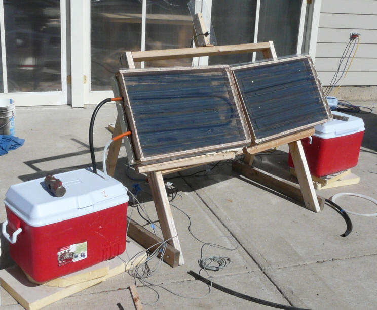
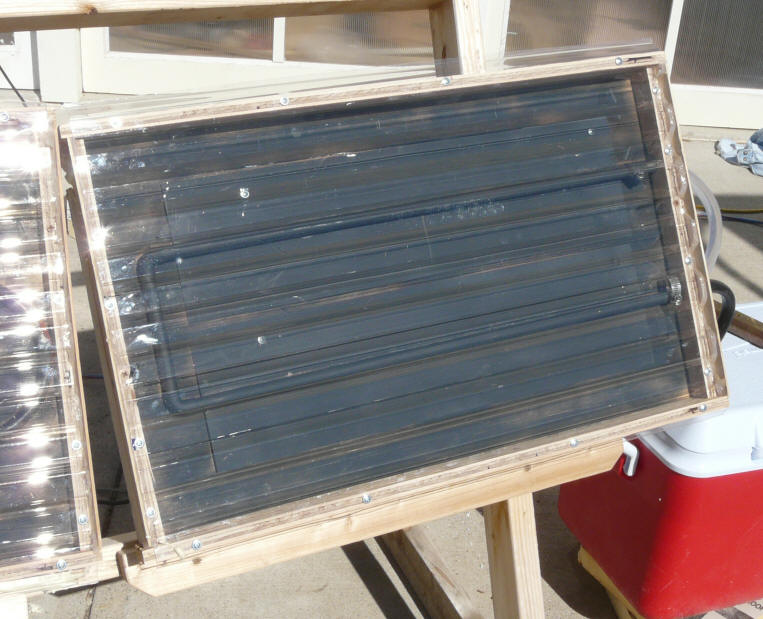
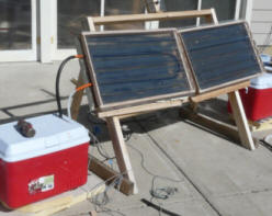
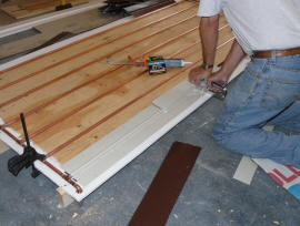
The picture above shows the test
setup. The collector construction being tested is on the left,
and the baseline collector using copper pipe soldered to copper fins is on
the right. The absorber and glazed area are the same for the two
collectors, and they both face the same direction. The two ice chests are each
loaded with 41 lbs of water. Identical, small submersible pumps are located
in each ice chest and pump water into the lower hose on each collector.
The water returns to the ice chest through the upper hose. Every attempt
is made to make the conditions for the two collectors identical so that only the
efficiency of each collector impacts the final temperature difference in the
reservoir temperatures.
Sun intensity is measured with an
Apogee pyranometer that is visible on the upper part of the stand -- it faces
the same direction as the collectors.
The reservoir temperatures are
monitored and logged with thermistor temperature sensors using an Onset Computer
logger.
Ambient temperature is logged at a
nearby, shaded location. The reservoir temperature sensors are located
near the pump intake on each reservoir, but the temperature is nearly constant
throughout the reservoir.
The flow rate through the collector
is fairly brisk (about 0.4 gpm) -- this keeps each collector operating at its
best efficiency, keeps the collector pipes filled, and keeps the reservoir
well mixed and at a uniform temperature.
Each pumps draws 3 watts (as measured
on a Kill-A-Watt meter), and this would tend to heat the water in the reservoirs
a bit -- about 0.25 F per hour. While the reservoirs are
insulated, they still lose some heat, and this would cause reservoir temperature
to drop a little -- about 0.4F per hour at mid test. But, the pump heating
and reservoir cooling effect each panel by the same amount, and have a small net
effect compared to the solar heating of the water.
Construction of the Test Collectors
Baseline Collector with Copper
Tubing Soldered to Copper Fin:
|
This panel has the same construction
as many traditional commercial solar collectors. It uses half inch copper
pipe to convey the heat transfer fluid. The copper pipe is soldered
continuously to copper fins to provide a very good thermal connection from the fins
to the pipe.
The copper fin is 0.018 thick --
somewhat thicker and more conductive than is commonly used in commercial
collectors. The fins are painted flat black.
The collector is glazed with 93%
transmittance SunTuf corrugated polycarbonate glazing -- very close to the
tempered high transmittance glass used on most commercial collectors. The
polycarbonate used also has similar IR transmittance characteristics to glass,
so the losses out the glazing should be about the same.
The back of the panel is insulated
with 2 inch polyisocyanurate insulation to R13.4 -- somewhat more than is used
on most commercial collectors.
The absorber on this collector is
painted flat black. This is typical of a number of
commercial collectors, but some commercial collectors use a selective coating
instead of black paint, and these result in about a 6%
improvement in efficiency under typical conditions. There are some
DIY selective coatings that could be used to gain back some of this if desired,
although they are generally not as good as the commercially applied selective
coatings.
Anyway, the idea was to make the
performance of this collector be as close to a typical all copper commercial
collector as I could, so that it could act as a baseline to measure the
performance of the other collectors. This collector is referred to as the
"baseline" below.
|
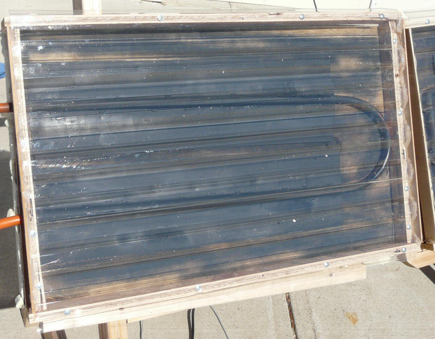
All Copper Test Collector

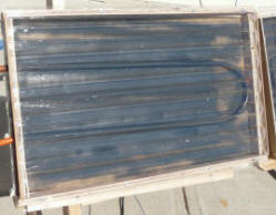
All copper test collector. All collectors
are identical in size, glazing, insulation,
reservoir size, pump, ... |
|
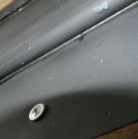
Close up of copper tube, copper fin, and solder joint. |
PEX Tubing with Grooved Aluminum Fin
Collector:
|
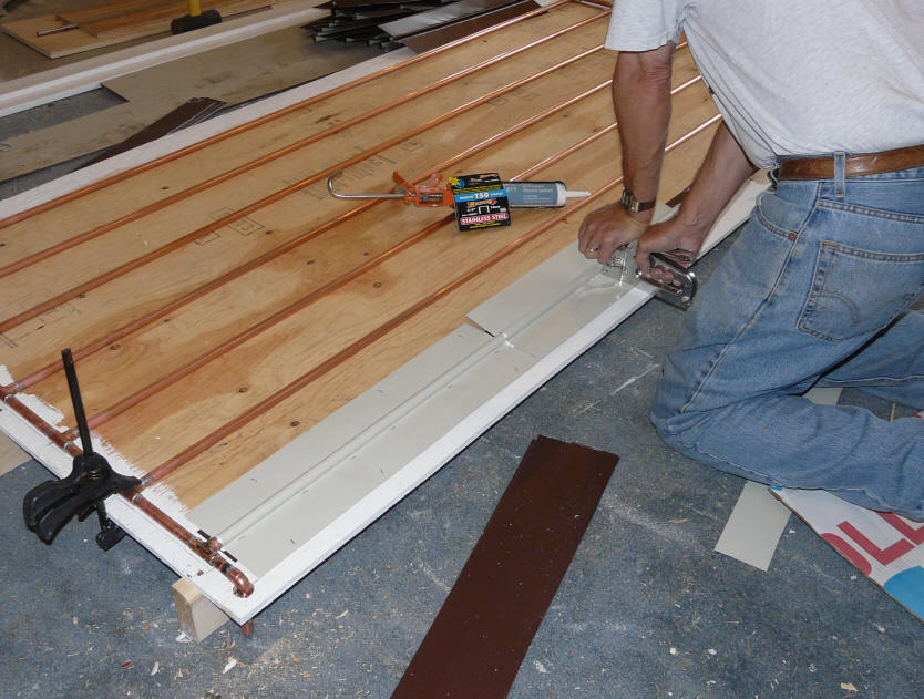
This collector uses half inch
PEX-AL-PEX to convey the heat transfer fluid.
The fins are made from 0.018 aluminum sheet. Each fin has a groove formed in it that fits
the PEX tube snugly.
There is a 2nd narrow sheet of
aluminum under the PEX tube (see picture) that overlaps the grooved piece on each side of the
tube, so the tube is essentially wrapped for its full circumference with
aluminum fin.
The absorber is painted with
the same flat black paint as is used on the copper baseline collector.
A silicone caulk is used to fill any
tiny gaps remaining between the PEX tube and the aluminum fin. The idea of
using the silicone caulk is that it is about 10 times more conductive than the
air that would otherwise fill the gap.
The construction details for this collector are shown here ...
|
The PEX/aluminum test collector. |
|
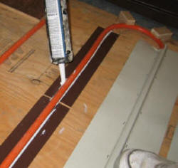
PEX tubing and aluminum
heat collection fins. |
Copper Tubing with Grooved Aluminum
Fin Collector:
|
This collector is constructed in
exactly the same way as the PEX collector described above except that instead of
PEX pipe, copper pipe is used.
So, this construction gives you the
high conductance tube wall of copper along with the easy assembly and the less
expensive aluminum fins, and no soldering of the pipe to the fin.
The construction
details for this collector are shown here ...
|
 |
Test Results
Three tests have been done to date --
the results are discussed below and shown in the table below .
Test 1: Copper Baseline vs PEX
Collector with Grooved Aluminum Fin:
The PEX tube with grooved aluminum
fin collector does 84.2% as well as the baseline all copper collector.
Considering the low thermal conductivity of the PEX tubing wall, this is (I
think) very good.
Test 2: Copper Baseline vs Copper Tube with Grooved Aluminum Fin:
The copper tube with grooved aluminum
fin with silicone between does an amazing 96% as well as the baseline all copper
collector.
See also the temperature plot below
for Test 2 below.
Test 3: Copper Baseline vs Copper Tube with Grooved Aluminum Fin:
This is the same as Test 2 except
that half the water (20 lbs) is used in the reservoir so that higher
temperatures will be reached.
The idea is to make sure that the
relatively low temperatures reached in tests 1 &2 were not effecting the
performance differential between the baseline and test collectors. It
shows the same 96% of the baseline collector performance.
See also the temperature plot below
for Test 3 below.
This table shows starting and ending
temperatures for the two reservoirs over the full length of the test.
| Collector Construction |
Start temp |
End temp |
temp Rise |
% of base |
| Test1: Copper Tube - Copper Fin VS PEX tube
- Aluminum Fin |
|
|
|
|
| |
Copper tubes - copper fins (soldered) |
56.5 F |
107.8 F |
+51.3 F |
base |
| |
PEX tubes -- Aluminum Fins (groove and seal) |
56.1 F |
99.3 F |
+43.2 F |
84.2 % |
| |
| Test 2: Copper Tube - Copper Fin VS Copper Tube -
Aluminum fin |
|
|
|
|
| |
Copper tubes - copper fins (soldered) |
55.9 F |
115.1 F |
+59.2 F |
base |
| |
Copper tubes - aluminum fins (groove and seal) |
56.8 F |
113.6 F |
+56.8 F |
96.0 % |
| |
| Test 3: Copper Tube - Copper Fin VS Copper
Tube - Aluminum fin |
|
|
|
|
| |
Copper tubes - copper fins (soldered) |
52.8 F |
145.6 F |
+92.8 F |
base |
| |
Copper tubes - aluminum fins (groove and seal) |
53.2 F |
143.0 F |
+89.8 F |
96.7 % |
I think that a lot of reason for the
relatively small performance hit is the tight fitting groove in the aluminum
that wraps around most of the tube and provides a large contact area, as well as
the silicone to fill any remaining paper thin gaps.
I
Further improvement might result from
using a high thermal conductivity silicone between the tube and fin. These
are available, but I could not find a US source for small quantities.
Another reason that the performance
is closer than one might expect looking at the difference in tube wall
conductivity is that the all configurations are limited by the thermal
conductivity of the boundary layer of water just inside the tube wall -- it does
not matter how conductive you make the tube wall, you are still limited by this
boundary layer conductivity.
Tentative Conclusions
Commercial Copper Collectors
Commercial copper collectors offer
known high performance, long life, and good resistance to high
temperature stagnation temperatures for all tilt angles. But, they are
expensive (about $25 per sqft), and shipping is costly and can be very
frustrating (it took three tries to get an undamaged set of commercial absorber
plates for my Solar Shed collectors).
PEX Tubing -- Aluminum Fin Collector
From a cost effectiveness point of
view, the PEX collector does very well. If you are
willing to put the labor in, you can build the PEX collector for about 1/6 th the
cost of a good commercial collector, and only suffer a 15% loss in
performance. This makes the PEX collector 5 times as cost
effective as a commercial collector on a BTU per dollar basis. In most cases, the loss in performance can be made up
for just by making the collector a bit larger. You can literally build the PEX collector for about what it costs to ship a commercial collector to your
house!
The PEX collector must be protected
in some way from stagnation conditions. Collectors that are
stagnated in the summer at tilt angles close to the local latitude will develop
temperature that are (I think) to high for PEX -- temperatures over 250F.
In my case, I use a high tilt angle to control summer stagnation temperatures.
I think that the combination of a relatively large collection area coupled with
a high tilt angle (which gives improved winter performance) will give very good
year round performance and a larger winter time solar fraction. If
these methods of controlling stagnation temperatures are unacceptable, and you still want a
low cost collector, consider the
collector that uses copper pipe and aluminum fins (see below).
The commercial collector should have
a life of 30+ years and will probably need very little maintenance during that
time. The PEX collector may well also last 30+ years, but will likely need
some help along the way. By help, I mean that it will likely need some
painting and may need replacement of the polycarbonate glazing. The glazing on
my PEX collector is SunTuf polycarbonate, which is
guaranteed for "life", but my guess is that 15 years before new
glazing is needed
might be more reasonable. If carefully painted, the case should have
similar life and maintenance to a wood window or door frame. My
guess is that the PEX and aluminum fins will last a very long time, but this has
yet to be shown.
Because the baseline copper collector
is more efficient than the PEX collector, and there will be some weather conditions
under which the copper collector will be harvesting a little heat and the PEX
collector will be getting nothing. An example might be a cold day that has
a not so thick overcast. Without having looked at this in detail, I would
guess that this will amount to very little over a full season. When you
get to these kind of weather conditions, no collector is going to be collecting
much useful energy because there just is not that much solar radiation coming in
and the collector efficiency is low -- I believe that the bulk of the useful energy you collect over a season is
going to come from sunny or part sunny days.
Copper Tubing -- Aluminum Fin
Collector
For many people, I think that this
collector may be the best all around choice.
It provides nearly the same
performance as the baseline all copper collector, and about 14% better
performance than the PEX collector.
An advantage of this
copper tubing/aluminum fin collector compared to the PEX tube collector is that
it will not require special protection from stagnation temperatures. While
its not good to subject any collector (including commercial collectors) to long
periods of stagnation, the polycarbonate glazing, copper pipe, aluminum fins,
and silicone are all high temperature materials that should do well under
stagnation conditions.
At $6 per sqft it is $2 per sqft more
expensive than the PEX collector, but still a small fraction of the $25 per sqft
that commercial collectors commonly cost.
The build time is similar to the PEX
collector.
Small Panel Test Performance Plots
Test 1 Plot: Copper Baseline
Collector vs PEX tube with grooved aluminum fins
Long dash line is the baseline copper
tube/copper fin collector:
Half in copper pipe
Copper fin material -- 0.018 inch
thick -- fins are 6 inches wide
Copper fin is soldered to the
copper tube
Flat black paint
Solid line is the PEX collector:
Half inch PEX-AL-PEX tubing
Aluminum fin material -- 0.018 thick grooved to fit the PEX tubing -- fins
are 6 inches wide
Narrow aluminum strip under the
tube.
Silicone caulk to fill the paper thin gap between tube and aluminum
Flat black paint
Dash line is ambient temperature in a
shaded area about 10 ft away from collector
Green line is solar radiation on
collector plane in watts per sq meter
Reservoir is charged with 41 lbs of water.
Test 2: Copper Baseline Collector vs
Copper
tube with grooved aluminum fins
Solid line is the Copper Tube with
Aluminum Fin Collector:
Half inch copper pipe
Aluminum fin material -- 0.018 thick grooved to fit the the copper tubing -- fins
are 6 inches wide
Narrow aluminum strip under the
tube
Silicone caulk to fill the paper thin gap between tube and aluminum
Flat black paint
Long dash line is the baseline copper
tube/copper fin collector:
Half in copper pipe
Copper fin material -- 0.018 inch
thick -- fins are 6 inches wide
Copper fin is soldered to the
copper tube
Flat black paint
Sun and ambient temperature log did
not come out.
Ambient temperature was 63 to 65F.
This was a very clear sunny day --
sun intensity was probably similar to Test 1.
Reservoir is charged with 41 lbs of water.
Test 3: Copper Baseline Collector vs
Copper
tube with grooved aluminum fins (20 lbs of water):
Test 3 is the same collectors as Test
2, but the water charge in the reservoirs was reduced from 41 lbs down to 20
lbs. This allows the collectors to get to higher temperatures to make sure
performance does not change with higher temperatures.
This is a ratio of 1.2 gallons of
water per sqft of glazing -- on the low end of what solar water heaters might
use.
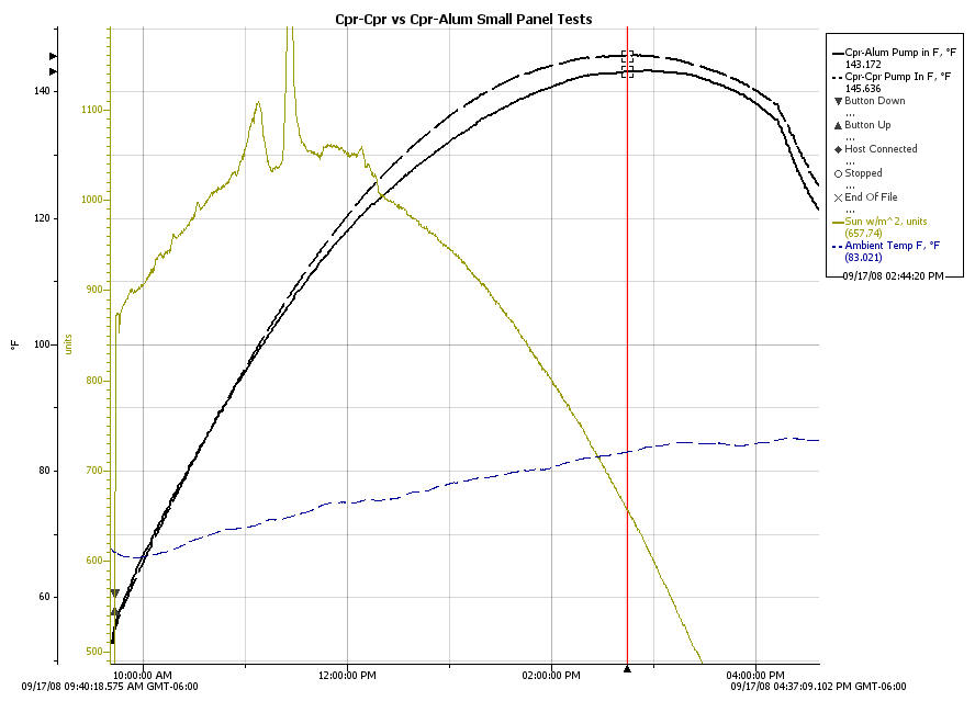
Solid line is the Copper Tube with
Aluminum Fin Collector:
Half inch copper pipe
Aluminum fin material -- 0.018 thick grooved to fit the the copper tubing -- fins
are 6 inches wide
Narrow aluminum strip under the
tube
Silicone caulk to fill the paper thin gap between tube and aluminum
Flat black paint
Long dash line is the baseline copper
tube/copper fin collector:
Half in copper pipe
Copper fin material -- 0.018 inch
thick -- fins are 6 inches wide
Copper fin is soldered to the
copper tube
Flat black paint
Puky green line is solar radiation in
watts/sq meter
Dashed blue line is ambient
temperature F
Very clear sunny day.
Reservoir is charged with 20 lbs of water.
Follow-on
Small Panel Tests
Some additional small panel tests
that have been done since the ones above:
Silicone caulk in
tube to fin gap vs nothing in gap...
Higher thermal conductivity silicone caulk in tube to fin gap vs regular
silicone...
Gary September 12, 2008, September
28, 2008, May 26, 2011