Comparing the Performance of Two DIY
Solar Water Heating Collectors -- CPVC vs Copper
Sometime back I had a brief go at a
solar
water heating collector made from CPVC with aluminum fins. At
the time it seemed interesting, but not as good as some of the other
options for building collectors.
Scott Davis has taken a whole new look at the CPVC collector and come
up with a design that places the risers closer together, and uses a flat
aluminum sheet for the absorber plate. This makes for a design
that is inexpensive and easy to build. Scott's initial testing of
the collector indicated good performance.
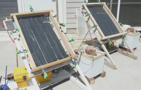
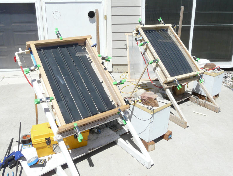
Side by side test of the two collectors.
I have to admit that I was a bit skeptical of the performance of the
new design due to the poor thermal connection between the risers and the
aluminum absorber sheet, but I've had a go at testing a collector with
copper risers and six inch wide aluminum fins against Scott's CPVC
design, and the CPVC does quite well -- it is only about 5% short of the
performance of the copper/aluminum collector.
So, this page covers the performance test, a stagnation test, some IR
pictures to try and see a bit more about what's going on, and a final
comparison of the two collector designs on things like cost, build,
durability, ...
I built the test collector as close as I could to Scott's collector as
described in his video. About the only thing I changed was to tighten up
the riser tube spacing to (hopefully) get a bit better performance.
The test collector absorber dimensions are 2 ft wide by 3 ft high.
This is the size I picked when building the
Sun Simulator as the best compromise
between not dimming the lights in the whole neighborhood when it comes on and
having it larger enough to get good results. For a real collector, you
would, of course, want it to be much larger.
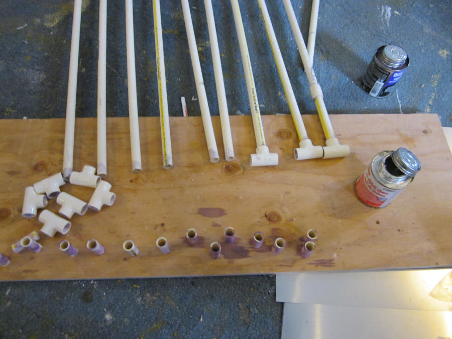
Here are a few construction pictures:
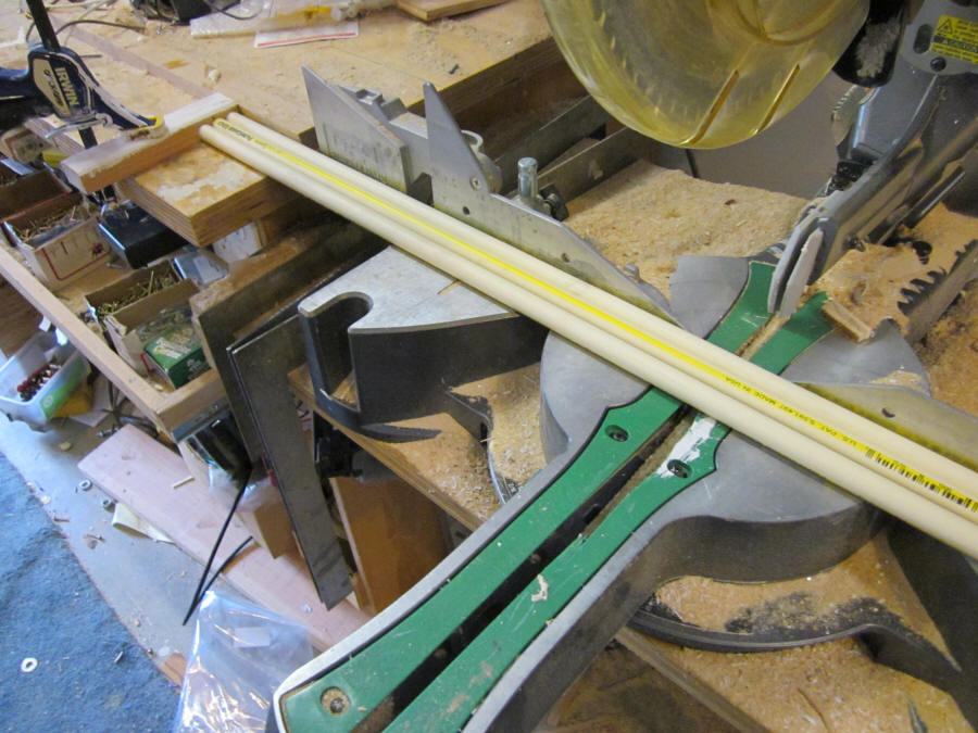
Cutting the risers.
The shears they sell for cutting plastic pipe
work just as well.
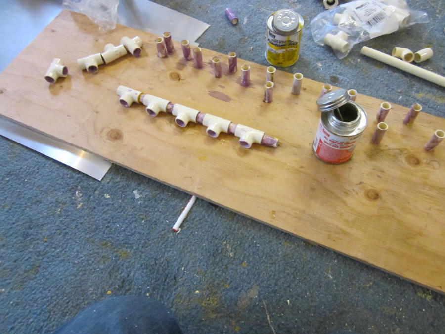
Starting to put together the headers.
The short straight pieces connect the T's
to make each header.
Solvent gluing the headers together.
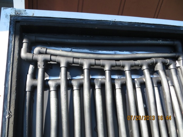
Gluing the risers into the top manifold.
Finished top manifold with risers glued in.
Starting the bottom manifold.
Glue the T's to risers first, then add the
short pieces of straight pipe between the T's.
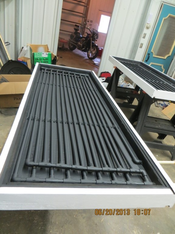
Finished CPVC tube assembly.
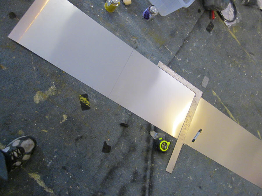
Cutting out the aluminum sheet for the
collector continuous fin.
This is 0.01 thick alum flashing material.
First piece of flashing in place.
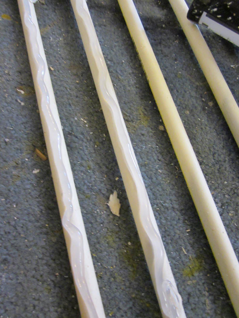
Applying the silicone to the riser tubes.
The silicone provides a thermal and
mechanical bond between the CPVC
and the aluminum absorber plate.
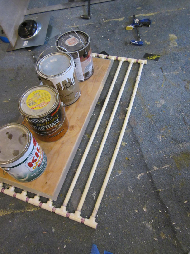
Weighting the alum to keep it in close contact
with the riser tubes until the silicone sets.
The completed CPVC absorber in
its collector box.
In the pictures above, the CPVC is just as easily cut with the inexpensive
shears they sell for that purpose. Or, any kind of wood cutting saw
you may already have will work. The purple primer I used on the
joints is not really necessary if you use the "Yellow" CPVC cement -- I just use
the primer out of force of habit.
I applied a fairly generous bead of silicone along the top of each riser
before putting the alum flashing on. I then flipped it over and added
silicone as needed, and then went down both sides of each riser with my finger
to form a fillet of caulk between the riser and aluminum flashing. Then
flipped it over, and put a flat piece of plywood over the alum with weights
until the silicone cured. Idea was to get as good a conductive path
between fin and risers as possible.
The box that the absorber goes in is made from 3/4 plywood sides. The
back is 1 inch polyiso that is foamed in place with Great Stuff foam in a can.
The glazing for this test is a single sheet of about 3/32nd inch thick Acrylic
sheet. The center to center spacing of the risers is 2 3/8ths
inches.
Both the glazing and the back are setup to be easily removed so that IR
pictures can be taken without the glazing (which is opaque to IR).
The collector goes together very easily.
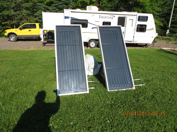
The other collector is made with half inch copper riser pipes and aluminum
fins. The fins were pre-grooved to fin snuggly around the riser tubes.
Other than size, the construction is just
like this collector...
Test Setup
I had planned to test the CPVC collector on the
Sun Simulator, but I'm still having some trouble
getting up to the full sun area light levels, and rather than waiting to get
that sorted out, I decided to do a side by side outdoor test. The
side by side test method tests two identical size collectors outside in the sun
at the same time. Testing the two collectors side by side, its easier to
measure which one is doing better without having to worry about variations in
sun, temperature, wind, ... This is similar to the
solar air heating
collector testing that Scott and I did last year, and these
earlier side by side
tests.
The two collectors each with its own reservoir.
Each of the two identical, insulated reservoirs was charged with 26.9 lbs of
water at about 70F. A collector's performance is proportional to the
temperature rise it achieves in its reservoir.
The two collectors were pointed in the same direction at the same tilt -- the
direction was set to provide nearly direct incidence. An Apogee
pyranometer was mounted on the collector glazing frame such that it measured the
solar intensity in the plane of the glazing.
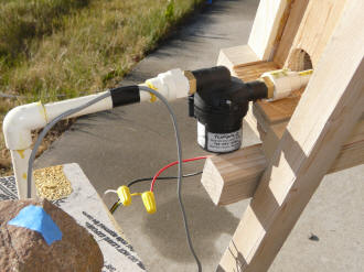
The water from the reservoir was pumped through the collector using
TopsFlo pumps.
The water from the pump entered the collector on the bottom right corner, and
returned from the collector to the reservoir by a tube from the upper left
corner of the collector.
Each collector is 2 ft wide by 3 ft high. I attempted to make the area
of the two absorbers exactly the same, but somehow the CPVC absorber ended up
about a half inch wider, which should make very little difference.
Each collector is glazed with a single layer of 3/32 inch Acrylic plastic.
The glazing is mounted to a wood glazing frame, and this frame is set up for
easy removal to take IR pictures without the glazing.
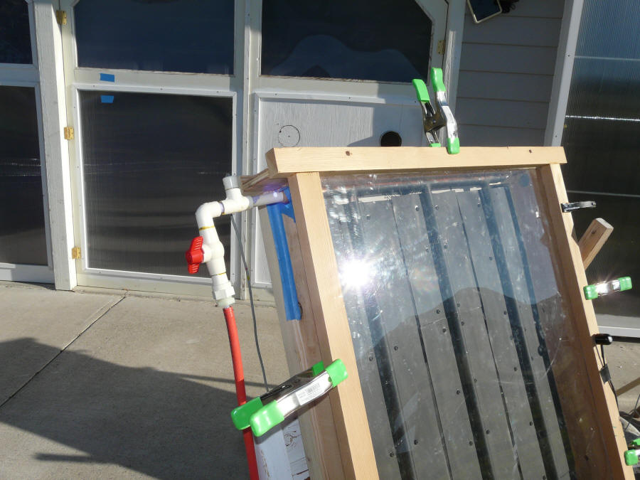
The CPVC collector.
The clamps hold the glazing on and
allow for quick removal.
The copper/alum collector.
Return tube from upper left corner with throttling valve.
Apogee pyranometer on the right side.
The supply line from reservoir with
the Topsflo pump.
The flow rate was adjusted so that is was approximately the same on both
collectors. The flow rate used was somewhat higher per sqft that is
normally used on solar water heating collectors, but not a lot. The higher
flow rate should make both collectors slightly more efficient.
I would have preferred a cooler day, but that does not seem to be in the
cards any time soon, so I went with the relatively warm day, but took the
reservoir temperatures all the way up to 160F, so there was a good differential
between ambient and collector absorber temperatures.
There are all sorts of things that happen in the course of these tests that
are not accounted for: the reservoirs lose some heat through the insulation and
pick a little heat from the sun, a little of the pump power gets into the water
as heat, the wind goes up and down a bit, the sun varies a bit, and on and on.
But, the nice thing about these side by side tests is that all of these things
happen to both collectors, so they don't effect the performance comparison
between the two.
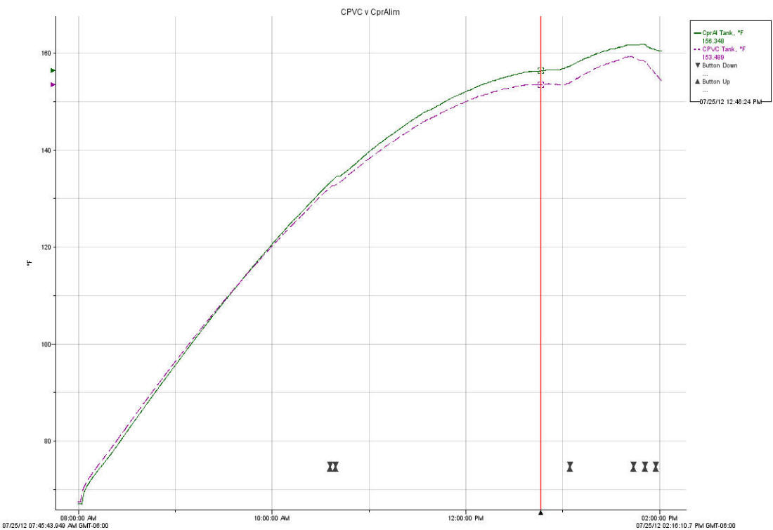
Performance
The plot just below shows the temperatures of the reservoirs attached to each
collector. The greater the temperature gain of the reservoir, the more
heat the collector is producing during the test.
Purple dash line
CPVC Collector reservoir temperature (F)
Green solid line
Copper riser - alum fin collector reservoir temperature (F)
The jog in the two curves at about 12:50 pm was a stop to take of the glazing
of each collector and get IR pictures of the absorber without glazing. I
then put the glazing back on and let the test go a while longer. The two
collectors were reoriented to face closer to the sun at the same time, which
explains the greater rate of temperature increase in the reservoirs for both
collectors from 1:00 pm to about 1:45 pm. It looks like the reservoir
temperatures would have made it up to about 170F had I continued the test
longer.
The plot just below shows the solar radiation values with the pyranometer set
to read the radiation on the plane of the glazing. The other curve is the
ambient temperature during the test as measured just behind the collector in the
shade of the collector. I think that the ambient temperature sensor
location is not ideal, and the temperatures it registers are on the high side.
For example, at 12:12pm, the ambient temperature logger reads 86F, while the
temperature in full shade on the north side of the barn 50 ft away reads 74F.
As you can see from the sun curve, it was a very clear day with good sun.
The wind was generally light.
Purple solid line
Sun (watts/sm)
Green line
Ambient temperature (F)
This table shows start and end temperatures of the reservoirs and relative
performance over the 4 hours of the test.
Collector
Start Temp (F)
End Temp (F)
Temp Rise (F)
Performance Relative to
Base
Copper/Alum
70.9
156.3
85.4
base
CPVC/Alum
71.9
153.5
81.6
0.955
Again, I am surprised by how well the CPVC/alum collector performs relative
to the copper/alum collector. I thought that the line contact between the
CPVC tube and the aluminum fin would take more of a toll, but apparently the
closer spacing of the risers allows the CPVC collector to come within 5% of the
copper/alum collector.
Other
I did notice a bit of film on the inside of the CPVC collector glazing.
At first I thought I had a small leak and that it was condensation, but when I
took the glazing off, its more of an oily film. This may just be
associated with some outgassing of the new components. It was easy to wipe
off, and I'll see if it comes back again on future tests.
You can see the film in this picture to the left, and a place where I wiped
across
it with my finger.
The CPVC collector tends to bow out a bit toward the collector glazing when
the sun it on it. I think this is due to the different expansion rates of
the CPVC and the aluminum, but it may also be due to the fact that the absorber
fits snuggly in the box and may be be restrained by the box. In any case,
I would not restrict this bowing, as it probably helps to reduce the amount of
thermally induced stress across the glue line. It might be a good
idea for tall collectors to cut the aluminum so that it is broken up into (say)
3 runs of 3 ft rather than one run of 9 ft. It would also be good to
hang the collector in the box from the top manifold, and then just support the
bottom in such a way that its free to move vertically. This is the same
way I mounted my large copper/alum collector, and it appears to work fine and
reduces thermal strain on the absorber plate.
Analysis and Potential Improvements
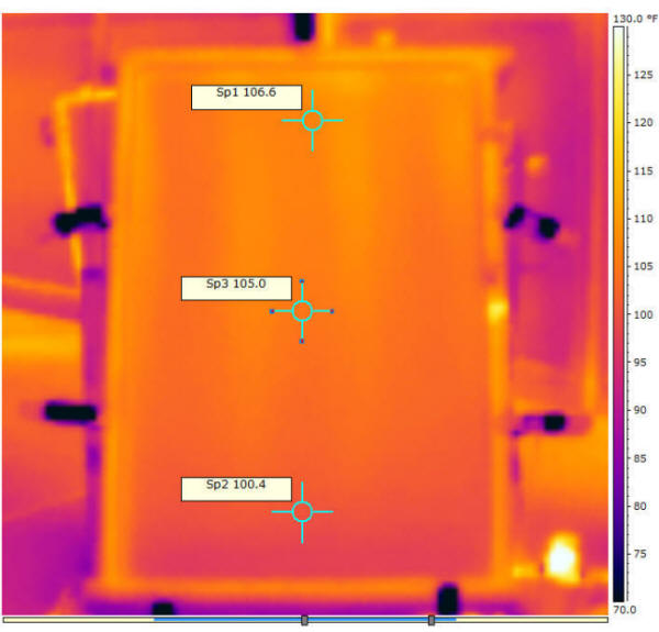
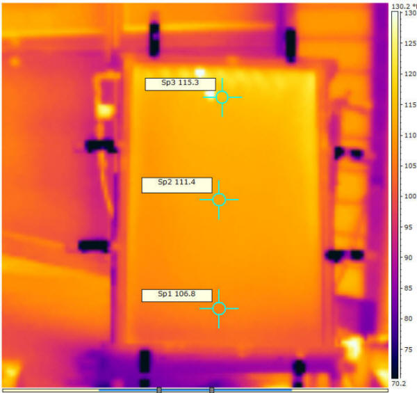
Glazing IR pictures
The IR pictures just below are taken around 10:45 am when the reservoir
temperature is about 132F. The copper/alum glazing averages about 6F
cooler than the CPVC collector glazing, indicating that it is losing less heat
through the glazing, which is likely caused by the average temperature of the
cpr/al absorber running cooler than the CPVC absorber.
The Acrylic glazing is nearly opaque to the IR heat radiation that the camera
senses, so the pictures show the temperature of the glazing, not the absorber.
The pictures are adjusted to show the same temperature range (70F to 130F) --
so, visual comparisons of the colors are valid. The little tags (eg "Sp1
106.6") show the temperature in degrees F at that point.
The copper/alum collector glazing temperatures.
The CPVC/alum collector glazing temperatures.
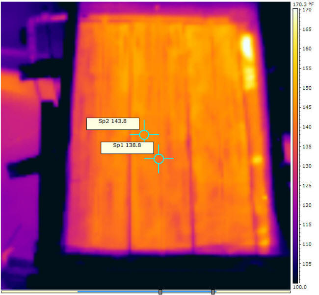
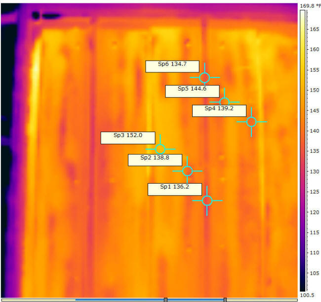
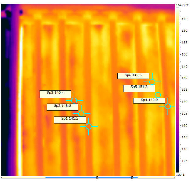
Poly Glazing IR Pictures
cpr/al collector through poly glazing
CPVC collector through poly glazing.
The two pictures above were taken around 1:55 pm with reservoir temps around
160F. The pictures were taken with polyethylene film glazing which
is fairly transparent to the IR heat radiation the camera sees, so, to some
degree, you see through the poly glazing and onto the absorber plate. The
fact that its showing temperatures that are lower than the reservoir temperature
indicates (I think) the poly glazing is not perfectly transparent to the IR.
Looking at the cpr/al collector, it shows a temperature of 139F right on a
riser tube, and 144F about half way out on the fin. This is what I would
expect -- in that the fin needs to have some temperature differential from the
outer edge of the fin toward the riser to transfer heat to the riser.
I'd say that the the fact that its hard to even see where the risers are is a
good sign that the thermal efficiency of the fin to riser joint is good.
The equivalent picture of the CPVC collector shows a temperature of 150F on
the riser tube, and 143F on the fin about half way between the risers.
This is puzzling in that the temperature differential is in the opposite
direction of what you would expect if the fin is transferring heat into the
riser. Not sure what is causing this -- it could possibly be a difference
in the emissivities of the riser and fin, but they are both painted with the
same flat black paint, so that seems unlikely. Perhaps its an indication
that the fins are not really doing much to transfer heat to the risers -- it
makes we want to try a version in which the risers are as closely spaced as
possible, and not fin at all is used. Any ideas on this?
Overall, the average temperature of the CPVC absorber appears to be a few
degrees hotter than the cpr/al absorber, as expected.
Fin IR Pictures -- No Glazing
These pictures were taken around 10:35 am with a reservoir temperature of
about 132F. The glazing was removed, and the IR pictures were quickly
taken to try and get the temperature distribution across the fin and riser as it
was with the glazing on.
cpr/al collector -- no glazing. Upper left corner.
CPVC/al collector -- no glazing. Upper left corner.
On the copper/al collector picture, it looks like in some places the fins are
doing a good job of getting the heat to the riser pipes without incurring a
large temperature rise, but there are a few areas where the out edge of the fin
is running hotter than one would like. On the right hand riser its also
pretty easy to pick out where the 3 inch wide backing strip of alum ends -- the
temperature differential is definitely a bit better in the area where the
backing strip is.
On the CPVC picture, there are some areas where the fins are running warmer
than the risers as you would expect, but also a few mysterious cool areas on
fins where they are running cooler than the adjacent riser -- puzzling.
In general the temperatures of both the risers and the fins are higher than the
corresponding temps on the cpr/al collector -- probably indicating the not as
good thermal conductivity of the CPVC.
Anyone see anything else in these pictures?
Potential Design Improvements
One variation that Scott has suggested and I would like to try is to reduce
the spacing between the CPVC risers to as low as the Tee's will allow (about 2
inches). I'd like to try this with and without the alum fin sheeting to
try and see how much the alum is contributing (if anything).
Another possibility would be to keep the relatively closely spaced CPVC
risers and work out a way to improve the thermal bond between the risers and the
aluminum sheet -- perhaps a set of grooves in the aluminum that the CPVC risers
could fit in? Even shallow grooves might work pretty well given the close
spacing of the risers?
Another possibility that would keep the easy build would be to use
pre-grooved fins (like Tom's fins) and increase the riser spacing.
Any other ideas?
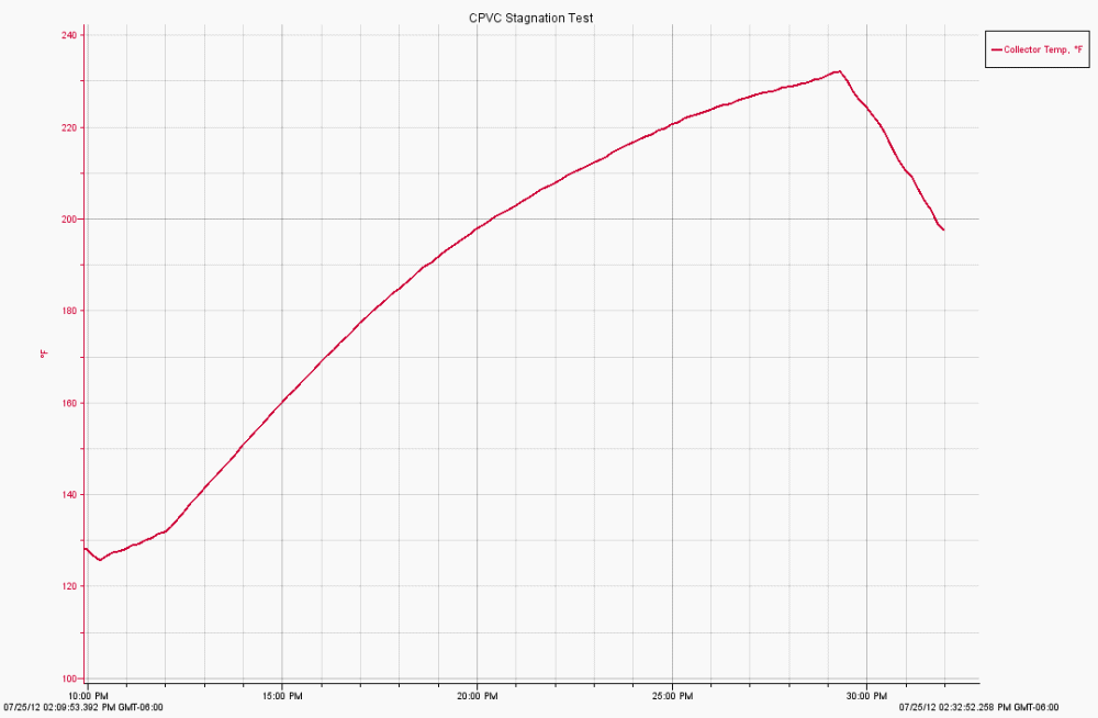
Stagnation Temperature Quick Test
Stagnation is the situation in which the collector is exposed to full sun
with no flow of water through the collector to remove the heat. The
collector continues to heat up until it gets hot enough so that it can lose all
the incoming heat via convection and radiation out through the glazing -- this
can result in quite high collector temperatures.
Since everything was all set up, I decided to do a quick stagnation
temperature test.
From the sun plot above, sun on the collector was close to 1000 watts/sm
(full sun). Ambient temperature was about 85F.
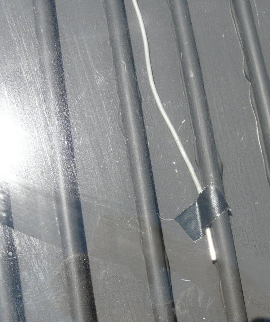
I removed the glazing and installed one of the logger sensors right next to
one of the CPVC tubes. It was just sitting loose next to the CPVC
riser tube, and might have registered higher temps if it was held in good
thermal contact to
the tube.
I turned off the flow and re-installed the glazing, and watched the
sensor temperature go up. It only took about 15 minutes to climb
from about 140 F up to 232F (See plot below). At that point I removed the
glazing as I did not want to damage the CPVC.
I think that this clearly shows that even for a single glazed collector,
stagnation temperatures on collectors mounted at normal tilt angles are too
high for CPVC. The 232F where I cut the test off is already to high
to expose the CPVC to and expect a good life. Clearly the temperature
would have kept going up and would likely have exceeded 250F -- too high.
The message here is that CPVC MUST be protected from high stagnation
temperatures.The steps that might work to do this that I know of
are:
- Mount the collector at a high tilt angle -- I would say
greater than 70 degrees.
- Do not use double glazing as this will increase
stagnation temperatures.
- Some form of ventilation of the collector might work,
but I would be sure to test it to be sure.
This is an area that could use some more work and testing.
Collectors mounted on vertical walls or at steep tilt
angle will not experience high stagnation temperatures, and CPVC or PEX will
work fine and provide a good long life.
Vertically
mounted collectors on walls work out well for space heating because the low
winter sun comes in nearly perpendicular to the glazing on a vertical collector.
For solar water heating collectors, a somewhat oversized collector at a steep
tilt angle also works well. It does not overheat in the summer because of the
high tilt angle, and the high tilt angle optimizes its performance during the winter
when the sun is more scarse. The end result is a high year round solar fraction.
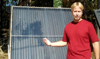
Here is one example of a
steeply tilted PEX collector with a 94% solar fraction... There
are a number of other examples of successful steeply tilted or vertical
collectors on the solar space
heating and solar water heating pages.
You could think about a system in which the collector is never allowed to
stagnate, but I don't think its a good idea in that over time pumps fail,
controllers fail, power fails, someone makes a change that causes a problem --
sooner or later your collector is likely to face stagnation.
Deciding Which Collector to Build
So, which is the best bet to build? It probably depends on what your
aims, skills, and budget are, but, I'll go out on a limb and offer the
following comparisons in a few categories:
Performance
Performance is a small plus for the copper/alum collector -- about 5%.
This is a relatively small gain.
Ease of Build
The CPVC collector is easier to build than the copper/aluminum collector.
I'd say it makes a good first project even if you have little to no DIY
experience.
The copper/alum collector is also easy to build. If you use fins with
preformed grooves (like
Tom's fins),
then the only significant difference in the two builds is that the joints are
glued on the CPVC and soldered on the copper/aluminum collector. I know
that soldering scares some people, but its really a very easy to learn skill,
and you should not be put off by it. With a little soldering practice on
some scrap, I'd say that the copper/alum collector could also be a first project
for someone with little DIY experience.
Cost
The table below is a cut at the cost of materials to do a 4 by 8 ft collector
for CPVC and Copper/alum.
The cost difference is less than I thought it would be -- copper/alum
is about 10% more than the CPVC.
Considering the performance difference, the cost per BTU would be about 5% more
for the copper collector.
Did I miss anything?
CPVC/Aluminum
Collector
Copper/Aluminum Collector
Item
Qty
Unit Price
Cost
Item
Qty
Unit Price
Cost
Insulation
4 by 8, 1 inch polyiso
1
$20.00
$20.00
4 by 8, 1 inch polyiso
1
$20.00
$20.00
Risers
1/2 inch CPVC
20
$3.91
$78.20
1/2 inch copper type
M
8
$11.22
$89.76
Manifolds
1/2 inch CPVC Tee
40
$0.20
$8.00
1/2 inch copper Tee
16
$0.65
$10.40
Glazing
2 by 8 ft sheet
2
$21.00
$42.00
2 by 8 ft sheet
2
$21.00
$42.00
Glacing
closeout
Foam closures
1
$7.62
$7.62
Foam closures
1
$7.62
$7.62
Alum fins
alum flashing 0.012
32
$0.86
$27.52
Preformed fins 0.018
32
$1.50
$48.00
Box back
4 by 8 plywood
1
20
$20.00
4 by 8 plywood
1
$20.00
$20.00
Box frame
2 by lumber
24
0.5
$12.00
2 by lumber
24
$0.50
$12.00
Silicone
caulk
caulk gun tubes
3
4
$12.00
caulk gun tubes
1
$4.00
$4.00
Paint and
misc
paint, screws, …
1
20
$20.00
paint, screws, …
1
$20.00
$20.00
Grand Total
$247.34
$273.78
Larger collectors will cost less per sqft.
Prices will vary depending on where you live and ups and downs with time.
Collectors against a wall can probably drop the box back plywood.
Prices from Home Depot and PEXSupply.com
Keep in mind that the collector is normally only about a quarter of the cost
of the full system.
I picked the 4 by 8 collector because a lot of people build in this size,
but, in general, I think bigger is better if you have the room -- the price and
labor per sqft go down as the collector gets larger, and you get proportionally
more heat from the collector.
Stagnation Temperature Related Limitations
Stagnation temperatures must be considered when using a CPVC collector. The
CPVC collector will work well when mounted vertically or at steep tilt angles
(70+ degrees), but should not be used at more shallow tilt angles. I
would not use double glazing on CPVC (or PEX) collectors because the double
glazing increases the stagnation temperatures. It is a good idea to
monitor collector temperatures the first season and make sure that your design
is working as you planned.
Another option might be to figure out a highly reliable
(preferably passive) way to vent the collector during stagnation events.
The Cpr/Alum collector can be used at any tilt angle and with single or
double glazing. That said, its a good idea not to subject any solar
collector at low to moderate angles to long periods of stagnation -- even
commercial collector manufacturers recommend covering or otherwise protecting
collectors that will be stagnated for long periods.
Durability and Life
I think that a well built copper/alum collector can be expected to last
around 30 years. This may require a glazing replacement at some point and
a little painting maintenance on the box, but its a pretty durable collector
with a good track record.
I think that the absorber of the CPVC collector is likely to have a shorter
life, but its really hard to say at this point what it might be. Maybe
there is someone that has experience with CPVC in this kind of environment that
could comment on this?
Two of the test collector -- single layer on left and dual layer on right.
The dual layer of CPVC design of Dan's.
Dan did a unique double layer of CPVC shown in the right photo above and compared it to a single layer design with and without an aluminum fin plate.
When neither collecotor had the aluminum sheet bonded to the CPVC, the double layer outperformed the single layer by about 10% on heat output.
When aluminum flashing was added to the single layer collector (but not to the double layer), the results were close to a tie with a slight advantage to the single layer with flashing.
Toward the end Dan experienced a loss of flow for unknown reasons and the resulting stagnation temperatures damaged the panel beyond further use -- so, be very careful of stagnation -- keep a high tilt angle.
Comments
What is your opinion? Any other factors that should be considered?
(comments below)
If you build a CPVC collector, please let us know how it goes, and take lots
of pictures.