Test on Downspout Solar Air Heating Collector
There has been an ongoing question on the
Yahoo Simply Solar discussion group about how much solar heat gets
transferred around to the back surface of the solar air heating collectors
made from gutter downspouts. If a significant amount of solar heat
gets transferred around to the back so that the back, front and sides of the downspout collector are
all hot, then this increases the absorber
to air heat transfer area, which is a major consideration on solar air
heating collector.
In the downspout collector design, ordinary aluminum downspouts are laid
side by side (or sometimes spaced apart a bit) to form the absorber.
Sun shines on one side of the downspout heating it up. Air is forced
through the downspouts and picks up heat from the hot downspout metal and
delivers it to the house.
If you want to see what a downspout collector looks like -- there are a
couple good examples on
Scott's
site...
One of the difficult design issues with solar air heating collectors is
providing good heat transfer between the solar heated absorber and the air.
Air is light in weight and low in heat capacity, so a lot of air needs to be
passed through an air heating collector, and it has to be done in a way that
puts a lot of the air in good thermal contact with the absorber.
Downspouts are thought to have an advantage here in that they provide a
large heat transfer area from absorber to air. But, this is only true
if the solar heat gets transferred around the downspout sides and back.
This test is aimed at finding out how well the downspout does in
transferring heat around to the sides and back.
The Test Setup
The picture below shows the not so ambitious test setup.
There are 3 aluminum gutter tubes about 31 inches long each. They are
spaced about half an inch apart. Each is foamed into an air supply
plenum made from rigid foam board insulation.
A small bathroom vent fan delivers air to the plenum.
Some 1 inch rigid foam board is used to cover the back side of the collector
and the east and west sides of the outer tubes. The insulation is made
so that it can be very quickly removed to measure the temperatures of the
back of the tubes. The idea of the insulation board is to keep the
heat loss from the back of the downspouts to the ambient air small, and more
closely simulate a real collector.
The temperature of the air coming into the fan, and the outlet
temperatures for the two outer downspouts were measured. The exit
velocity of the airstream was measured for all three tubes with a
Kestrel wind meter.
A thermal camera was used to get the temperatures of the front and back.
This was done by taking a thermal picture of the front, then moving around
to the back and quickly removing the back insulation and taking a thermal
picture of the back.
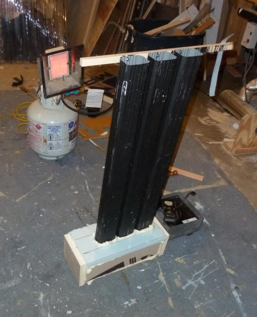
The picture on the right shows the three tubes glued into the plenum, but
without the back insulation panel installed.
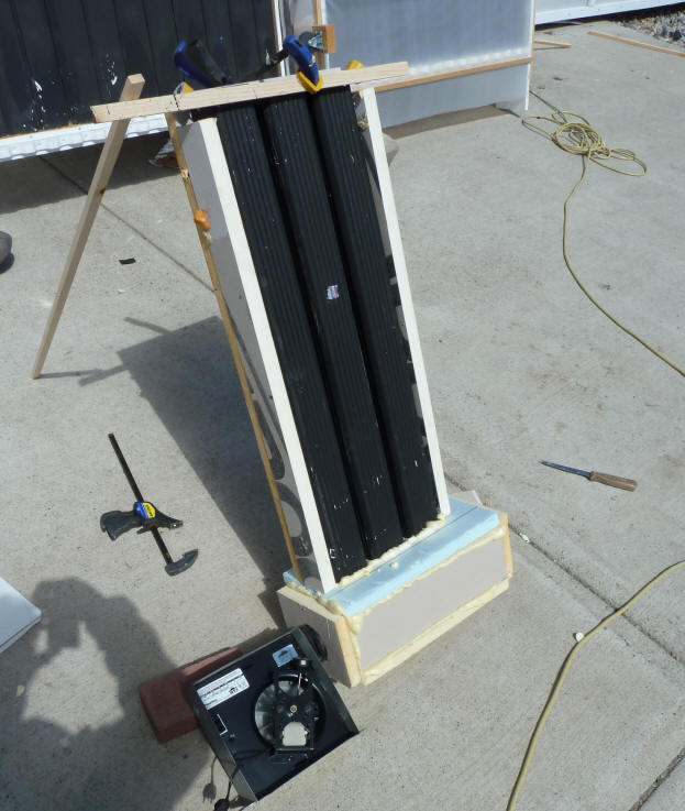
The picture on the left shows how the "collector" was setup during the
actual test. It was run this way for several minutes until
temperatures stabilized, and the the front thermal image was taken, the back
insulation was quickly removed and the back insulation picture was taken.
The downspouts measure 2 inches by 3 inches and are 0.016 inch thick
aluminum.
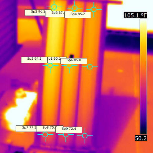
Thermal image from sun side after it stabalized. |
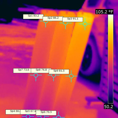
Thermal image from back (north) side taken at same time as image to
left. |
The left picture shows the collector from the front (sun side).
Temperature of the west tube is 96.2F on top, 94.3 half way down, and 77.2F
near the bottom. Remember, the west tube is on the left in the front
pic, and on the right in the back pic.
The right picture shows the collector from the back at the same time as
the left picture, and immediately after the back insulation board was
removed. The corresponding west tube temperatures on the back are
91.17F at the top, 81.5F in the middle, and 70.5F near the bottom.
Both thermal images are adjusted to show a temperature range of 50F
up to 105F, so areas of the same color have the same temperature in both
pictures. The "Sp" boxes show actual temperatures at those locations.
The images were taken with an FLIR I7 IR camera. Just from the thermal
pictures, its pretty clear that some heat is getting around to the back.
The temperatures are different on each tube because they were getting
quite different amounts of airflow.
The fan inlet air temperature was 56F.
For the west tube, flow rate was 240 fpm (10 cfm), and the air outlet
temp was 68.7F (front metal temp here is 96.2F)
For the east tube, flow rate was 690 fpm(28.8cfm), and the air outlet
temp was 63.6F (front metal temp here is 85.2F)
Flow rate in the middle tube was 510 fpm (21.3cfm).
Kind of makes you wonder how good a job plenums do in evenly distributing
airflow to multiple tubes :)
So, the table just below shows the temperatures measured at corresponding
places at the front and back on the west tube, and shows the estimated air
temperatures at the same locations.
| |
Front of Collector
West Tube (F) |
Back of Collector
West Tube (F) |
Temperature Drop
Front to Back (F) |
Estimated West Tube
Air Temperature (F) |
| Near top |
96.2 |
91.1 |
5.1 |
68.7 |
| Midway down |
94.3 |
81.5 |
12.8 |
62.5 |
| Near bottom |
77.2 |
70.5 |
6.7 |
56 |
| |
|
|
|
|
If you assume that the heat transfer is proportional the the temperature
difference between the metal and the air, then the heat transfer rate on the
on the back side of the downspout averages about 0.7 as much as the heat
transfer on the front (sun) side of the absorber.
The sides of the gutter also add to the heat transfer area and probably
actually run a little warmer than the back, so they also make a good
contribution to the heat transfer area.
On a separate run, the following temps were recorded in a similar way:
| Item |
Front of collector
West tube (F) |
Rear of collector
West tube (F) |
Temp drop front to back
(F) |
Estimated temp of air in tube (F) |
| Near top |
104.1 |
90.7 |
13.4 |
69.4 |
| Mid way down |
99 |
84.9 |
14.1 |
62.2 |
| Near bottom |
82.9 |
71.5 |
11.4 |
55 |
| |
|
|
|
|
These show more temperature difference between front and back, but still
show pretty good heat transfer around to the back.
Doing the same calculation as above, the relative efficiency of the heat
transfer on the back comes out at 0.6 instead of 0.7.
Conclusions?
Basically, it seems to me that while the back and sides of the downspouts
run at somewhat cooler temps than the front (as they would have to), the
back is still hot enough to contribute substantially to the heat transfer to
the air, and that this is a plus for downspout collectors.
To me, this does not necessarily mean its the "best", as other collector
designs have their own ways of providing good heat transfer, but it
certainly is a plus for the downspout collector.
If I had just a bit more curiosity, I'd try the same thing with 3 columns
of pop cans. I have a feeling that because the pop can aluminum is so
thin, that they don't get as much heat around to the back?
Do you agree? I'd like to
hear any comments, corrections, suggestions...
Gary April 12, 2011