Search
The Renewable Energy site for Do-It-Yourselfers
Off The Shelf DIY Solar Water Heater -- Glazed
|
This section covers adding glazing to the
Off The Shelf Domestic Solar Water
Heating System. The idea is to see if a simple, easy to
make, and inexpensive glazing scheme can be developed to improve the
performance of the collector in cold and part sunny weather.
|
|
Leaky Glazing
This section describes a way to provide glazing for the domestic
solar water heater that uses a pool heating collector. The idea of the
glazing is increase the efficiency of the pool heating collector in order to get
it to perform better in low ambient temperatures and in partial sun. This
is mainly of interest to people on cold climates.
The glazing is fitted with some intentional openings that allow a limited
amount of air to circulate between the glazing and the collector. The idea
is that this air circulation will keep the absorber temperature down to
acceptable levels when the collector is stagnated (no water flow) during sunny
periods. The collector is made from polypropylene which has maximum
service temperature of around 250F (various sources quote max service
temperature from 210F to 275F). The goal is to hit an airflow that
significantly improves the collector efficiency under cold conditions but also
keeps the collector surface temperature below 250F (preferably lower) during
stagnation events.
The glazing is very simple. It is SunTuf corrugated polycarbonate
glazing, which is often used for applications like patio roofs -- its tough,
long lived, and has a high service temperature. The collector is 4 by 10
ft, and the glazing is made from two 12 ft by 26 inch sheets of SunTuf that are
spliced together in the long direction to make a single sheet. The length
is cut to extend just beyond the collector manifolds on each end.
The glazing is supported off the surface of the collector by two cedar 1 by 4's
that rest on the roof on either side of the absorber. The 1 by 4
lengths are such that they just fit between the collector manifolds.
At the ends of the SunTuf sheets, and just beyond the manifolds, a sheet of 1
inch rigid polyisocyanurate insulation board closes off the end of the collector
and insulates the manifolds. The insulation board is held in place by
foaming it with Great Stuff foam to the glazing.
To keep the glazing from sagging inward in the middle toward the collector
and to steady the glazing in the wind, two half inch lengths of galvanized EMT
electrical conduit are run across the collector just under the glazing.
The weight of the glazing assembly is supported by the lower manifold.
The glazing assembly is held down onto the collector with two straps that pass
over the glazing and are screwed to the roof (similar to the way the collector
itself is supported). The attachment points of the collector straps and
the glazing straps could be the same.
The entire glazing assembly for the 4 by 10 ft collector is light weight and
can be managed by one person.
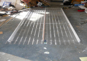
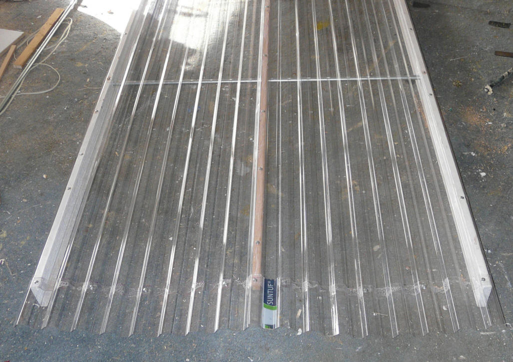
The glazing panel before the rigid foam board
end panels are applied. |
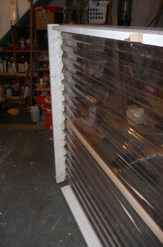
Showing the two edge 1 by 4's, the center
glazing splice strip, and the foamed in place
end panel of insulation board. |
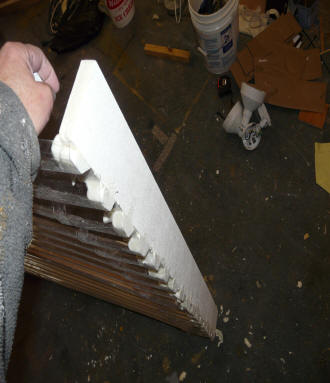
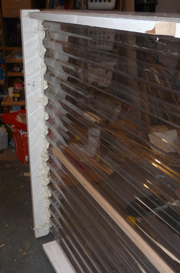
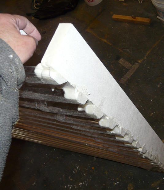
The insulating panels on the ends of the
collector. Bonded to the collector with
polyurethane foam (Great Stuff). |
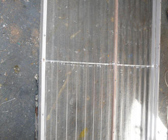
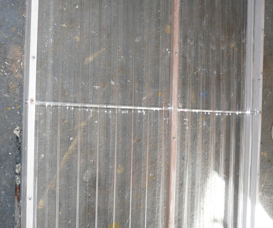
Shows one of the two EMT conduits going
across the collector to support the glazing and
to keep it from flopping around in the wind.
The EMT is installed through holes in the 1 by 4
drilled such that the EMT is in contact with the
bottom of the SunTuf corrugations. |
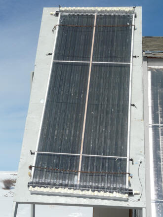
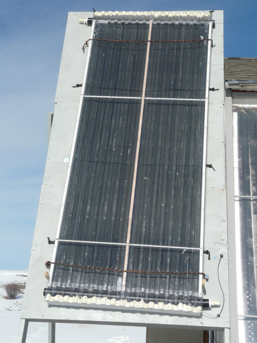
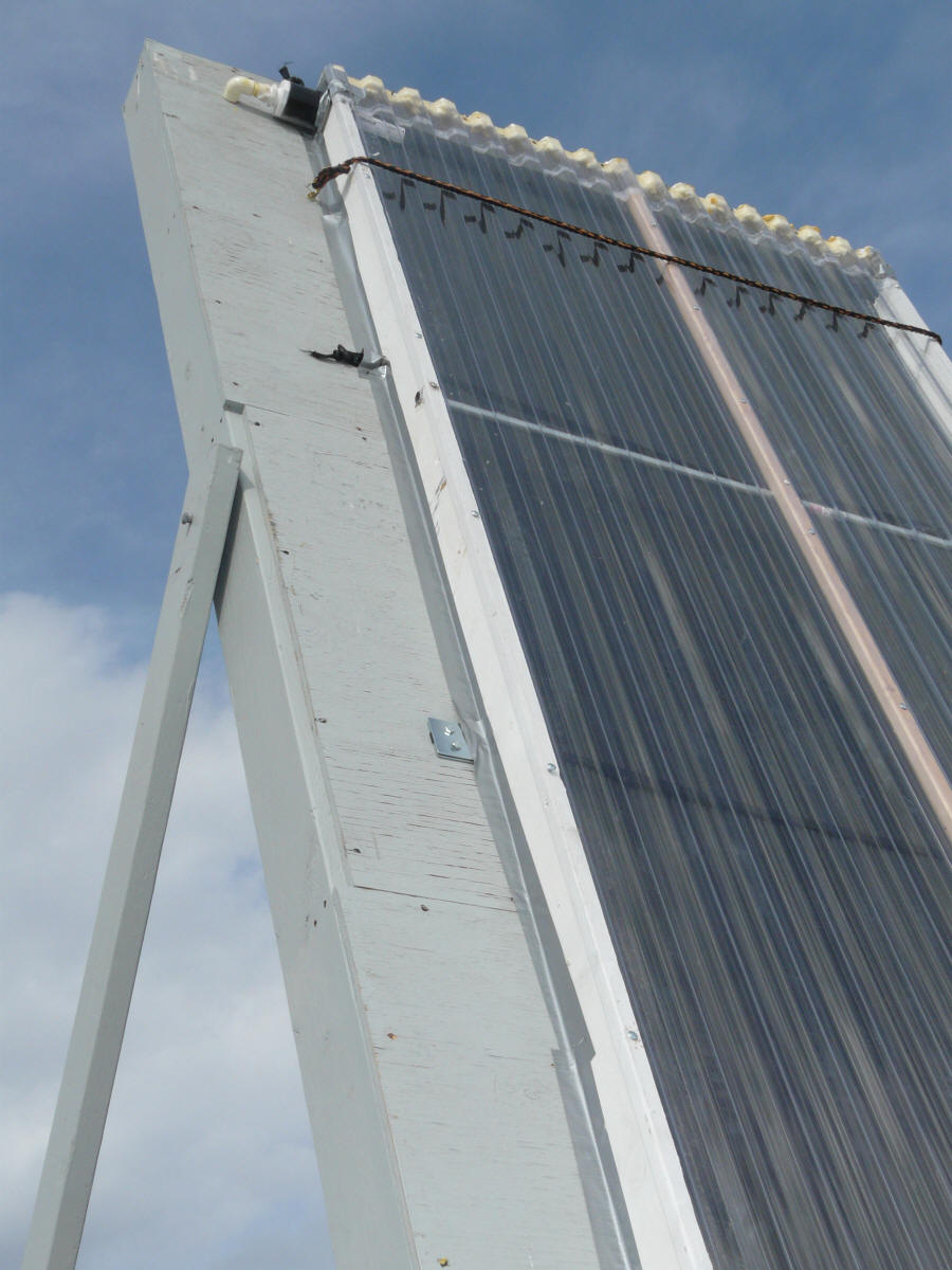
The glazing in place on the collector.
The orange and black polypropylene ropes
hold it down to the collector. |

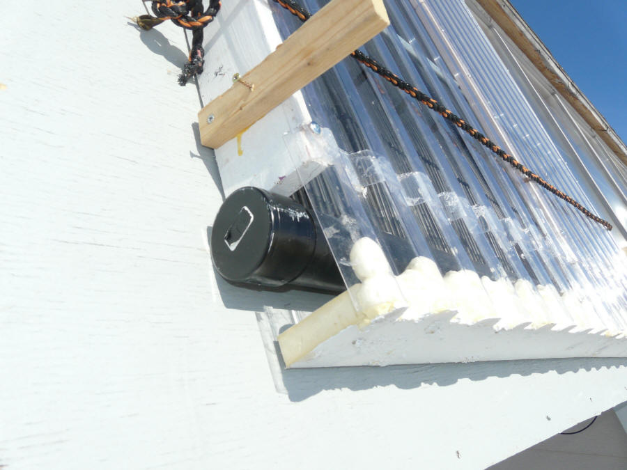
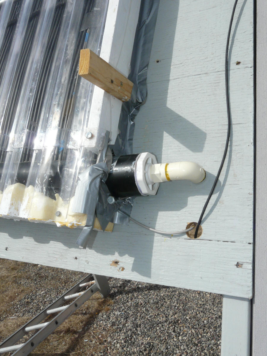
The glazing assembly weight is supported by the lower
manifold as shown above.
The short unpainted wood piece is a handle
to maneuver the glazing into place -- can be
removed once the glazing is positioned.
The spaces around the manifold allow some
air to flow under the glazing for
stagnation ventilation.
The short section of SunTuf added to the bottom
of the glazing is used because an earlier
version of the glazing was shorter, and I did
not want to buy new longer pieces of SunTuf -- on
a final version of the collector, the glazing
would run full length. |
The air velocity through the openings near each manifold was about 200 fpm --
in at the bottom and out at the top. If the area is about 4 sq inches,
then the total flow into the bottom of the collector is about (8/144)(200) = 11
cfm. If this air comes in at 40F and leaves at 110F, then its carrying
away about (11 cf/min)(60 min/hr)(110F-40F)(0.061 lb/cf)(0.024 BTU/lb-F) = 670
BTU/hr -- of the order of 1/10th of the collector heat output per hour.
This glazing scheme is simple and easy to build. It was designed mostly
just to test whether having the glazing significantly improves the collector
performance. One problem that I see is that the insulating boards that
close off the ends might be subject to damage is displacement by snow. There are probably glazing designs that would look and
perform better -- any ideas?
Performance
The plot below shows one sample day of testing with the glazing described
above.
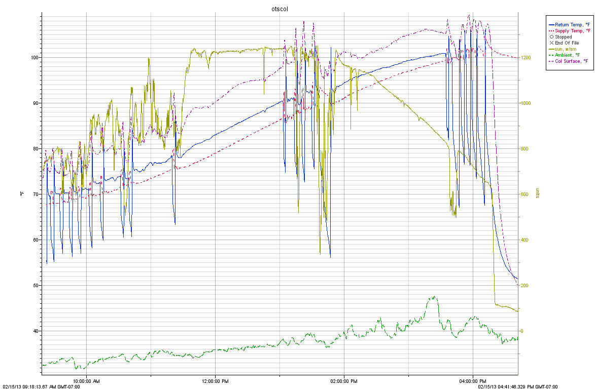
In this plot:
- Red is collector supply temperature (F) -- from the
tank
- Solid Blue is collector return temperature (F) -- back
to tank
- Solid Green/Yellow is solar intensity (w/sm)
- Dash Purple is collector surface temperature
- Dash Green is ambient temperature.
If you look at the sun curve, it may seem strange that there are sun levels
that go above 1200 watt/sm, in that 1000 watts/sm is often quoted for full sun.
The main reason for this is that the pyranometer is mounted in the plane of the
glazing (so that it will receive the same radiation the the collector receives),
and in this position it gets both direct sun and sun reflected of the snow field
in front of the collector. Pyranometers at weather stations are mounted
horizontally, and do not get the snow or ground reflections.
The points that define the efficiency curve for the for the glazed panel in
the plot below are taken from several days of testing similar to the one above.
The points to estimate efficiency were taken at points where the collector was
experiencing steady conditions.
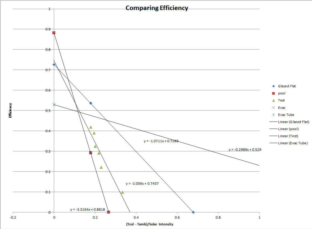
The plot above is a comparison of the efficiency of:
- Red Squares -- unglazed pool heating collector,
- Blue Diamonds -- a high quality, copper fin and riser, commercial glazed
flat plate
- Green Triangles -- our glazed pool heating collector with some air
leakage to reduce stagnation temperatures.
- Purple X's -- Evacuated tube collector
The horizontal axis parameter is the temperature difference between the
collector absorber and the ambient temperature divided by the solar intensity.
Basically, as it gets colder and/or the sun gets less intense, the efficiency of
all these collectors drop -- but some drop faster than others.
The curves for the unglazed collector, commercial flat plate collector, and
evac tube collector are taken from the
SRCC
certification data. The curve for our glazed pool collector is
developed from my testing. So, given that I don't know the details of the
SRCC test procedure, there may be some differences just due to differences in
methods.
As expected, over most of the range of sun and temperatures of interest for
water heating, the glazed pool heating collector is better than the pool
heating collector, but not as good as the commercial flat plate. The
reasons its not as good as the flat plate could be: 1) the intentional air
leakage under the glazing reduces its efficiency, 2) the absorber construction
of the pool heating collector is probably not be as efficient as the copper based
collector, 3) differences in the procedure for determining efficiency between
the SRCC methods and my testing.
The table below shows the same data related to common operating conditions
for solar water heating. The points in the table assume that the solar
water tank temperature is 105F and the average absorber temperature is 110F.
|
Weather |
Ambient |
Sun |
Parm |
Unglazed Pool |
Our Glazed
Pool |
Glazed Flat
Plate |
Evac Tube |
| Condition |
Temp (F) |
BTU/sf-h |
Tt-Tc/Isun |
BTU/sf |
BTU/$ |
BTU/sf |
BTU/$ |
BTU/sf |
BTU/$ |
BTU/sf |
BTU/$ |
| |
|
|
|
|
|
|
|
|
|
|
|
| 70F -- Full
Sun |
70 |
300 |
0.133 |
131.9 |
38.5 |
142.9 |
26.3 |
175.0 |
5.6 |
146.7 |
4.8 |
| 50F -- Full
Sun |
50 |
300 |
0.200 |
65.6 |
19.1 |
102.8 |
18.9 |
153.6 |
4.9 |
140.8 |
4.6 |
| 30F -- Full
Sun |
30 |
300 |
0.267 |
0.0 |
0.0 |
62.6 |
11.5 |
132.2 |
4.3 |
134.8 |
4.4 |
| |
|
|
|
|
|
|
|
|
|
|
|
| 70F -- Part
Sun |
70 |
210 |
0.190 |
52.5 |
15.3 |
75.9 |
14.0 |
109.7 |
3.5 |
99.1 |
3.3 |
| 50F -- Part
Sun |
50 |
210 |
0.286 |
0.0 |
0.0 |
35.8 |
6.6 |
88.3 |
2.8 |
93.2 |
3.1 |
| 30F -- Part
Sun |
30 |
210 |
0.381 |
0.0 |
0.0 |
0.0 |
0.0 |
66.8 |
2.2 |
87.2 |
2.9 |
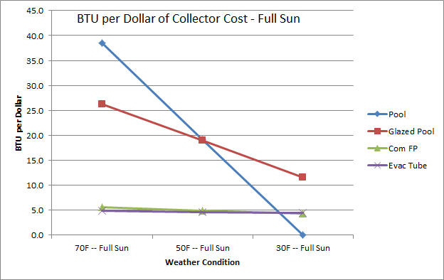
I've colored the text green for the winning collector on heat output per sqft
of panel.
I've colored the text purple for the winning collector on BTU pers sqft per
dollar of collector cost -- probably the thing you are most interested in.
The BTU produced per dollar of collector cost are an indicator of the cost
effectiveness of the collector -- the more BTU per dollar, the better.
Every type of collector wins at something!
Some messages from this:
- For warm, sunny conditions, the plain old pool heating collector is the
clear winner on BTU delivered per dollar spent.
Bear in mind that many places are warm and sunny for three seasons of the
year.
- For cold and part sunny conditions, both the glazed and unglazed pool
heating collectors provide zero heat. The flat plate and evac tube
collectors both provide useable heat with the evac tube beating out the flat
plate by a little in the most cold and least sunny condition.
- The glazed pool heating collector stakes out a good amount of territory
in full sun with moderate and cold temperature as well as the part sun with
warm to moderate temperatures. Basically, it provides good heat output
in all full sun conditions, and useful output with part sun in warm to
moderate ambient temperatures, but nothing when when the sun is its cold
combined with low sun.
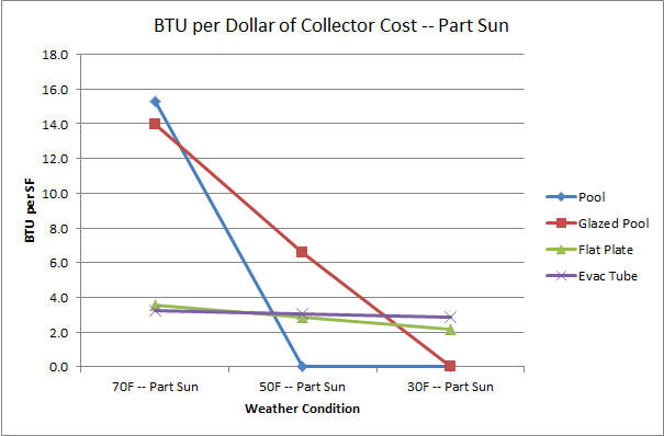
Here is yet another way to look at the same data:
It would be nice to do an actual simulation of yearly energy dollar saved for
all the collectors in a few climates. Anyone want to take this on?-- would
make a great high school or university project.
It seems to me that for most of the conditions on the chart, the glazed pool
heating collector beats the two commercial collectors on heat output per dollar of
collector cost by a factor 3 to 5.
An observation: A lot of people think that the climate they live
in is a lot colder than it really is -- don't trust your gut on this, go to a
site like WeatherSpark.com and actually look at what your average daily high
temperatures are. I am in cold Montana that once is a while gets below
-30F at night, but we no months where the average daily high temperature is not
above freezing. Remember, you do the most solar collecting near the daily
high temperature.
Sealed Glazing
I sealed up the openings that were allowing some air to flow under the
glazing with duct tape. Very ugly, but I think that it is pretty effective
from a selaing point of view.
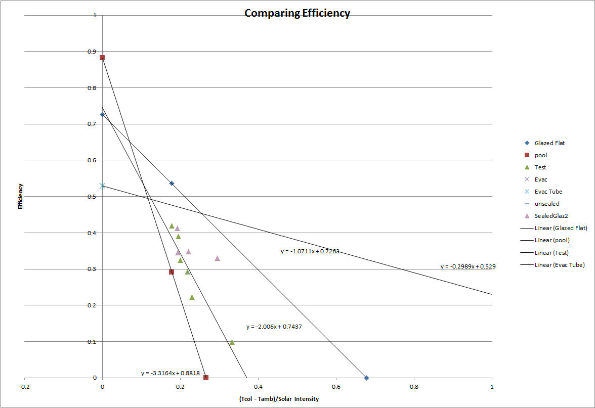
This is the same plot as above with some points added for the one day of
sealed glazing tests.
Purple Triangles -- The sealed glazing
All the rest of the data is the same as the plot above.
So, generally the sealed glazing points lie on the good (more efficient) side
of the the line for the glazed (but not sealed) collector. The gain for
sealing the glazing averages about a 6% increase in efficiency, which is good
for about a 20% increase in heat output for this area of the efficiency curve.
A 20% gain does seem worthwhile, but the downside is that some form of
automated opening vent would likely be required to keep the collector from being
damaged in a stagnation event.
I'm going to leave the collector sealed and see what the collector surface
temperatures run on warmer days.
Update: March 21, 2013: We had a part sunny day today with a gusty wind at about 10 mph -- ambient temperature about 30F. I noticed that the sealed collector was running and making some hot water. I think that in these windy conditions, the unsealed and certainly the unglazed collector would not have gotten warm enough to turn the pump on. So, better wind protection for the collector with the sealing is something to think about in places where some wind is common.
I'd appreciate any thoughts, ideas, comments, questions -- please
use this page for comments...
Gary March 16, 2013