
Search
The Renewable Energy site for Do-It-Yourselfers
Drainback Test on Serpentine
Collector
The easiest way to layout the PEX
collector is to use a serpentine pattern of PEX pipe starting from the top and
extending to the bottom of the collector. Each straight
run of the serpentine pipe layout is sloped slightly down to encourage water to
drain completely from the collector when the pump stops. The collector is
protected from damage that would result from water freezing in the collector by
making sure that it always drains when the pump is not running.
I was a bit concerned that the
drainback process might not be reliable enough for a serpentine collector to
insure a complete drainback in all cases. In use of the prototype over a
couple months, I did not encounter any failures of the water to drain back into
the tank, but I was still concerned that the drain back might not be complete
under some circumstances. I did the test described below so that I could
actually observe the water draining back from the collector and see how robust
and repeatable the drainback process is and to observe what happens when
collector tilt and/or slope are changed in ways that might interfere with
reliable drainback.
I built a section of serpentine
collector using transparent vinyl tubing so that I could actually see the fluid
draining. The pictures below show the setup and show the drain back
process.
Setup
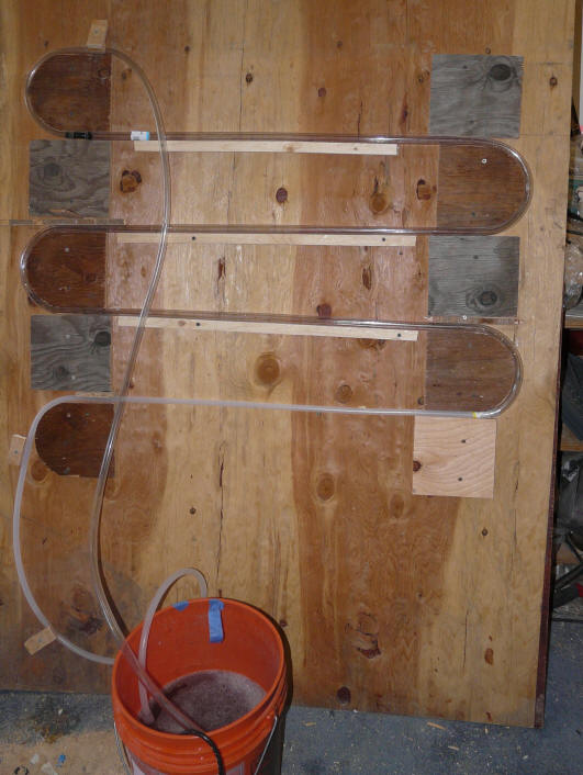
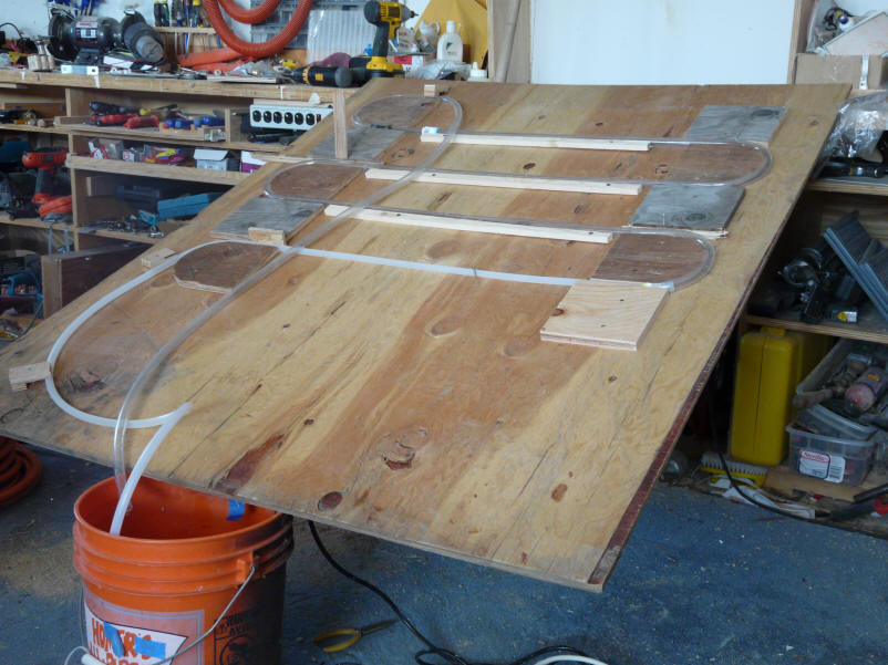
The picture below shows the setup.
The water was pumped from the orange bucket to the bottom of the serpentine
collector tubing. The line from the top of the serpentine collector drains
water back to the bucket -- this line must terminate above the water line in the
bucket.
Some ink was used in the water to
make it a little more visible.
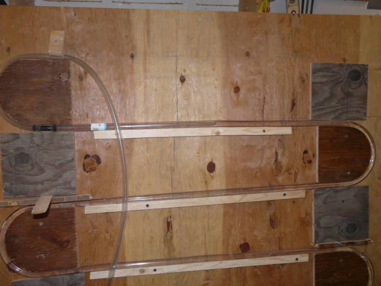
This shows the test setup.
Water is pumped from the orange bucket up through the transparent serpentine
tubes, and then drains back to the bucket via the line from the top of the
serpentine tubes. Each of the straight runs is sloped slightly down --
about 0.5 inch over the width of the collector.
For most of the tests, a little bit
of detergent was added to the water to reduce the surface tension and
(hopefully) improve the drainback. The amount used was about one drop of
dish washing detergent in the full bucket of water.
Normal Drainback
When the pump is stopped, the drain
back process starts with air advancing up the drain tube that goes to the top of
the collector. The air-water interface advances up the drain tube, and
then down each of the serpentine runs until it gets to bucket. This
advance of the air-water interface happens fairly rapidly (less than 30 seconds
for the full setup). I repeated the process many times, and it appears to
be very repeatable and robust. In the 2nd phase of the drainback process,
the water that remains after the air-water interface passes drains down along
the bottom of the tube section. The first phase drains most of the water
and proceeds rapidly. The 2nd phase drains the remaining water, and takes
more time. At the end of the 2nd phase, there is very little water left in
the collector.
The air-water interface is visible
progressing along the upper tubing run from left to right. This interface
advances rapidly down the tubing. Most of the water drains during this
phase. The water that remains after the air - water interface passes
drains more drains more slowly.
Adverse Slope Test
I did several tests in which the one
edge of the bottom of the collector was propped up such that some of the lines
did not have a down slope, or even had an up slope. I don't see any reason
to subject your collector to this kind of abuse, but I just wanted to see how
sensitive the drain back process is to not having a good slope.
With the collector adjusted to make
half of the straight runs level rather than down slopping, the first part of the
drain back process (the advance of the air-water interface) was essentially
unchanged, and this phase drained most of the water out of the tubing. The
2nd part of the drain back process in which the remaining water drains out
resulted in some small pockets of water left in the tubing at the end of the
straight runs (see pictures). These remaining water deposits were small
and in no case blocked the full diameter of the tubing.
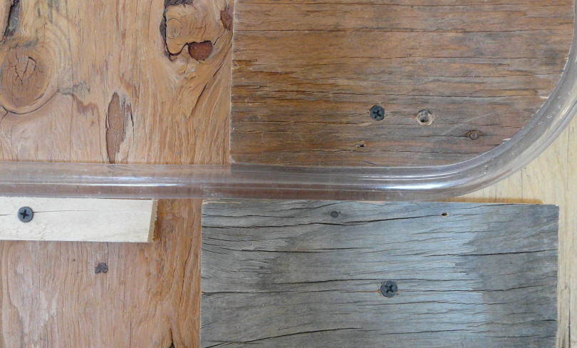
Its hard to see in the picture, but
there is just a bit of water left in the tube at the start of this straight run
that has no down slope.
It would not (I think) be enough to
cause any sort of freezing problem.
I did some more runs in which half of
the straight runs actually slopped upward. These actually drained
surprisingly well. The first phase was pretty much unchanged. The
air-water interface did not seem to mind advancing slightly uphill at all.
The 2nd phase resulted in larger collections of water at the beginning of the
upward slopping tubing sections. In some cases, there was enough water to
fill the full diameter of the tube for short sections (see picture below).
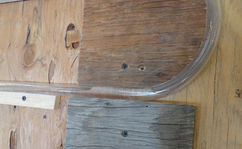
This shows the deposit of water
remaining at the start of an upward slopping tubing run after both phase 1 and
phase 2 had completed. If this were to freeze, I doubt that it would cause
an problems, as there is room from expansion of the ice into the air pockets in
both directions.
While its reassuring that the
collector still drains pretty well even without the down slope, I would strongly
encourage you to make sure that the collector is built with a down slope on
every single run.
Low Tilt Test
I also tried a test in which the tilt
of the collector was reduced to about 20 degrees to see if this impacted the
drainback process.
The low tilt collector still drained
reliably, but took a little longer.
This shows the setup for the shallow
tilt drain back test. Although the drain back time was a little
longer, the process occurred in the same way as for the higher tilt cases, and
appeared to be equally predictable.
Gary August 31, 2008