Search
The Renewable Energy site for Do-It-Yourselfers
Window Screen For
Solar Collector Absorber
|
This is a small test of two types of
ordinary insect window screen used as the absorber in a solar collector.
Motivation for the test is just to understand better how much the screen absorbs
and let through, and to think about ways to improve the performance.
Two layers of window screen
appear to do well as the absorber for solar air heating collector.
Here is
one example... In the testing that
Scott
and I have done to date, the two layers of screen have done about as well or better
than other more complex absorber configurations tried so far.
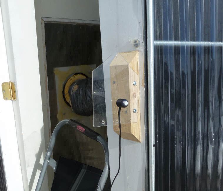
Typically in these collectors
that use screen for the absorber, the intake air is introduced across the bottom of the
collector on the glazing (sun) side of the screen absorber. The
outlet vent is at the top of the collector at the back of the collector
box such that the air has to flow through the absorber from the glazing
side to the back side to get out. The thinking is that the sun
heats the black screen, and the air flowing through the screen picks up
the heat. The screen is thought to work well because it
provides a lot of surface area for heat absorption, and because the
screen
has a small amount of air resistance that helps to spread the air evenly
over the full absorber. |
|
A somewhat different alternative on
how the screen works was proposed by Laren on the
SimplySolar Yahoo discussion group last week. This is that the screen
has so much open area that 2 layers do not absorb a major part of the solar, and
that a lot of the light gets through the screen and is absorbed instead by the
back wall of the collector. The screen absorbs some light, but also acts
as a barrier to keep the heated air behind the screen layers from moving forward
and contacting the glazing -- which would result in high heat loss. It
seems plausible to me that this is at least part of what is going on, and one
clue to finding out which model is right is to determine how much sun the screen
actually absorbs.
Pyranometer Absorption Test
In order to try to get a better idea how much
of the solar is absorbed coming through the screen, vs at the back of the
collector box, I did the small experiment described below. Basically, I
just measure sun intensity with a pyranometer first without any screen, and then
with 1, 2, and 3 layers of screen in front of the pyranometer. The pyranometer
reading should drop by an amount roughly equal to the amount of solar absorbed
by the screen(s).
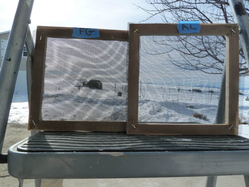
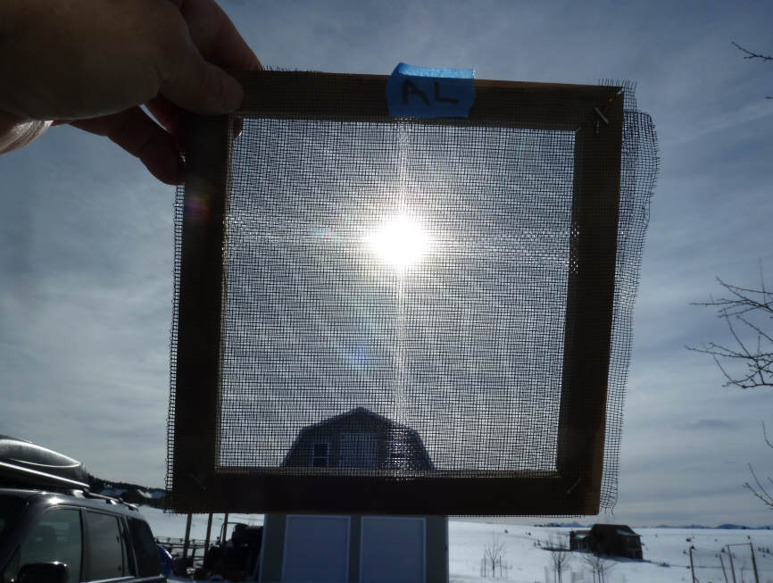
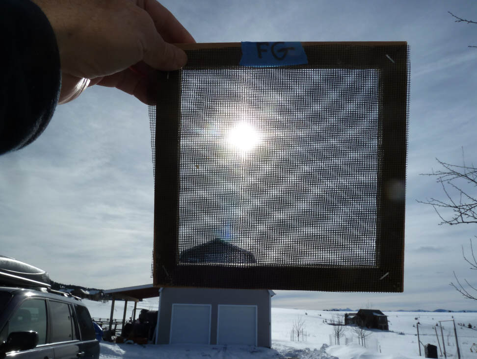
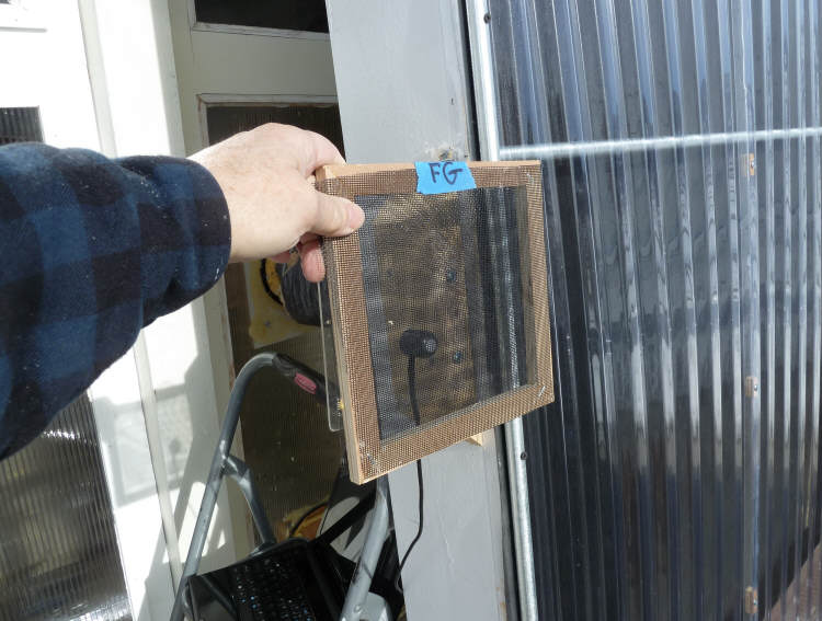
I tried fiberglass and aluminum
screen -- both black.
The wire diameter on the FG screen
was 0.008 inch, and the thickness of the screen is 0.0125 inch.
The wire diameter on the alum screen
is 0.009 inch, and the thickness of the screen is 0.021 inch.
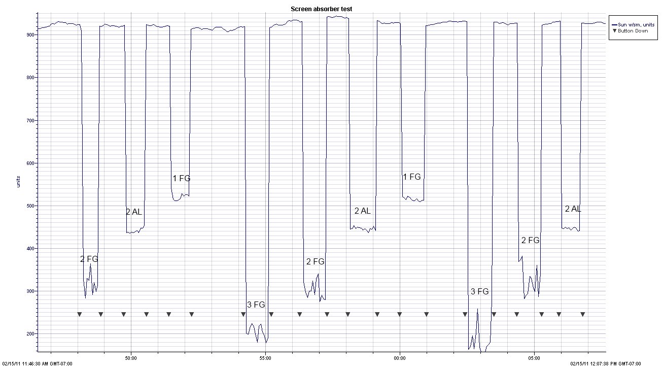
The table below shows the sun
intensity readings through 1, 2, and 3 layers of fiberglass screen, and through
2 layers of black aluminum screen.
The percent of light absorbed is also
shown.
The logger plot that the numbers
numbers in the table were derived from is shown at the end of the page.
Three runs were done with 2 layers of FG screen and 2 layers of AL screen,
and 2 runs with 1 layer of FG and with 3 layers of FG. The
fraction of sun light getting through is calculated separately for each run
using the average of the full sun values just before and after the screen is
placed over the pyranometer. The full sun value is divided into the
reading with the screen in place to estimate the fraction of light that the is
getting through the screen. Then the absorption readings for the runs are
averaged to get the number in the table. As the plot show, the variation
was pretty small. It was a good sun day -- some clouds away from the sun,
but none in the vicinity of the sun. It was windy and about 46F.
I held the screen about 3 inches in
front of the pyranometer head by hand. The idea of holding the screen by hand is that
it makes the screen shadow pattern on the pyranometer head move around --so, if
the reading changes as the shadow pattern moves, holding the screen by hand
should help to average any variation out
-- doing 3 runs also helps average things. The readings from the different
runs agreed well, so I don't think that the shadow pattern is an issue.
| |
Fraction of sun getting through to pyranometer |
Fraction of sun absorbed by the screen(s) |
|
1 layer FG screen |
0.56 |
0.44 |
|
2 layers FG screen |
0.34 |
0.66 |
|
3 layers FG screen |
0.21 |
0.79 |
| |
|
|
|
2 layers AL screen |
0.48 |
0.52 |
So, it looks like 2 layers of the FG
screen absorbs about 66% and 2 layers of the Al screen absorb about 52%.
Tentative conclusions/questions:
- A fair bit of sun does get
through the 2 layers of screen, and the back wall of the collector does
apparently play a significant role in absorbing the sun.
- At least for these two samples
of screen, the fiberglass screen absorbs somewhat more sun than the Aluminum
screen.
- Each layer of screen added
absorbs less light - basically, if you start with 100 units of light, the
first screen absorbs 44 units, adding the 2nd screen absorbs 22 more units,
and adding the 3rd screen absorbs 13 more units. This is what you
would expect as the front screens partially shade the back screens.
So, each layers is less effective at absorbing but does still absorb some
more light, and also provides more heat transfer area.
- You have to wonder if adding
the 3rd layer of screen to move more of the absorption up to the screen
plane would not be better? (see note 1 below) .
- If the back wall of the
collector is doing a significant fraction of the absorbing, maybe some
changes could be made to improve its absorbing characteristics -- like more
surface area?
- The back wall of the collector
is going to be running hot. It seems like it wants to be well
insulated to reduce heat loss, and should be isolated from high thermal mass
items (like the back of the collector box).
- If the back wall of the
collector were 100% reflective, and the screen had the same absorption
characteristics on the way out, then 2 layers of FG screen would let out
(0.34)(0.34) = 12% of the incident sun light, and 3 layers with a reflective
back would let out 4% of the sun light.
With a 90% absorption collector
back, 2 layers would let out (0.34)(0.1)(0.34) = 1.1% of
the incident sunlight, and 3 layers with a black back would let out
0.4%.
Anyone see anything wrong with the
way the way all this was done? Or, with the conclusions?
Anyone have any absorber improvement
ideas?
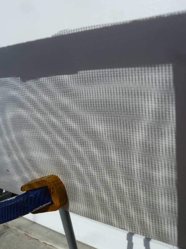
Screen Shadow Patterns
The pictures below show the shadow
pattern on a white board for various screen configurations.
Three layers of fiberglass screen:
 |

Shadows from 3 layers of FG screen. |
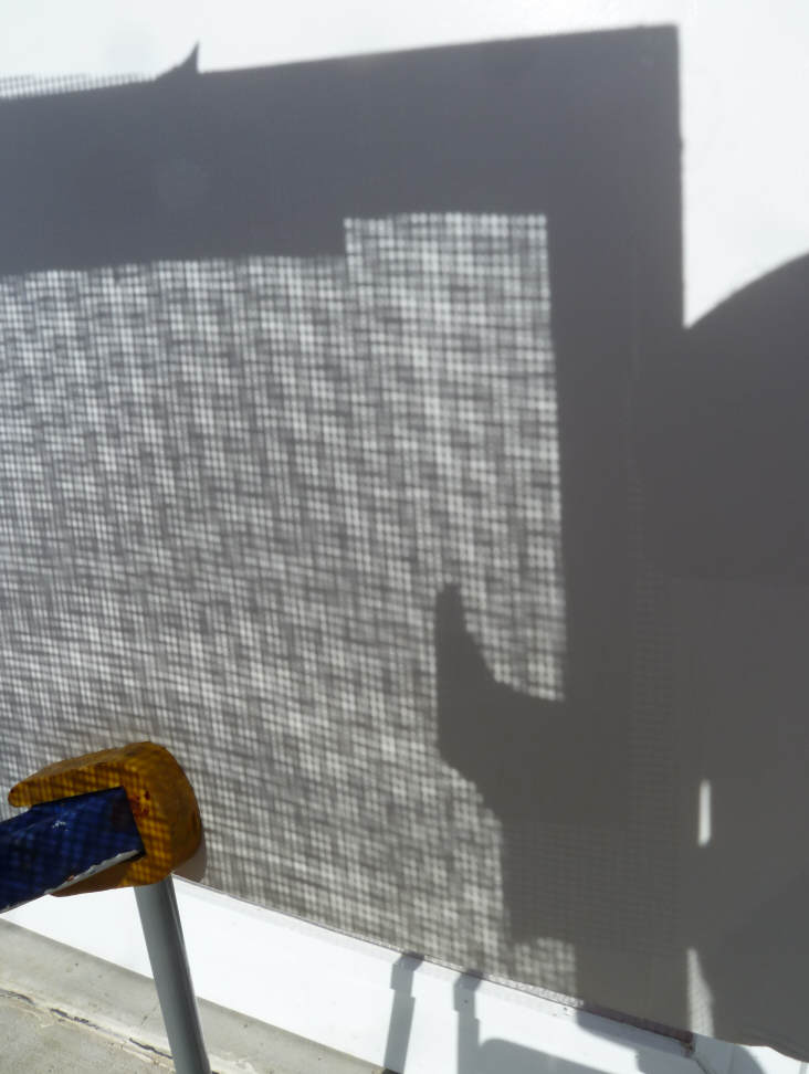
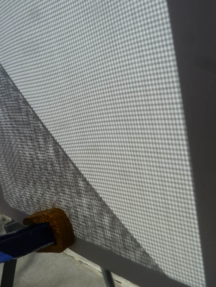
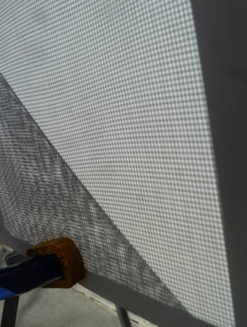
Two Layers of FG screen:
 |
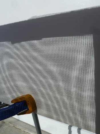
Shadow from 2 layers of FG screen. |
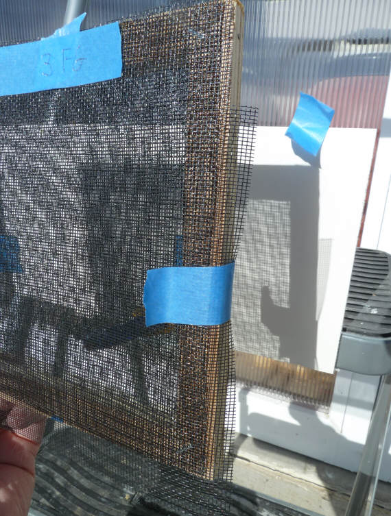
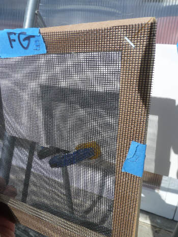
One and three layers of FG screen:
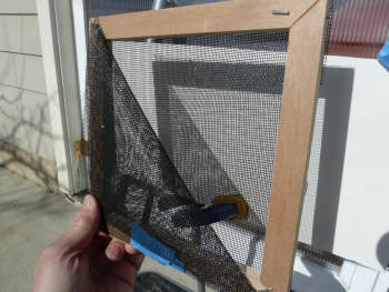
This is the frame that holds the 2 layers of FG
screen with one layer folded back so the left half is
3 layers of screen and the right half is one layer. |
One layer shadows on right and 3 layers shadows on left. |
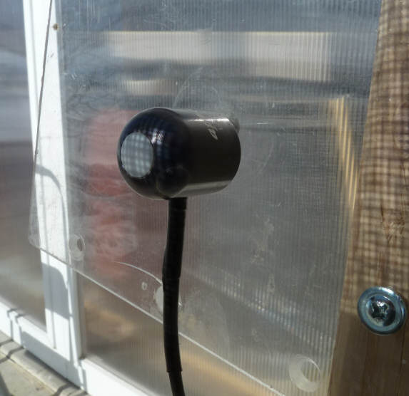
This is the shadow pattern on the
pyranometer head for 3 layers of FG screen.
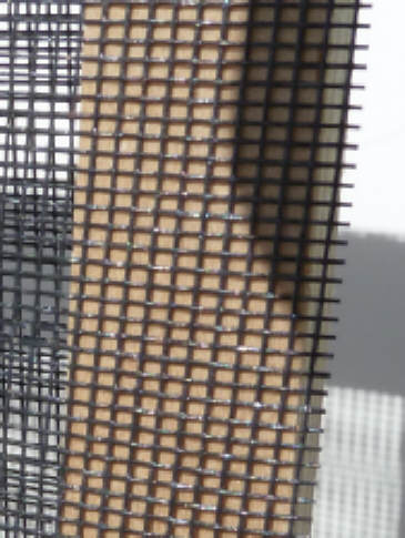
Fiberglass screen close-up:
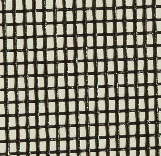
Lots of open area.
Based on a blow up of the picture
above, I'd estimate the open area at roughly 62% .
The pyranometer says that 56% of the
light gets through one layer of screen, so the percentage of absorbed light
appears to be a bit higher than the percentage of screen open area.
Logger Plot
The logger record of the measurements
is shown below.
Note (1) -- I did try 1 layer vs 2 layers vs
3 layers on my
thermosyphon collector, and in this case 2 and 3 layers about tied and both
better than 1 layer. But, on a fan forced collector 3 may be better than
2?
Gary Feb 15, 2011