Search
The Renewable Energy site for Do-It-Yourselfers
Sun Simulator for Solar Thermal
Collector Testing
|
This page details a sun simulator that I use for testing solar
thermal collector designs. The simulator provides light levels up
to one full sun for a collector up to about 2 ft wide by 3 ft high.
The simulator allows collector design changes to be evaluated under
consistent conditions, and also allows easier instrumentation of the
collector to get a better idea what's going on in the collector in terms
of temperature distributions and flow patterns -- this can point the way
to improvements in the design.
There are lots of sun simulators out there. What I was aiming
for in this one was a simulator that was good enough to do real
engineering work on collectors with a budget of a few hundred dollars.
The final word is not in yet on whether this simulator get there, but
things are looking good.
This page describes the "final" design -- there is some material on
the earlier trials and tribulations here...
I want to thank all the folks who sent in suggestions and comments --
many of those suggestions were helpful in getting to the current design.
|
|
Overview
The simulator uses six 400 watt metal halide lamps as the light source.
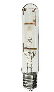 This
is the spec
for the lamp...
From 1000bulbs
...
(I don't usually recommend companies, but I have to mention that 1000bulbs.com
has been really helpful through two orders of lamps and ballasts and odds and
ends -- real humans who know what their products plus good prices and fast
shipping). The lamp is 1.8 inches in diameter by 9.75 inches long -- 10 bucks a
lamp. The lamps produce light by maintaining an arc through the arc tube that
you can see inside the outer glass envelope. The arc length is about 1.5
inches. Each lamp has a ballast that provides the right arc starting voltages
and maintains the arc current at the right level once the arc is established.
The arc operates at about 135 volts once established.
This
is the spec
for the lamp...
From 1000bulbs
...
(I don't usually recommend companies, but I have to mention that 1000bulbs.com
has been really helpful through two orders of lamps and ballasts and odds and
ends -- real humans who know what their products plus good prices and fast
shipping). The lamp is 1.8 inches in diameter by 9.75 inches long -- 10 bucks a
lamp. The lamps produce light by maintaining an arc through the arc tube that
you can see inside the outer glass envelope. The arc length is about 1.5
inches. Each lamp has a ballast that provides the right arc starting voltages
and maintains the arc current at the right level once the arc is established.
The arc operates at about 135 volts once established.
The magnetic ballasts I used are essentially a
transformer and a capacitor.
To save money, I bought ballast "kits" which have the ballast transformer and
capacitor, but no case. There are more sophisticated digital ballasts, but
for this project, the cheap magnetic ballasts appear to work fine.
The six lamps are mounted in an array that is 2 lamps wide and three lamps tall.
Each horizontal pair of lamps gets a shallow parabolic reflector behind it.
The reflector for each pair is 15 inches tall and about 30 inches wide -- so,
the three pairs stacked gives 45 inches high by 30 inches wide.
A "light tunnel" surrounds the array of lamps and reflects light rays that are
headed off for the sides and would not hit the collector back toward the
collector. The light tunnel is 31 inches wide by 47 inches high. The
inside of the tunnel is covered with reflective aluminized Mylar.
The basic idea is that the parabolic reflectors get all the light from about the
back 220 degrees of the lamp and reflect it forward, but not necessarily right
at the target. The idea of the tunnel is that light that would miss the
collector gets reflected by the tunnel back toward the collector.
This arrangement achieves full sun light levels about 13 inches from the mouth
of the tunnel. The light levels drop off as the collector is moved further
away. I've not had a chance to do a full survey of the light levels over
the full surface of the collector, but just moving the meter around appears to
indicate a fairly uniform distribution.
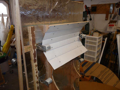
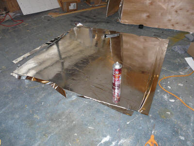
The reflectors were made from 0.018 thick sheet aluminum to which aluminized
Mylar was attached.
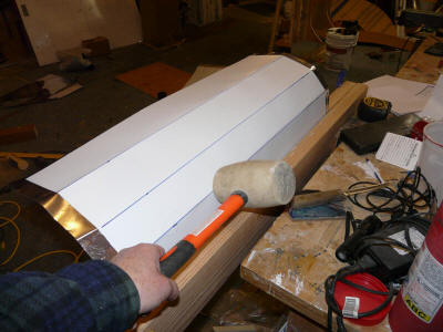
Forming the segmented parabolic reflector. |
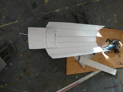
The reflector after rough forming. |
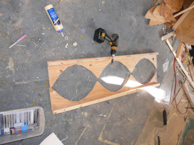
The three reflectors are supported by these two template
boards, which get mounted to the light backboard. |
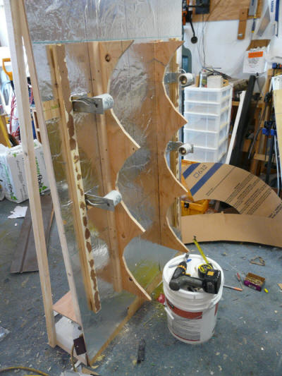
Reflector supports mounted to the light backboard. |
Reflector mounted to the form, which enforces the
parabolic shape. |
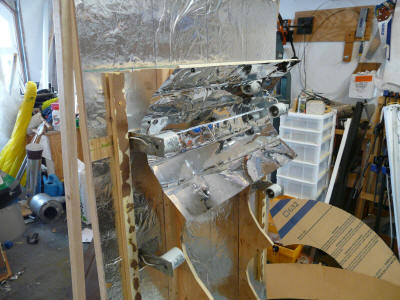
With the aluminize Mylar applied. |

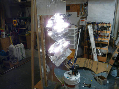
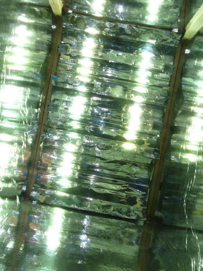
This shows the light warming up. You can see the lamp's
reflection in each segment of the parabolic reflector -- I'm
taking this to mean that the shape of the reflector is good. |
Testing with two of the reflectors done.
|
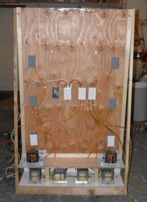
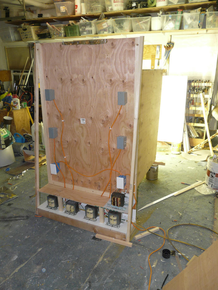
The ballasts mounted on the back of the light board.
The 6 junction boxes on the edges go to the 6 lamps.
The junction boxes in the middle are switches to
turn the lamps and the light tunnel ventilation on and off.
I had to split the 6 lamps onto 2 circuits because all 6 on one
circuit would exceed the breaker rating.
|
|
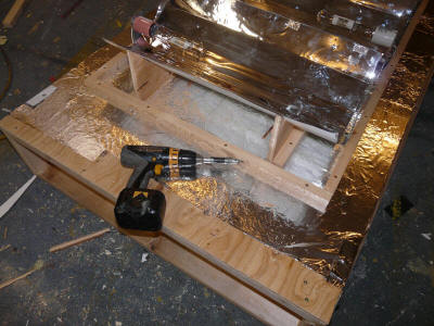
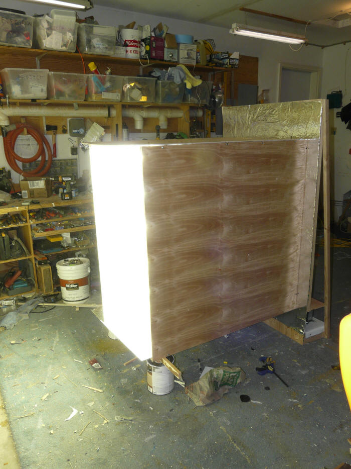
Shows the perimeter frame around the reflectors that
will support the light tunnel. |
The light tunnel sides are light weight quarter inch plywood
with 1 mil aluminized mylar help in place by 3M 77. |

The light tunnel in place.
The paint can supports will become forward legs. |

Another angle. |
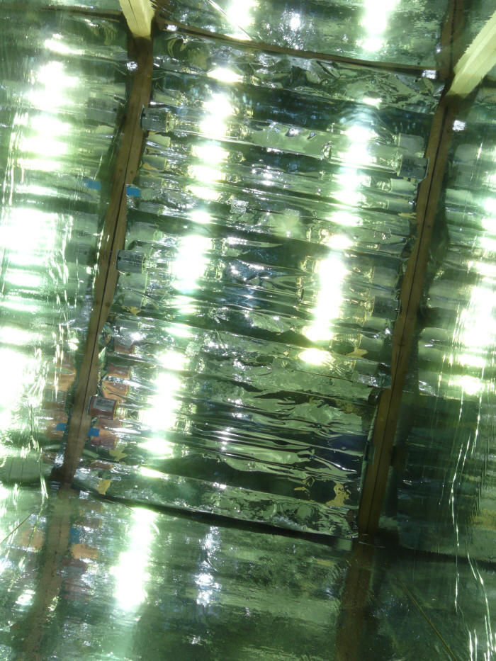
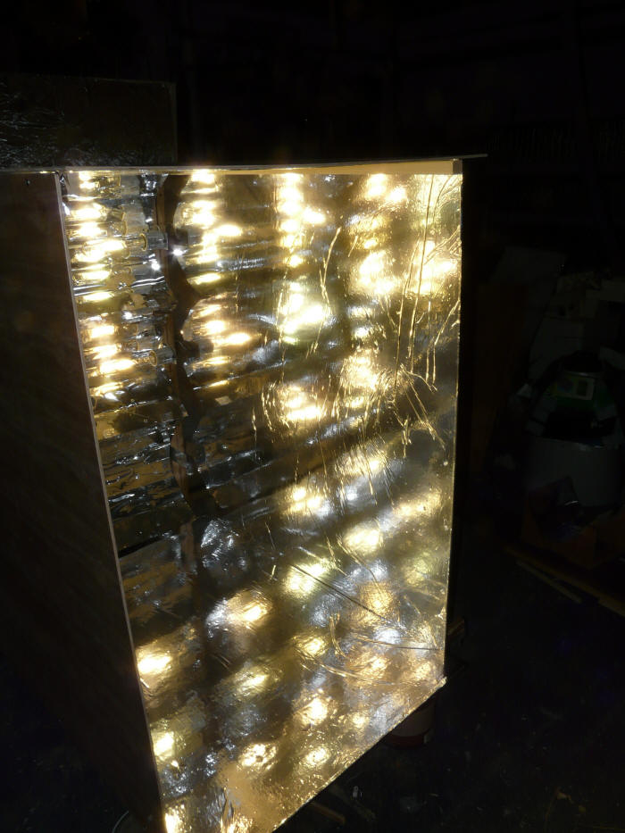
View into the business end.
(the lower right lamp is on back order) |

A bit more from the side. Note all the distinct lamp
reflections on the light tunnel side panel. |
Just a quick check on performance shows light levels around 100K lux (full sun)
at 16 inches from the end of the light tunnel. This is just OK as it
leaves just enough room to play with and take measurements on the collector
during testing.
The temperatures around the reflectors are surprisingly low -- no problem to
touch anything and leave your hand on it. I left ventilation space behind
the collectors, but need to add some ventilation and a fan for the front side
and light tunnel. Standing in front of the light tunnel fells a lot like
standing in the sun on a sunny day.
Collector and Stand
The first collector is 2 ft wide by 3 ft high and 6 inches deep. It
will be used to look at variations in solar air heating collector designs.
The collector is made so that both the front (glazed surface) and the back
(insulated surface) can be pulled off easily. This will allow quick
changes to the collector internals, and also allows glazing that is IR
transparent to be substituted for the regular glazing so that the IR camera can
be used to take pictures through the glazing of the absorber.
The collector is set up such that it can be rotated quickly to the side to
take the IR pictures.
The stand is just a sort of sled that supports the collector at the right
height and can be easily moved back and forth to get different sun levels.
<pic>
Cost
I've not really kept a careful accounting, but this is pretty close:
| Item |
Quantity |
Unit Price |
Total Cost |
| 400 watt metal-halide lamps |
6 |
$10 |
$60 |
| Lamp ballasts |
6 |
$40 |
$240 |
| Lamp sockets |
6 |
$3.58 |
$22 |
| Reflector Aluminium |
|
|
$30 |
| Wire -- scrap box |
|
|
$0 |
| Electrical boxes, wirenuts,
wiring supplies... |
|
|
$30 |
| Plywood for lamp board and
light tunnel |
|
|
$55 |
| Framing lumber |
|
|
$10 |
| Mylar reflector film |
|
|
$17 |
| Vent fan for light tunnel
-- scrap box |
|
|
$0 |
| Metal and other supplies
|
|
|
$62 |
| Plywood for collector stand |
|
|
$15 |
| |
|
|
|
| |
|
|
|
| |
|
|
|
| |
|
|
|
| |
|
|
|
| |
|
|
|
| |
|
|
|
| |
|
|
|
| Total |
|
|
$541 |
The cost table does not include money spent on the trial versions.
The cost of the test collector(s) is also not included.