Search
The Renewable Energy site for Do-It-Yourselfers
Test of a
Thermosyphon Solar Water Heating System Using a Collector Made from Copper
Tubing and Aluminum Heat Transfer Fins
Update added April 23...
This is a test of a
thermosyphon solar water heating collector. This collector uses the design
in which horizontal manifolds at the top and bottom of the collector are
connected by multiple vertical riser tubes. Each riser tube has an
aluminum heat transfer fin painted black to absorb the solar radiation and
transfer the heat into the tubes. The collector used for this
test is the first prototype I made of the copper tube, aluminum fin collector
made back in 2008 --
its described in full here...
For thermosyphon
systems, the storage tank that is heated by the collector is placed above the
collector. The collector inlet (on the bottom of the collector) is
connected to the bottom of the storage tank. The collector outlet (on top
of the collector) is feed into the tank hear the top.
As sun heats the
water in the collector, it becomes less dense and rises out the top of the
collector and into the tank. This water is replaced by cold water from the
bottom of the tank flowing into the bottom of the collector. As long as
the sun continues to heat the water in the collector, a circulation loop is
setup in which water flows continuously out the bottom of the tank, through the
collector, and then back into the top of the tank.
When the sun goes
off the collector, the water in the collector cools, and circulation no longer
occurs since the water in the collector is more dense than the tank water and
naturally stays in the collector.
So, in this system,
the circulation is all by natural forces -- no pumps needed. And, the
control is automatic -- no controllers needed.
These systems are
very simple and are widely used in some parts of the world.
I did the test on
this copper/aluminum collector to see how it compared to a similar test done on
a collector that uses PEX tubing and aluminum heat transfer
fins -- described here...
All in all, I would
say that this thermosyphon water heating system performs well. While the
system shown here is just a very crude prototype, I believe that an actual
system could be built that would: 1) cost about $300, 2) perform well, 3)
last a long time, and 4) look nice.
I am puzzled by some
aspects of the performance (see below) -- maybe there is a thermosyphon
knowledgeable person out there who can explain this?
Compared to the
popular batch solar water heating systems, the thermosyphon offers a system that
is nearly as simple and cheap to build, but does not have the larger
temperature drop over night that batch systems experience.
More on
thermosyphon systems here...
Test Setup
This is a very crude thermosyphon
solar water heating system. It was built just to do this one test, so the
construction was for speed -- not for life or looks -- I know its ugly, but it
can be made to look just fine for real applications.
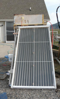
The
collector used is described
in detail here... This is the original prototype of the
copper/aluminum collector built in 2008. It has been sitting in the yard,
pointed south and stagnated since the end of 2008. The wind has dumped it
over on its glazing twice -- careless of me to let this happen. But, the
collector survived all this very well -- its in great shape inside and outside.
The collector is glazed with a single
layer of SunTuf corrugated polycarbonate glazing. I pulled a corner of
this back to install the heat sensor on the absorber, but otherwise the
collector is unchanged from the original prototype.
The collector area is about 32 sqft.
The storage tank is a galvanized
stock tank -- 45 by 21 by 12 inches tall with rounded ends. The tank is
vented to the atmosphere -- ie not pressurized. For this test, the tank holds 40
gallons.
The tank is insulated all the way
around with 2 inch thick (R13) polyiso insulation.
The bottom of the tank is about 6
inches
above the top of the collector.
The outlet from the tank to the
collector inlet makes use of the tank drain fitting, and is near the bottom of the
tank on the east side.
The inlet to the tank from the top of
the collector uses a bulkhead fitting to enter the tank just below the water
line near the top of the tank.
I was not able to completely avoid
bubble traps in the collector plumbing because on this collector the inlet and
outlet come out the back of the collector.
It may be that the these small bubble
traps at the inlet and outlet cause the mysterious "no flow" episodes discussed
below?
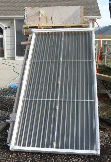
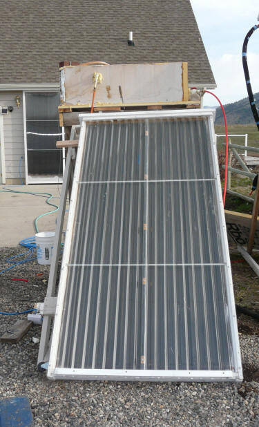
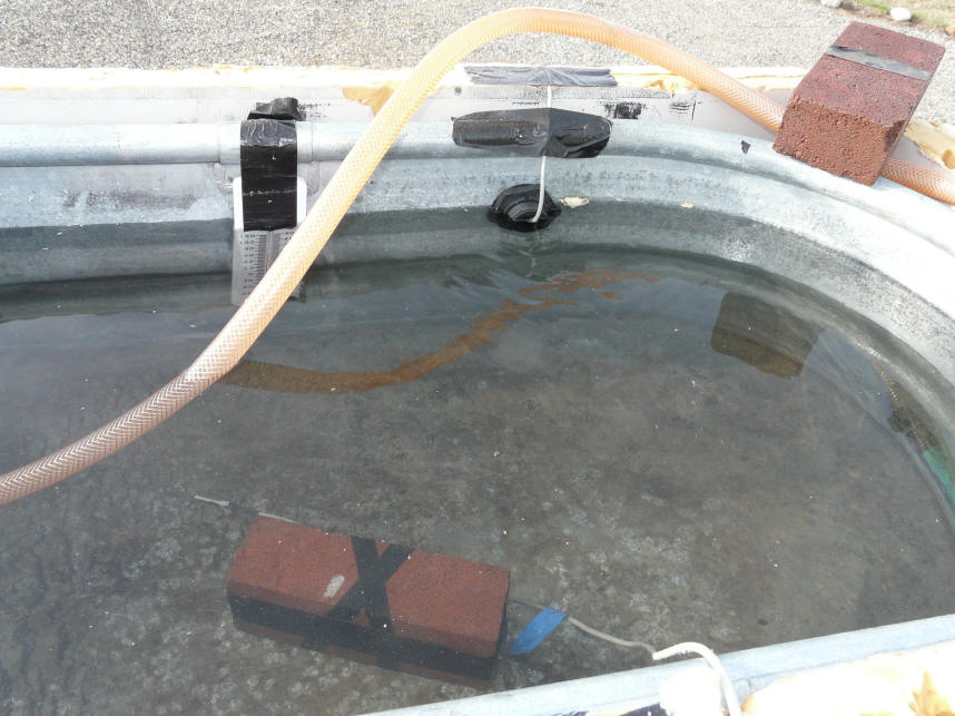
|
The collector and tank. |
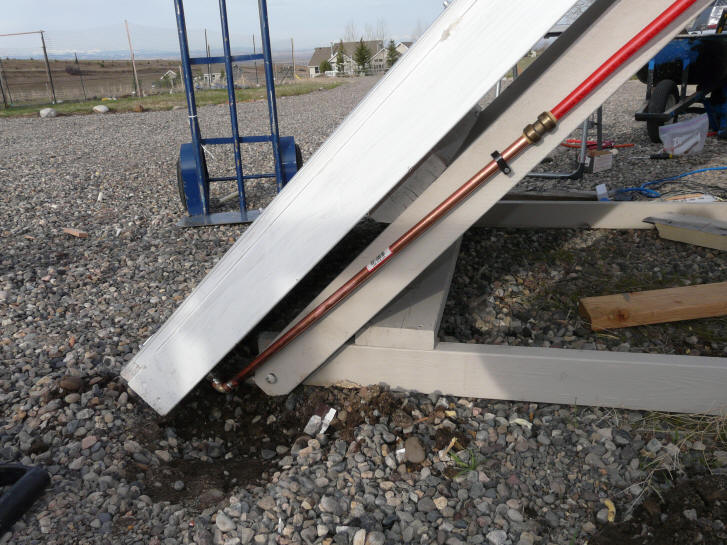
Collector inlet. |

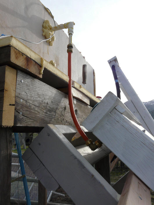
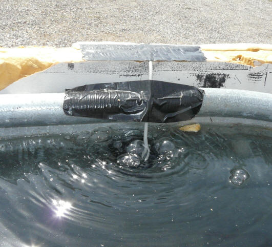
Collector outlet and tank
inlet. |
|
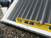
Collector is slightly sloped up
from the inlet side. |
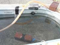
Tank inlet before the tank was
fully filled up. Temp sensor
is pushed into the inlet about 1.5
inches. Mid tank temp sensor
is taped to bricks. |

Big bunch of bubbles coming
up the collector outlet tube.
This would happen only once
in a while. |
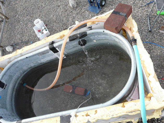
I filled the tank with a garden hose by running water into the tank outlet and
letting the
fill water run through the collector and come into the tank via the tank inlet.
Idea was to get all the air out of the collector, and get the thermosyphon
circuit full of water.
Top black dashed line --
Collector temperature (F)
Red dashed line -- Collector
outlet temperature (F)
Purple line -- Tank temperature
at mid tank (F) -- not that tank was highly stratified, so this is NOT
an average tank temperature
Blue line -- Collector inlet
temperature and bottom of tank temperature (F)
Sickly green line -- Solar
intensity (watts/sqm)
A mostly sunny day with some very
thin high clouds, and an occasional lower altitude cloud drifting in.
Light winds most of the day going to strong winds in the late afternoon.
Ambient high temperature for the
day was 70F
So, the plot above shows the log of
temperatures and sun for the full day. The collector was allowed to just
run for the full day. I did not shutoff the flow to test for stagnation
temperatures as was done on the PEX collector.
Basically, the collector does a nice
job of heating up the water in the tank over the course of the day. The
tank temperature became highly stratified as the day progressed. The water
on the top of the tank being 100F or more, and the water at the bottom of the
tank remaining around 60F through most of the day. You could put your hand
slowly down into the tank, and actually feel at some depth a very rapid
transition from hot to cold. This transition zone moved downward in the
tank as the day progressed.
The tank insulating cover was off for
half hour periods a couple times, so the actual performance would have been
somewhat better.
The puzzling thing (to me) is the
periodic episodes in which the collector outlet temperature drops suddenly and
the collector temperature increases at the same time. This occurs about 10
times. It appears to me that for some reason flow stops during these
periods. This causes the collector outlet temp (as measured at the tank
inlet) to drop (since there is no hot water flow), and the collector temperature
to rise (since there is no water flow removing heat). I would guess that
these episodes are caused by an accumulation of bubbles at some point in the
system? Then (I guess) when pressure builds enough the bubbles
get pushed out, and normal flow resumes. All this does not appear to
significantly effect the performance of the collector, but it would be nice to
understand and eliminate it -- do you know the answer? -- please
let me know...
The temperature rise through the
collector is about 80F, so the thermosyphon flow is not strong enough to keep
this as low as one might like. The hotter collector that results from the
large temperature rise no doubt causes increased heat losses and somewhat lower
efficiency, but it still does the job, and the system is so simple that it seems
that the gain in simplicity is worth the drop in efficiency. Maybe systems
designed from the ground up for thermosyphoning can do better than this?
The Collector Efficiency Calculator
says the drop in efficiency due to this 80F temperature rise compared to a 10F
rise is about 10%.
The high temperature rise does allow
the top of the storage tank to heat up to much higher temperatures more quickly,
and this highly stratified tank can be helpful in recovering part of the hot
water supply to full showering temperatures more quickly.
The difference between collector
temperature and collector water outlet temperature is fairly small indicating
that the copper/aluminum construction is doing a better job than the PEX did in
transferring sun heat into the tubes.
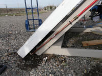
Update April
23, 2010
I redid the plumbing at the collector
outlet to eliminate any possibility of a a bubble trap. The new
arrangement is shown just below, and the old arrangement is shown in the
pictures above "Collector outlet and tank inlet".
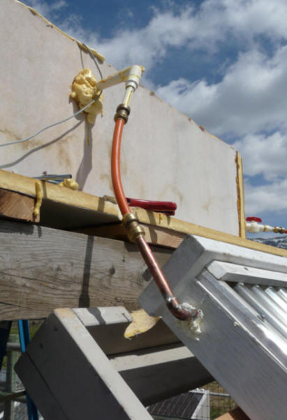
New plumbing at
collector outlet to eliminate the possibility
of a bubble trap.
The idea was to see if this stopped
the incidents of no flow that show up in the performance plot above for the
22nd. See the plot below for the results.
It appears to me that this did the
trick. I don't see any of the episodes where the collector temperature
rises and the tank inlet water temperature falls that can be seen on the plot
above, and indicate to me that no flow is occurring. On today's plot
there are a couple drops in tank inlet temperature, but they are not accompanied
by rises in collector temperature, and, for the most part, they seem to
correlate with drops in sun light intensity from clouds passing.
So, I'm about ready
to believe that you just have to be very very careful about the plumbing for
these thermosyphon collectors. No dips at all that could catch bubbles.
Note that on both
days, I flushed the collector completely of air before starting by basically
filling the tank through the collector with a garden hose to flush out any air.
So, it does not
matter how good a job of getting the air out you do before you start, the
collector makes its own bubbles -- presumably from water vapor.
Interesting also how you can see the temperature stratification band reaching
the mid tank temperature sensor at about 2:20pm and causing a rapid rise in
temperature at that depth as the band passes through that level.
The temperature rise
through the collector is still a pretty strong 55F.
But, all in all, I
think this configuration performs pretty well, and given its extreme simplicity
makes a pretty attractive solar water heater if your climate (no freezes) and
plumbing system are compatible with it.
I've received a few
suggestions that I will probably try to incorporate over the next week or so.
If you see any plans for a well proven thermosyphon water heating collector,
please point me toward them.
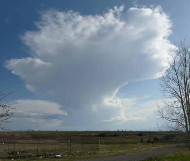
The Weather Gods signaling end of test.
Gary April 22, 2010