What follows is a very detailed
description of the conversion of a 1998 VW Jetta TDI to burn straight vegetable
oil. The oil could come from used fryer oil recycled from restaurants, or
vegetable oil from various crops.
Diesels designed to burn standard
diesel fuel need some modification to burn straight vegetable oil:
Thanks very much to Jeff for
providing this detailed description of the conversion. In the
Frybrid forum, he
posts as JeffNLisa, and is happy to answer questions or provide information.
OK – At long last (for me, that is!!) this thread has the
pictures and descriptions of the Frybrid installation for my
98 Jetta. I have widely stated that my brother did this work
AND that we plan to offer installation service. So I might as
well offer up the evidence . . .
I’ll cheat and start with a pic of the finished installation!!
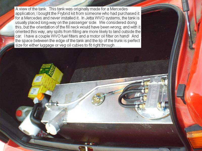
Let’s begin with tank location. This kit was originally
packaged and assembled for use in a Mercedes G-Wagon. The
buyer of it ordered it for his G-Wagon, then changed his mind
about the G-Wagon and sold it. He then put the complete and
unused Frybrid kit on eBay. So the tank it has was intended
for a different car.
The tanks for A3 Jettas are normally intended to run the long
way on the passenger side in the trunk. However, the tank I
have was intended to go side to side up against a back seat,
which in the Jetta would block the fold-down back seat. But if
we installed this tank long ways on the passenger side, either
direction would place this fill neck in a virtually
impossible-to-fill location.
So we located it snugged up against the back of the trunk:
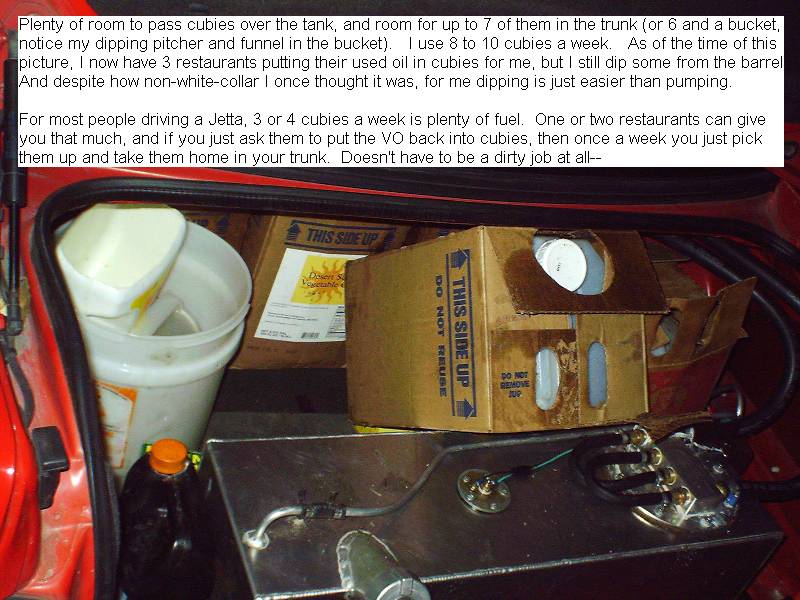
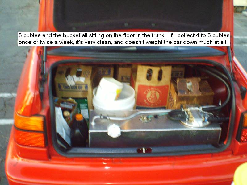
Anytime I am filling by pouring from cubies, I use a long
funnel that hangs out over the bumper, and that keeps drippies
out of the trunk.
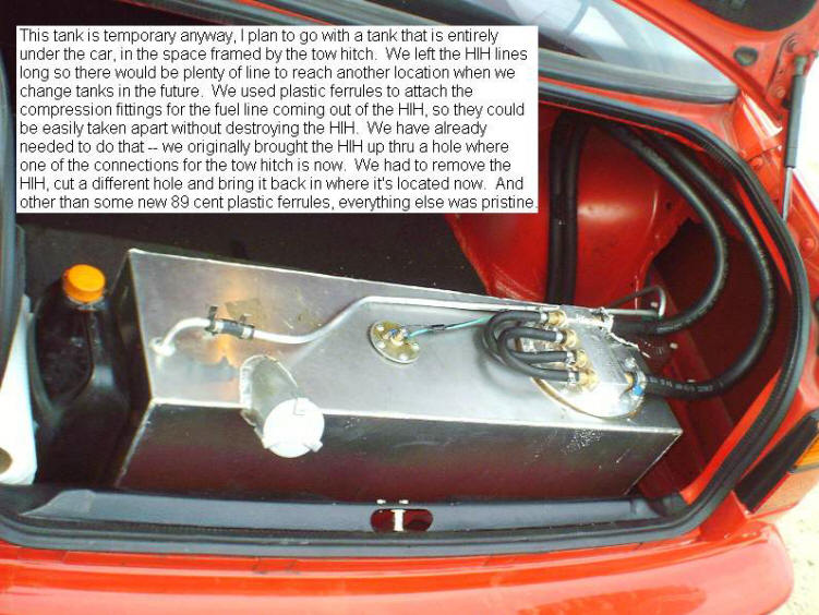
This tank is temporary. I always wanted an under-car tank,
so as to keep all the trunk space available. I am now shifting
my thinking to the idea of having several tanks in the trunk,
one in the left side as a vacuum collector, one in the right
side as a heated vacuum-boiling de-watering tank, and a main
tank that uses ALL of the space behind the seat. I never use
the fold-down rear seat anyway, and this arrangement would
still leave some space in the middle of the trunk.
I do want to perfect such a system in the garage first,
then in a truck where there is more room to maneuver, and only
then consider it in a Jetta. Maybe by then, Chris Goodwin will
have already perfected it, and I can save a few steps! But for
now this is workable. And it is adequate room to fit in
luggage, or as I have often done, cubies of WVO . . .
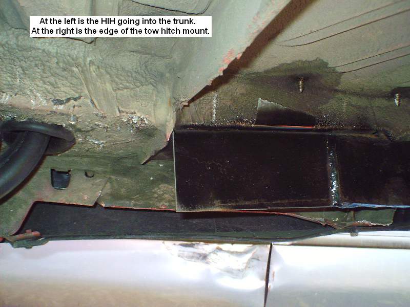
HIH Lines
We left the HIH lines long so they could be easily moved,
and we’d have length to get to other location(s) if needed. We
used plastic ferrules for attaching the HIH to the tank, so it
could be removed easily when that time comes. And when putting
in the tow hitch, that time came much sooner than
anticipated!! See THIS thread
http://www.frybrid.com/forum/showth...lastic+ferrules for
a discussion of the plastic ferrules, and see THIS thread
http://forums.tdiclub.com/showthrea...838#post1176838 for
a discussion of the tow hitch.
When we first finished hooking it up, I didn’t run a line from
the vent to go outside the car. Found out right away, that
some WVO finds its way out the vent routinely!! So we took a
canola oil bottle and made an overflow bottle out of it,
running the vent tube into it, and then venting that to the
outside through the floor of the trunk:
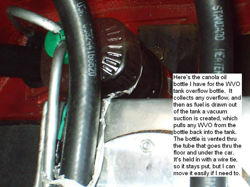
Any overflow is collected in the bottle, and then as fuel
is drawn out of the tank creating a slight vacuum, the suction
pulls any WVO in the bottle back into the tank. I used a wire
tie to hold the bottle secure, so I can move easily if needed.
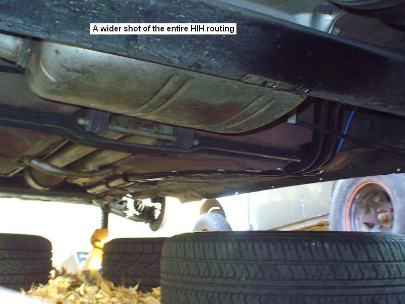
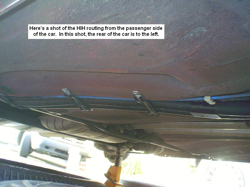
HIH Routing Under the Car
They turn toward the front,

Route snugly under the stock tank (notice a piece of fuel
line split down the length is used to protect the HIH from the
edge of metal),
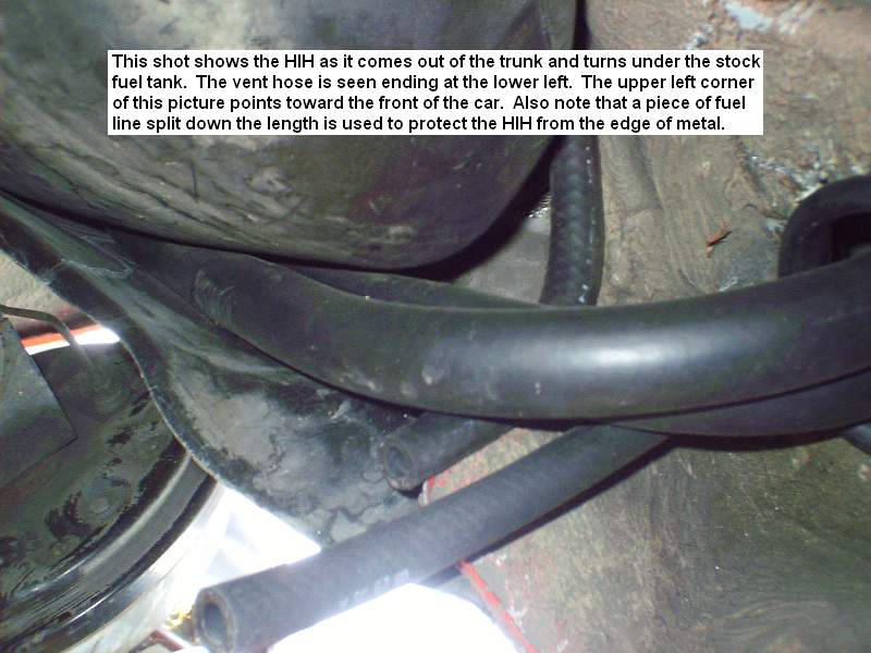
plenty of clearance over the axle,
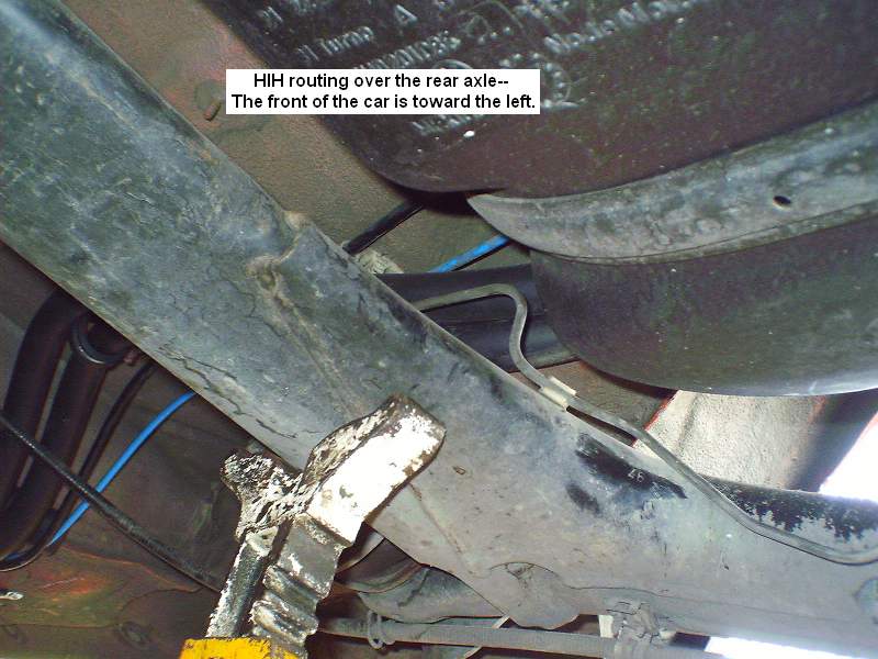
and follow the same channel as the stock diesel lines:
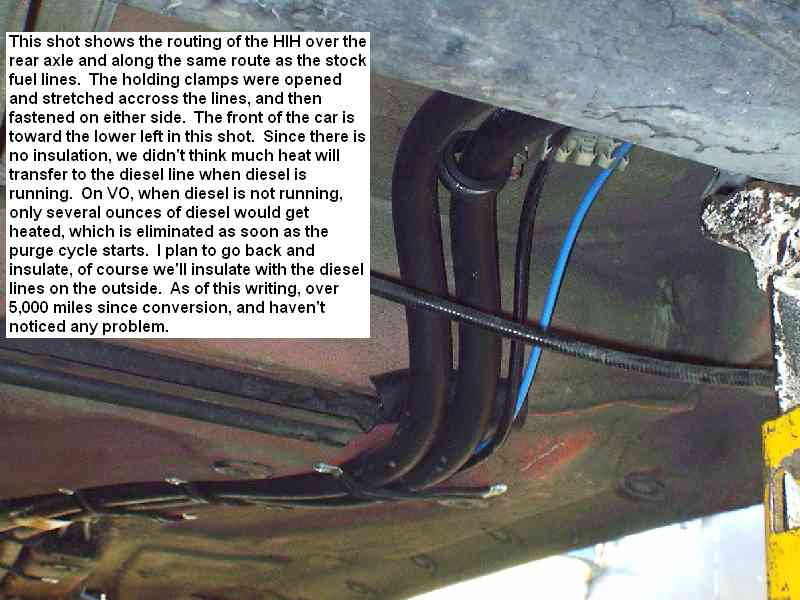
We opened the holding clamps and stretched them across the
lines and fastened them on either side.
Right at the firewall, they go into the engine compartment
also along similar routing to the diesel fuel lines:
We considered that the heat from the HIH might hurt the
diesel. But when running on diesel, the fuel is only in those
lines for a moment, because it is flowing. And with no
insulation or wrap to hold heat or transfer it to the diesel
lines (like a HOH) we reasoned that not much heat would get
transferred. When running on WVO, the diesel is stationary in
that line, but only a few ounces of it would get any heat, and
this is used immediately upon purge, replaced with cold
diesel. When I tagged the picture I had 5,000 miles, an as of
this posting I have over 9,000 miles on WVO, and have not
noticed any issues with this. We intend to go back and
insulate the HIH lines. When we do that, we will of course
leave the diesel lines outside that insulation.
In the Engine
Compartment
In the engine compartment the routing of the lines is hard
to see, and so the pics under the hood go in the order the
components are placed, rather than the order of flow.
To begin, under the hood we removed the stock air box. It
takes a ton of room, and is only somewhat efficient. The TDI
Club, I’m told, suggests against the use of K&N filters, but I
have used a lot of them, and they are the best.
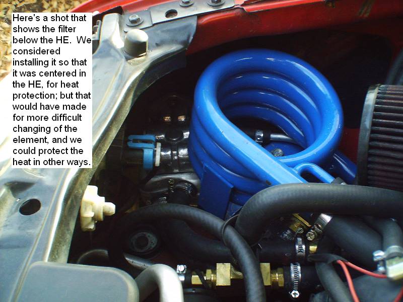
In the space left from removing the air box, we located the
heated WVO filter low in the front right corner, and the HE
about where the edge of the air box was:
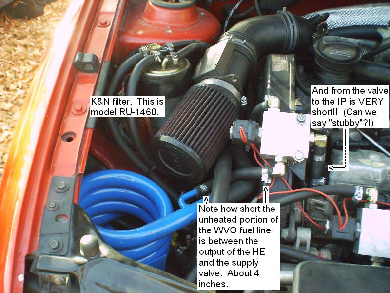
The K&N we used is model RU-1460. No dealer or supplier we
could find stocks this filter. There is even a K&N warehouse
in Riverside, and they do not stock it there either! This was
only a concern because for special order items, you have to
pay first, and it’s a one-way ticket. If it doesn’t fit the
space, you’re stuck with it. However, we measured, checked and
measured again, and according to K&N’s catalog, the
measurements we took exactly matched this unit. Most parts
stores can order it, and we got in about 2 days. It is a
perfect fit for the space.
There were two drawbacks to removing the stock air box and
using a K&N as we did in this application. One is that it
eliminates the cold-air intake. (Placing the filter in the
location of the cold-air intake led to another problem we had
to solve, discussed in a moment.) And second, the un-insulated
HE is here, and air coming to the K&N must pass by it if not
over it.
But I have noticed no degradation in performance, and the
greater surface area of intake with the K&N may also reduce or
eliminate any associated problems. I plan to insulate all the
Frybrid lines anyway, to keep heat in for WVO purposes. By the
summer, if performance degrades, we have contemplated an air
dam and tunnel that will more directly feed cold air to the
K&N.
In locating the valves, we were concerned with appearance, but
only to the degree that we could hide them under the cover.
Aside from that, functionality was the primary criteria in
locating them. We fabricated brackets to hold them in the
desired locations. For the supply valve, as close to the HE as
possible was important, so we would have a minimum of unheated
line after the HE and before the valve. Then we wanted that
whole assembly to be as close to the IP as possible. We got
about 4 inches and less than 2 inches for the final result!!
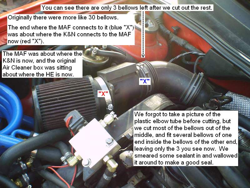
Next came the problem of mounting the K&N. The stock air
intake feeds through a plastic elbow, around the back of the
valve cover to the turbo. Fortunately it is bellowed for about
10 inches, and we were able to cut it at one end about 3
bellows from the MAF, and cut off all but about 3 bellows on
the other end, just before the bend. We then fit several
bellows from the one end into the other, smeared some sealant
in and wallowed it around to make a good seal, and achieved a
perfect shortened intake!
For maximum efficiency and speed of the purge cycle, it is
important to have the shortest possible return line from the
IP to the return valve. We achieved just over 3 inches here:
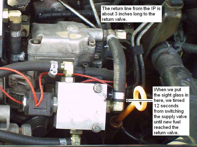
When setting up the purge cycle we put the sight glass in
the joint at the end of this line, and then from the sight
glass into the valve. We timed the cycle for fuel-change to be
12 seconds for the fuel to “completely” wash thru to the
replacement fuel at this point. I have contemplated putting a
delay relay into the switchover process, so as to give the
return valve about an 8-10 second delay when switching over to
WVO, just to save the few ounces of diesel that normally feed
to the WVO tank at switchover.
The next most important thing in setting a good purge is to
minimize unheated line after the valve and before the entrance
to heated line. We could have located the terminus of the HIH
for the return line right next to the valve, but it was much
cleaner to locate it where we did:
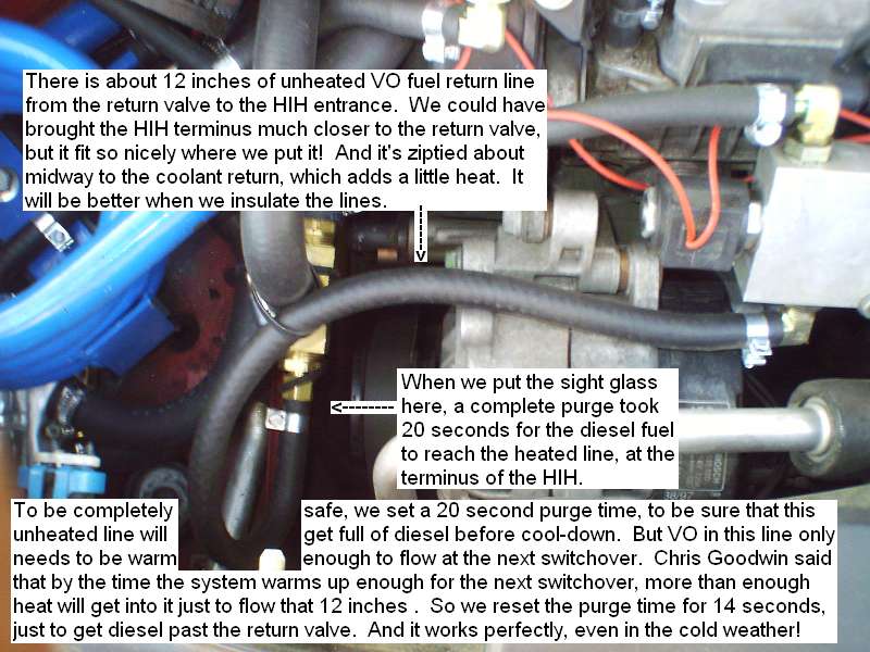
But to be sure we didn’t leave any VO in unheated line; we
originally timed the purge cycle to run diesel all the way to
the entrance of the HIH. An additional 12 inches. By placing
the sight glass there in the line, we timed that to be a total
of 20 seconds. So an additional 8 seconds purge time to have
the HIH terminus where we wanted it, for that additional 12
inches of unheated fuel return line.
However, Chris Goodwin later told me that it was safe to
purge only to pass diesel thru the switch valve, and leave WVO
in that short of a line. He said that by the time the car has
warmed up enough for switchover next time, sufficient heat
would travel thru the ounce or two of WVO in just 12 inches of
line to make it flow, and flow is the only concern. So we
reset the purge cycle to 12-14 seconds, and it has worked
perfectly.
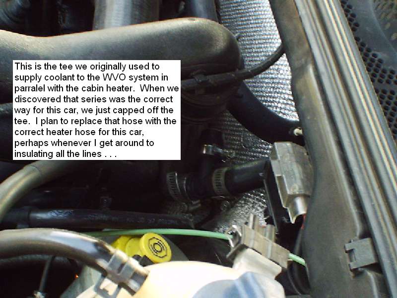
To get the heat to the HE, at first we teed into the heater
hoses that feed the cabin heater. When buying a kit off of
eBay, I got one with parts and instructions for a different
car, that IS supposed to be plumbed that way!! But we found
when running it that virtually no heat goes thru. When I
posted a question to ask, Chris Goodwin said that either an
aux water pump or re-plumbing in series was the correct way to
do a TDI VW. We had already tried it the other way and found
that out for ourselves by the time I saw his answer on this
forum . . .
So on my car, the coolant travels into the firewall to the
heater core thru the hose on the driver’s side, and then out
the firewall back to the engine thru the hose on the passenger
side. (Apologies to Aussie Bloke, Tony from West Oz, WVO
Downunder, et al. for the wrong orientation for them!) We
spliced into that return line, and fed that coolant to the WVO
system. In TDI VWs (mine at least) coolant flows thru the
heater core at all times, and heat is diverted into the cabin
or not, simply by controlling whether the fan blows air thru
it or not.

Later we also found that we could still decide on-the-fly
whether to take heat in the cabin first or send heat to the
WVO system first. If you select heater on in the cabin, the
air will transfer all the heat it can from the coolant to the
air flow, just as if the WVO system wasn’t there. If you
select heater off, virtually all the heat travels right thru
the heater core and on to the WVO system. This is remarkably
efficient. I really can select it on the fly and take all the
heat, or give it all to the WVO system, or any combination I
feel like depending on how cold it is!!
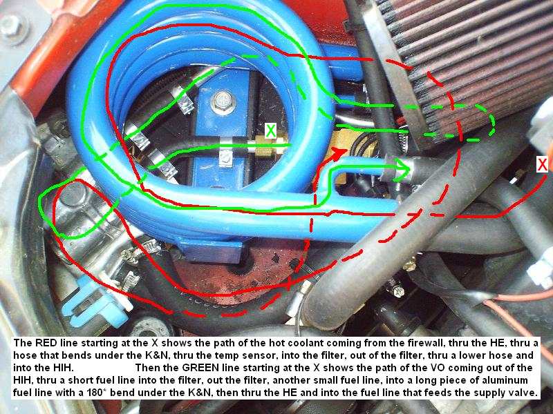
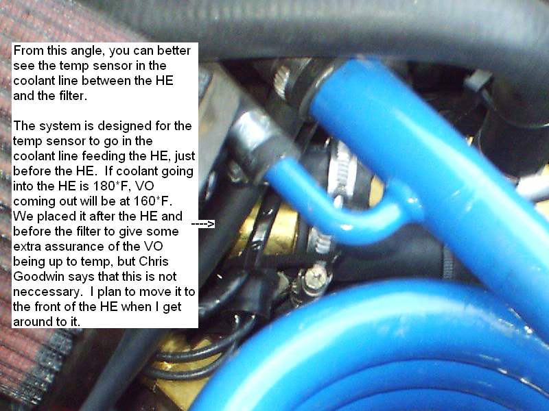
The coolant travels over to the HE and enters there. The temp
sensor is supposed to go in the line right before the HE, but
we wanted to be safer at the beginning, so we located it after
the HE and before the filter. So coolant flow is HE, temp
sensor, then it goes into the filter. From there it goes into
the HIH back to the tank, through the in-tank HE, then thru
the other HIH back to the terminus where the fuel return line
is. It then is routed back to the engine head.
The WVO comes from the tank, thru the HIH, thru the filter,
thru the HE, the supply valve, the IP, the return valve, the
other HIH, and back to the tank. The lines are routed tightly
and closely, but fit in very efficiently.
Under the front of the right fender is the access to drain
or change the filter element:
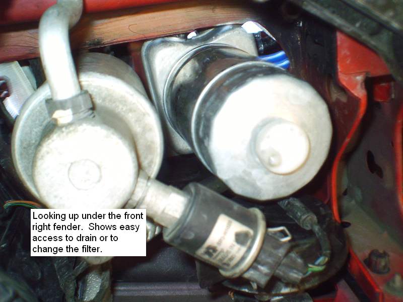
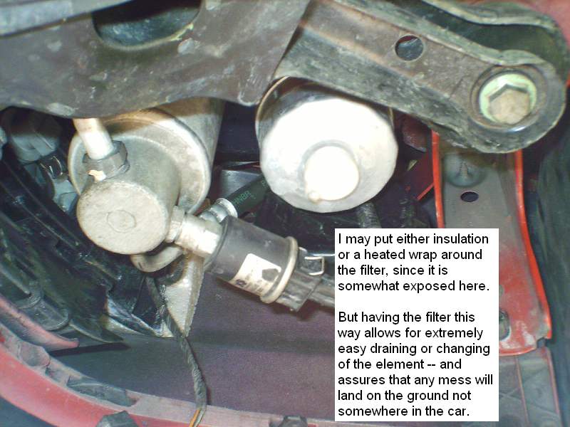
This is real nice, because the drips that leak when
changing it all land on the ground, not in the car. Also, when
changing the filter, I simply fill the new one to the top with
diesel or fresh filtered WVO, and at the next switchover,
there is never any hiccup from any air in the fuel line.
I was concerned about having the filter this exposed. I have
contemplated putting either insulation around it, or even an
electric or coolant heated wrap. However, as it was
engineered, it stays blistering hot, even with cold wind that
might hit it. I have had a few problems which may be related
to cold in this filter, but have not been able to conclusively
determine that to be the cause. Still, when I go to insulate
all the lines, this will probably get an insulated cover for
it.
As I said already, it sits in the space where the cold-air
intake was. To protect it from direct air blowing across it we
welded in an air dam to block the original path of the
cold-air intake.
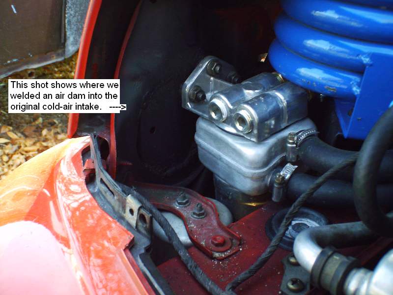
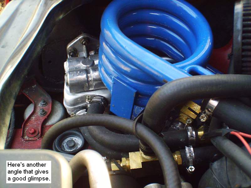
It is also visible in this shot, which shows a better view
of some of the lower hose routing.
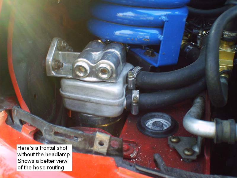
And from this angle you can get a good perspective of the
filter location.
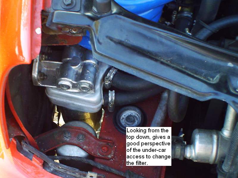
And another perspective:
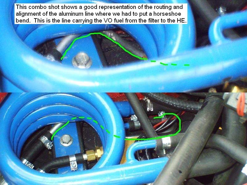
This orientation of the filter and HE led to a problem of
how to flow the fuel from the filter to the HE. The path it
must take exits the fuel outlet of the filter, travels several
inches, then must make a 180* turn and into the HE fuel inlet.
Heater hoses are made that have 180* bends in them, but we
could not find any fuel line that does. But heater hose would
not hold up to fuel. We considered that it MIGHT hold up to
WVO, but there would certainly sometimes be diesel or
BioDiesel in the line. I asked on the Frybrid forum, and
several including Chris Gooodwin responded that even WVO would
break down heater hose over time. Chris suggested bending a
piece of aluminum line and using that. And that’s exactly what
we did!
Here you get the best view I can show of how that line goes:
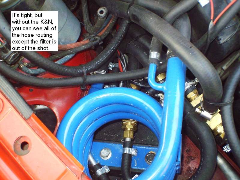
With the K&N removed, you can see the routing of the diesel
lines:

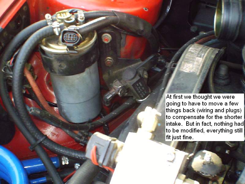
There were several electrical and structural arrangements
that were designed for the location of the MAF. When we
relocated it, at first we thought that several of those
electrical and at least one mechanical assembly would have to
be relocated. But in the end, they reached from the existing
locations, and nothing had to be moved:
Here’s a final view of the routing of the lines and flow of
coolant and fuel. The first shot is straight with no
diagram, then the same shot with a diagram of flow drawn on
it:
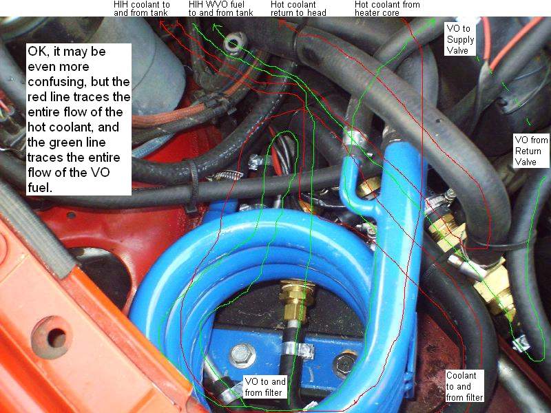
All in all, I think it’s a clean looking installation!
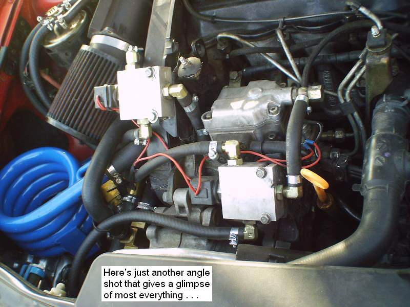
The location of the valves and components was designed not
only for efficiency of operation, but also for cleanliness of
appearance, and to appear either hidden or as close as
possible to stock with the cover fitting back on:
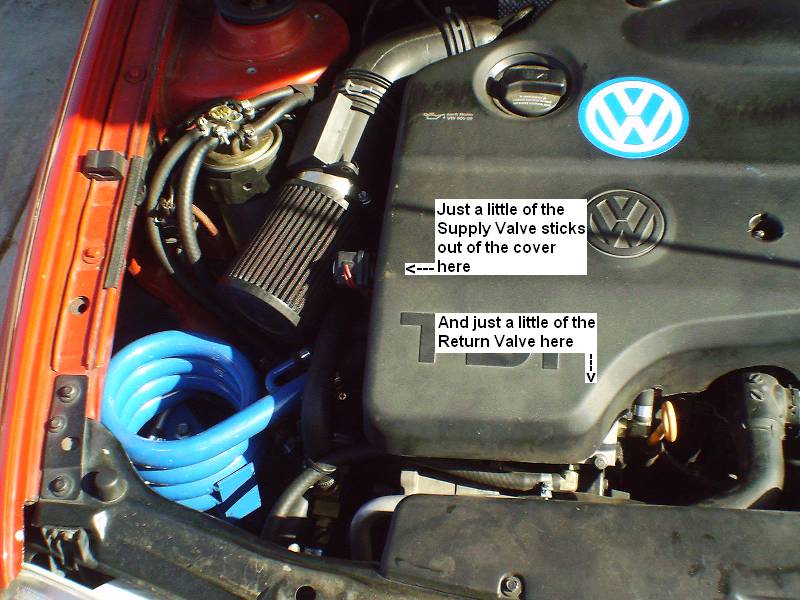
And again, this is the “final product” view under the
hood!!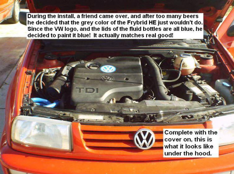
In and through all this, I am not suggesting that these are
the “best” locations or the only logical locations for these
components to be located. I am simply showing where we decided
to locate them, and why; and what we did to solve any
associated problems.
In the Cabin – The Frybrid
Controls
And then into the cabin for the Frybrid controls.
I did not want any extra gauges in the cabin. I wanted
everything to remain as stock looking as possible. So to begin
with, we did not mount the provided VDO fuel guage. Instead we
wired it in to the stock fuel guage, which I will show in a
moment.
We considered a custom panel for the LED lights and button and
switch. But we found an unused blank in the dash board that we
could very tightly fit the lights and button, and although
this was a difficult fit on the back, it looks very clean on
the front: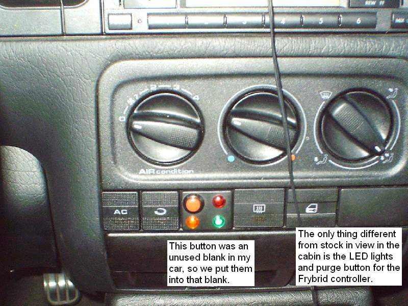
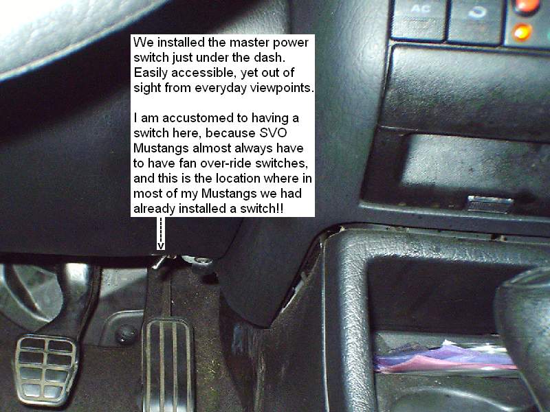
I did not want the switch in view in the cabin. In my
“previous life” with Mustangs, it is common for the cooling
fans not work well in fox-body Mustangs, particularly the
turbo charged ones. And so in nearly all of my Mustangs we had
wired a fan over-ride switch, and located it just under the
dash to the far right side. I was very familiar with how easy
this location is to reach, while at the same time being hidden
from sight. This is where we located the master power switch
for the Frybrid system:
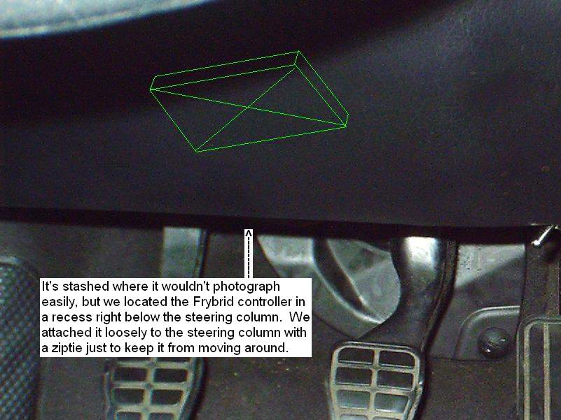
And the Frybrid controller is located just up under the
dash, hanging right under the steering column. That area does
not lend itself well to photographs at all, so here’s a
“ghost” drawing of its location:
Use of the stock in-dash fuel gauge for both fuels
In a PREVIOUS “previous life” I used to have a fleet of Ford
Econoline vans. The ones that had 2 tanks had a switch up
under the dash on the left side of the column, that you
would switch tanks, and the fuel gauge would change to
register the level of whichever tank you were currently
using. Since I got quite used to that, this is how I wanted
it in my Jetta, even way before I thought about how to
accomplish it.
Then I saw where Brian (ourwebstop) had posted pics of his
conversion and setup. Go to
http://vw.ourwebstop.com/ and click the link to
pictures. In his pictures is a pic and link for
directions for the fuel guage modification that he did. If
you follow the link in Brian’s pictures, you can read it.
The sender unit that came with my Frybrid tank didn’t work
exactly right that way, and we started with several
resistors and tested the resistance of the circuits. In the
photos to follow I describe how we accomplished it instead.
Even though it worked out differently for my car and my
Frybrid tank sender unit, I wish to extend SPECIAL thanks to
Jamie Braman (whom I’ve never spoken to) for letting Brian
post his how-to document. And SPECIAL thanks to Brian for
posting it!!
For the fuel gauge, the first thing we did was open the
hatch door to access the sender unit, which in the 98 Jetta
is in the trunk under the carpet to the right of the spare
tire well.
(Picture of Fuel Sender hatch in trunk -- to be
added later here)
We then spliced the live wire that comes from the stock
sender and attached it to the default closed position on a
SPDT relay. We brought the live wire from the Frybrid tank
sender, and attached it to the normally open position on that
relay.
(Picture f wires coming from stock sender, and splice
of sender wire from WVO tank -- to be added later)
We wired the trigger power to the relay to come from the power
to the supply valve. That way, whenever the supply valve is
not powered (fueling the car with diesel) the relay trigger is
not powered, and defaults to its #1 position, which closes the
link between the gauge and the stock tank sender unit.
Whenever the supply valve is powered (fueling the car with WVO)
the relay trigger is powered, and switches to the #2 position,
closing the link between the gauge and the WVO tank sender
unit.
(Picture/schematic of relay. This is a SPDT
relay, with default to postion 1 -- to be added later)
We got some resistors and an electric multi-meter. After we
tried several resistances, we determined that even NO
resistance still would not allow the gauge to read all the way
to “full” with the float ball all the way up in the tank. This
was easy enough to check with the sender still in the tank; we
could use a piece of wire to reach into the tank and gently
lift the float ball to the ceiling. That only took the gauge
up to about 2/3 full reading. But I drove it this way for
several tanks, just to make sure that it was moving up and
down, and that it was switching to read the 2 tanks.
So we had to remove the sender unit from the tank, and adjust
it. We determined that with the wire of the float ball all the
way up to the max position on the sender, that the gauge would
indeed read full. But then the ball would be WAY higher than
the top of the tank! We found the spot where the “fuel”
warning light would come on, and that would have the ball
floating at over half full in the tank.
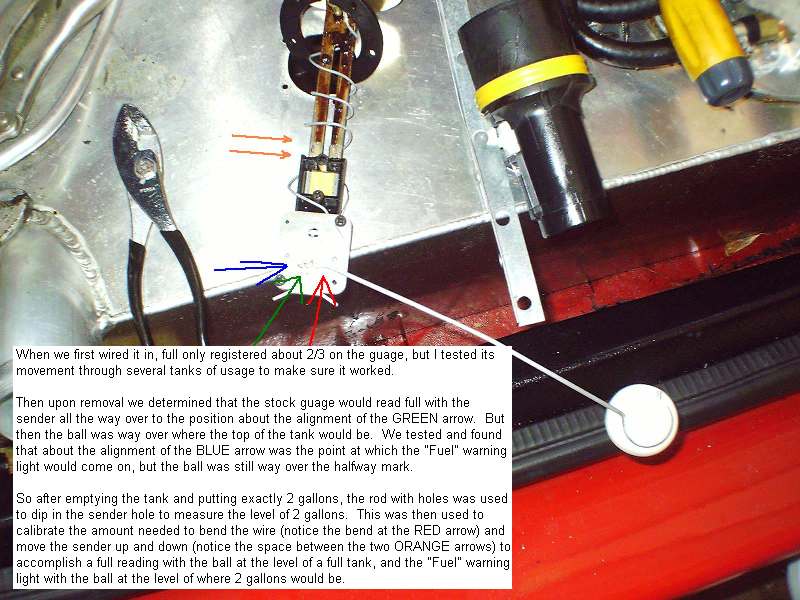
We emptied the tank and put in exactly 2 gallons. We used a
stick to dip into the sender hole, to mark the level of fuel
for 2 gallons, and then set that alongside the sender unit. By
trial and arror, we adjusted the height of the sender up and
down on its rail, and a bend in the wire that holds the ball;
and located it so that when the ball was where a full tank
would be the wire had the sender all the way up, and when the
ball was at the level of 2 gallons, the wire had the sender at
the point where the “fuel” light came on.
This alignment works perfectly, and gives 10-11 gallons of
usage before the “fuel” light comes on, and gives a reserve of
2 gallons of WVO when the light does come on.
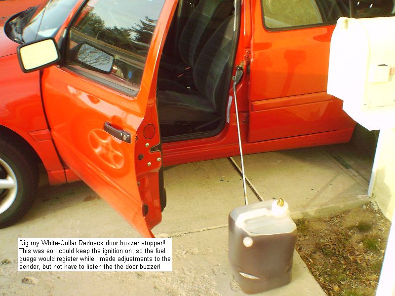
For testing, it was necessary to turn on the ignition to the
run position, but not start the car, and short pins 3 and 4,
so the green light would come on, and adjustments to the tank
sender would register immediately on the gauge. (When the car
is moving, changes do not register instantaneously, as
described below. But when the car is still, they do.) When the
ignition was on, the “door open” buzzer was irritating, so I
facilitated a temporary disabling device, with the help of a
golf club and a cubie of WVO . . . .
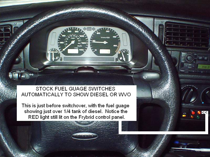
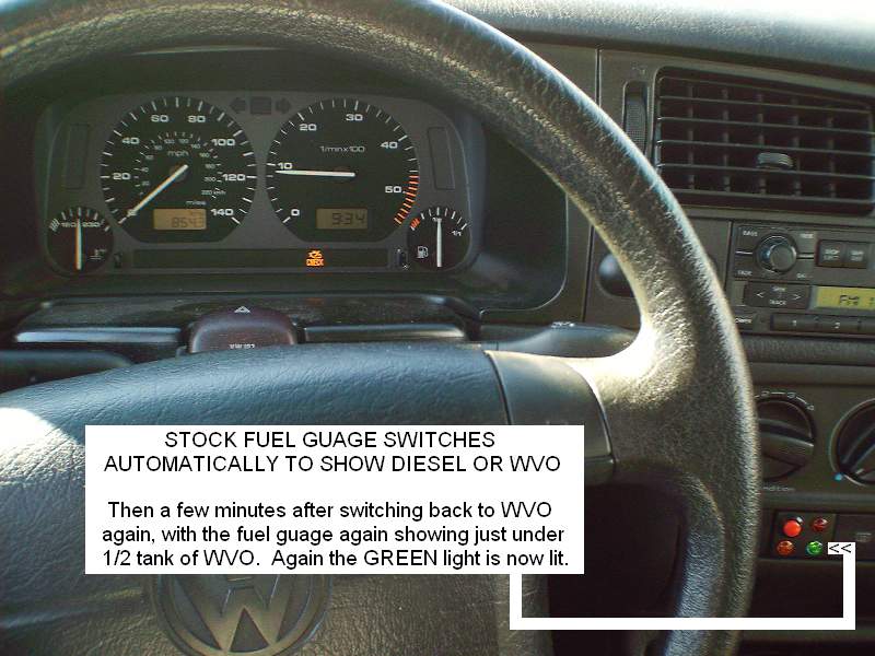
In the cabin, the fuel gauge works perfectly with the
exception of a significant delay in changing readings when
switching. In this photo, the car has almost warmed to
switchover temp, but you can tell by the temp gauge that it is
not quite there. And you can see the RED light on the Frybrid
controller to indicate diesel. The gauge shows the level of
diesel I have in the stock tank:
I resumed driving and once it warmed enough and switched
over, the gauge then moved to show the amount of WVO in the
Frybrid tank:
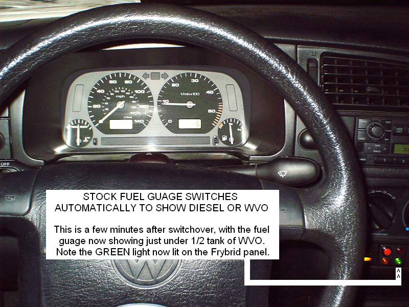
You can't read the clock on the dash board very well, but
the elapsed time is about 10 minutes.
The only problem with this operation when driving is that the
gauge doesn’t move to the new level instantaneously, unless
you are sitting still. The ECU takes readings from the sender
every few seconds. When the car is still, it displays those
readings directly to the gauge. This way, when you stop to
fill up your empty tank, when you turn on the car, it senses
the new level and displays the new level immediately. But when
the car is moving, the float ball bounces around in the tank.
Even with momentary readings, this would cause some erratic
behavior on the gauge! So while moving, the ECU takes these
readings from the sender every few seconds, and holds them for
a period of time, and averages them for the reading it sends
to the gauge. This smoothes out and eliminates the erratic
behavior of the needle when driving, and the level of the tank
drops relatively slowly, so that in the stock design each
reading gets slightly lower as the fuel is used, and the
overall average does go down so the needle on the gauge does
go down as the fuel is used.
This functionality though serves to foil the switchover. When
driving, if the ECU has been detecting readings near half
let’s say, and then at switchover the readings are now at
full, let’s say, it will add a full reading into the average,
which raises the average a little, but not a lot. As more full
readings get included into the average, the average gets to be
larger and larger, and the needle gradually moves to the new
level.
In practice, this takes about 10 minutes. I have gotten quite
used to it, but does take about 10 minutes for the needle to
reach the correct level after switchover when driving. After
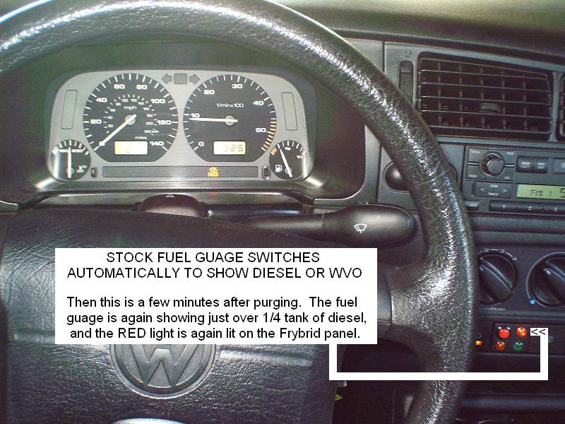
the switchover photo, I purged and the needle went back to the
diesel level:
Then I switched off the Frybrid controller and switched it
on again so it would switchover to WVO again, and the needle
went back to the level of the WVO tank:
Notice that each of these has about 10 minutes elapsed time.
I was already very accustomed to this 10 minutes of the
needle “crawling” when one day I had driven several miles of
a warmup, but I was sitting still at an idle when the system
switched over. This happened to me while sitting at a stop
light.
If the car has been sitting still for a minute or so, then
switchover will make the gauge needle move instantaneously
to the new position. I have tried to time it, and do not yet
have conclusive results, but the car must have been sitting
still for somewhere between 30 and 60 seconds for it to stop
“averaging” the readings, and start displaying the exact
reading instantaneously. I have also tested it on the purge
cycle, where if I stop and sit still for 30-60 seconds
before purging, the gauge needle will move instantaneously
back to the diesel level.
Brian (ourwebstop) and I were discussing this on the GC
forum, and TDIguy posted that the speedometer is of course
the device that the ECU uses to control this. So if there
were a way to trick the ECU into thinking that the car is
not moving for 30-60 seconds before switchover, it would
then register the correct reading on the fuel gauge
instantaneously. TDIguy mentioned that one of the fuses in
the fuse box controls the speedometer, and that if you pull
it momentarily (or rig a switch) then the speedometer will
shut off, giving the exact desired effect to the fuel gauge.
However, if driving at that moment, the gauge apparently
will start jumping around erratically a little. I also
really do not want to turn off the speedo for 60 seconds,
but I may experiment with it and post results.
I wish there were a way to trick the ECU to think the car
was not moving, but still display the speedometer reading in
the dash. However, I assume the ECU controls the
speedometer. If anyone knows a way to keep the speedometer
reading correctly on the dash, but trick the ECU into
thinking it’s at zero (for 30-60 seconds) I’d really like to
know about it!!!
__________________
WVO Fuel kit
INSTALLATION SERVICE
As of February 6, 2006 my brother is now officially offering
installation service for WVO kits.
We do NOT profess to be professionals at WVO, I do not think
we have nearly enough experience for that.
However, my brother is and has been a mobile mechanic for
most of his working life (he's 40). As of this writing he
does not want to begin doing installs at the customer's
location yet, until he has several more under his belt. This
is because there are too many things he might need to stop
and go get, such that he is not yet confident he can offer
it in a timely manner at the customer's location.
However, his location is Mentone, CA. This is near San
Bernardino, CA. Anyone wanting to have a conversion kit
installed can bring the vehicle, and I would be happy to
provide WVO-fueled "shuttle drop-off service" back to their
place as long as the distance is not extreme, and then
pickup service to come get their vehicle when it is
complete.
Basic kit installation is priced at $895, which will include
light custom bracketry that may be required.
Please e-mail me off-forum for specific questions regarding
hiring for an install.
Any questions about this install in my Jetta, please go to
http://www.frybrid.com/forum/showthread.php?t=3154
thread in the Frybrid forum and post there, and I will
answer!!


Jeff Stephan
You can email Jeff at:
dandsins@yahoo.com
One further comment from Jeff:
It should be noted that the Frybrid kit comes with
rubber fuel lines designed for fuel that will withstand
hot WVO. However, those lines are NOT designed to
withstand BioDiesel, and it is important to know that if
you install ANY WVO conversion kit, if you also plan to
use BioD you need to install viton fuel lines instead of
the ones I used, which are supplied normally by Frybrid.
When they have stock, I believe Frybrid is willing to
supply you with BioD-safe lines as an option, if you
request and pay the difference.
