Search
The Renewable Energy site for Do-It-Yourselfers
Cristian's Earth
Sheltered Passive Solar Home in Romania
| Cristian is an engineer in Romania, and has designed, built, and
lived in this passive solar, earth sheltered house for two years.
The house is very carefully laid out to make maximum use of space and
and the solar heating and lighting opportunities.
The house also has solar water heating, rain water harvesting, earth
tube heat recovery, and provisions for a PV array. The
house is heated entirely by sun and wood, and the total firewood bill
for a full winter is only $70!
Cristian says it took about 50 versions to get to this final design,
and I can believe it -- it shows a lot of careful design work.
Thanks very much to Cristian for sending in this detailed description
of the house! |
|
NEW:
Cristian adds a greenhouse...
And now the story...
After 20 years of stressful work as technical manager for a private company from
Bucharest ( Capital of Romania) I decided to find a nice and quiet place and
build a home with no future expenses. My children (two boys and a girl) have
finished their school, have jobs and need their own home to have a family. My
wife and I have always dreamed of having a home in a village with our own garden with
trees, flowers and vegetables and our own chickens, ducks, and geese for natural meat
and eggs.
In 2007 we found a place with 10,000 square meters at an incredible price
(0.5 $ per square meter), and with the perfect orientation (N-S) and with all
the facilities (water,
electricity, natural gas and good road). The property is located at the border of
the beautiful village of
Filipestii
de Padure.
We bought a trailer and in the autumn of 2008, we built the foundation.
The next
year, in May, we permanently moved there to finish the home. After six moths we
had moved in our new home, but still, there were still things to finish and mistakes to
correct.
How the House Works
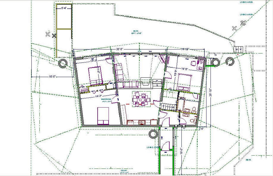
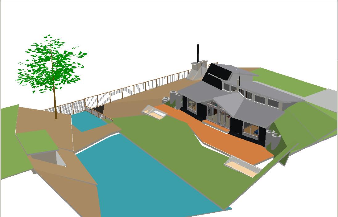
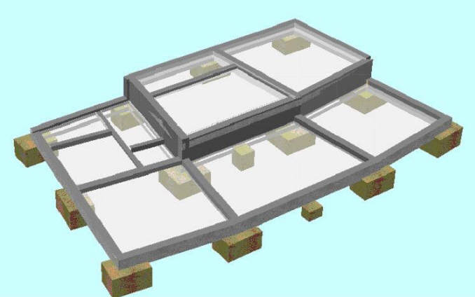
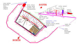
Plan view of the house as built.
The picture above shows the floor
plan for the house. This is the final version after 6 months of
studying American web sites about earth sheltered homes. We probably went
through 50 versions to get to this final one.
The South half of the house (with the
large windows) is
0.8m (2.6 ft) lower than the North half. This was a terrain
opportunity for having South
windows for North rooms as you can see in the pictures.
In these pictures you will notice, on the left and right sides of the South
wall, some big concrete tubes (1 m diameter) that are used to stabilize the
earth and also to store rain water. There is also one tube on the North side near the main entrance.
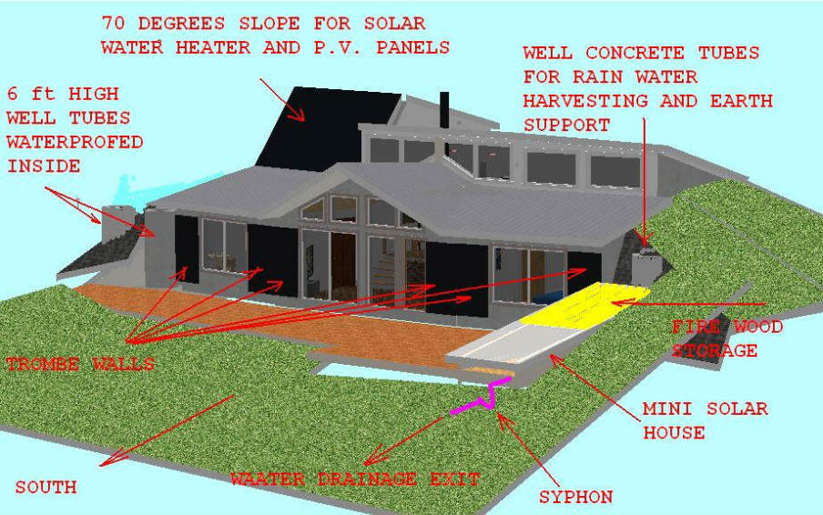
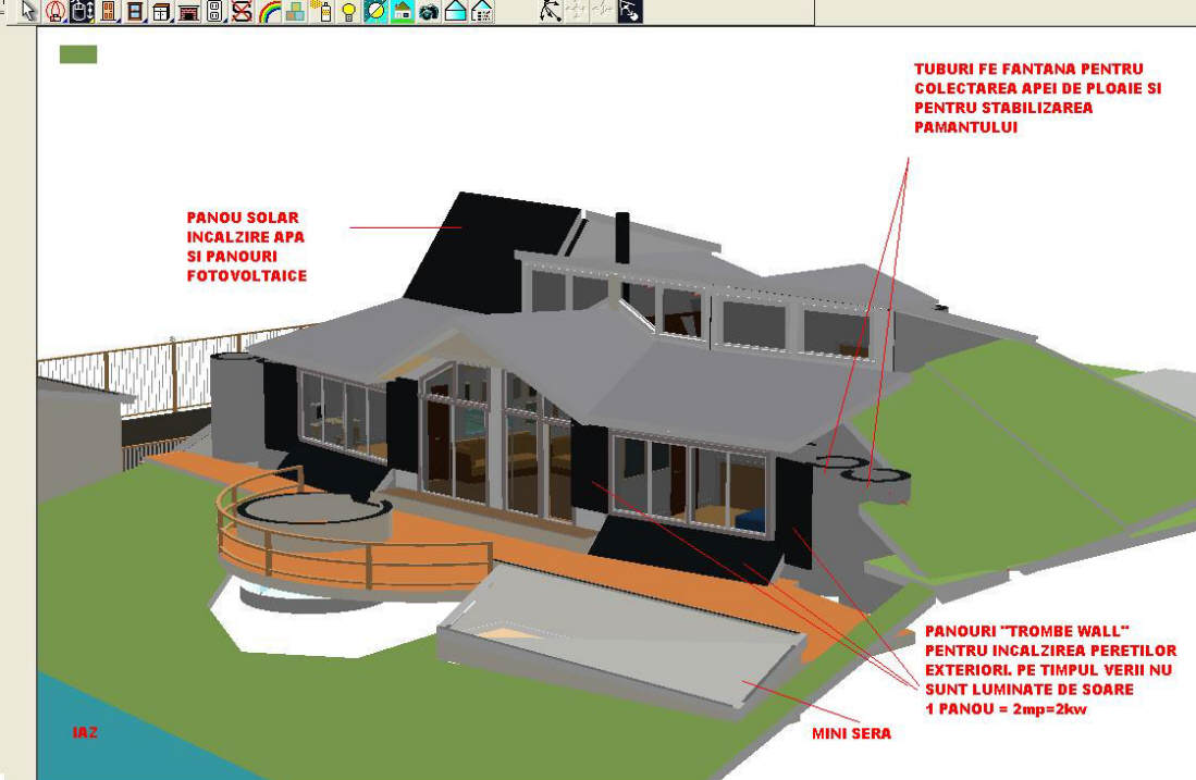
View of the house from the south showing the main solar features.
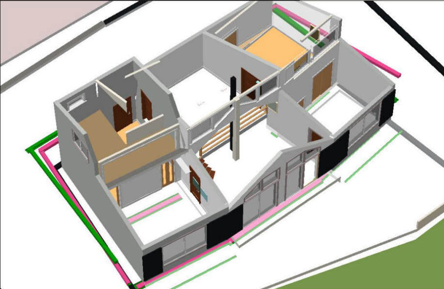
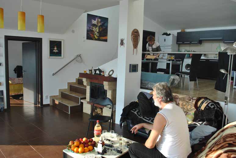
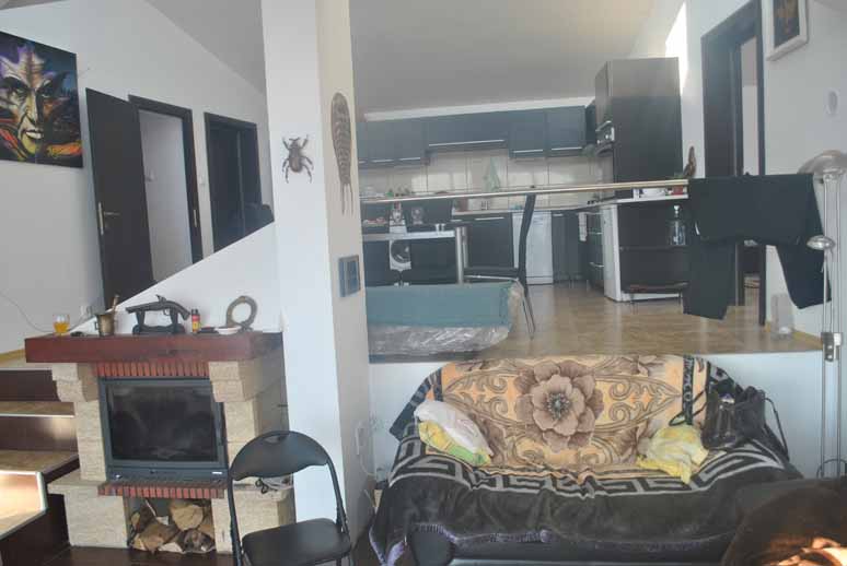
View showing the interior arrangement.
More views of the house from various
angles -- click on the pictures for full size.
|
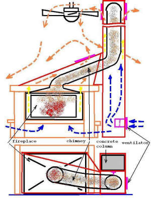
There is only one heating source, a fireplace,
located exactly in
the middle of the house.
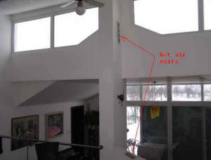
The picture to the right
shows the airflows for the fireplace heater, and the picture just below
shows the hot air vents for the fireplace.
|
 |
 |
In the NW corner, there is another room located above the main entrance, two bathrooms
and dressing. This room is above ground and I use it for painting and other
handcraft work.
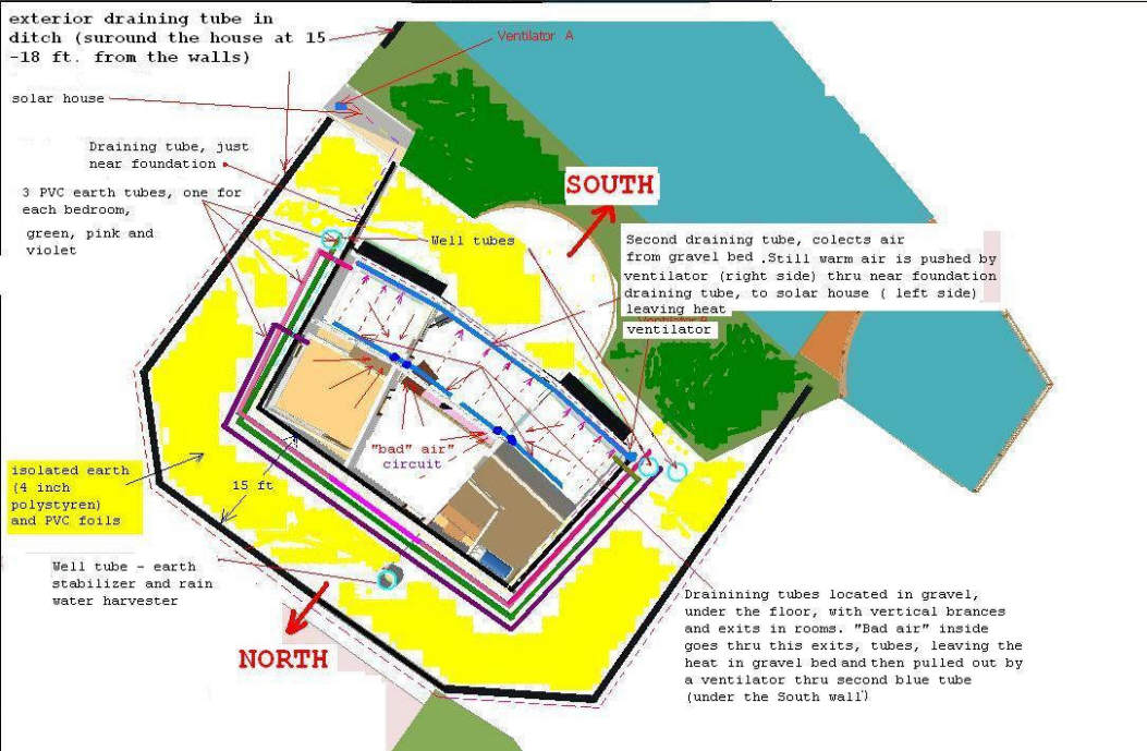
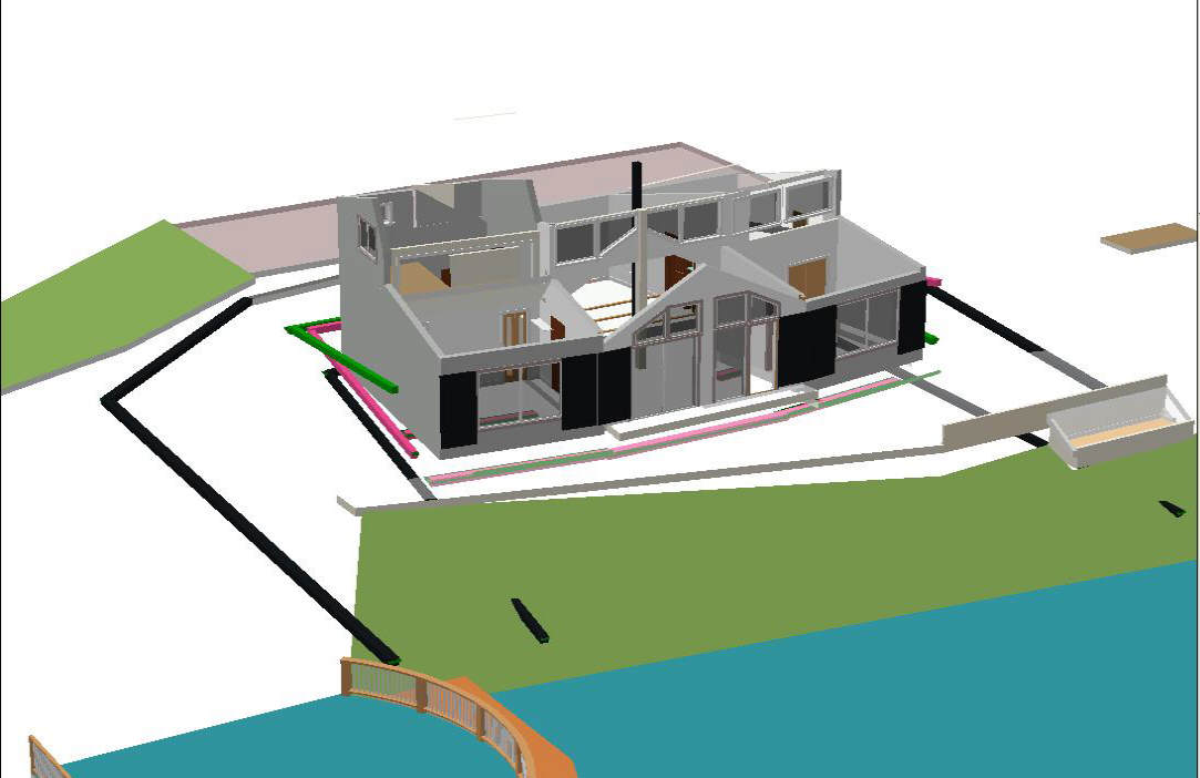
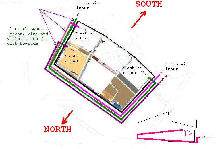
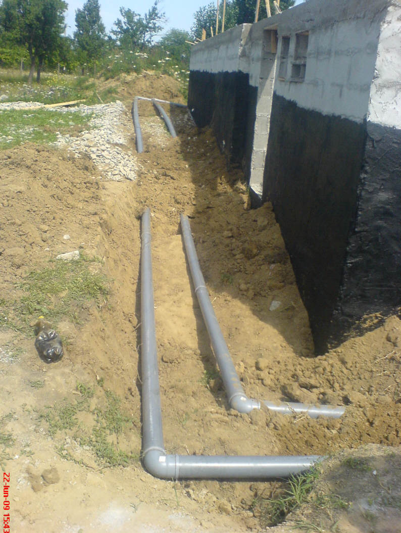
This picture shows the water drainage
and earth tube ventilation system.
From the picture, you can see the
tubes used to drain water away from the foundation (the black lines). One is near
the foundation and the other one is 5 meters (16 ft) away from the foundation walls buried at 0.5 m
(20 inches),
where the extra added soil is ending (to collect and drain rain water).
The pink, violet and green lines show the earth tubes used for energy
efficient ventilation. Inside of each tube is a small fan (15W), but I don't have
to use them because the natural air flow is sufficient.
|
This picture further details
the flow of the exhaust air leaving the house.
-
From inside the
house the stale, warm air goes down under the floor into the
gravel bed.
-
From the gravel bed,
the air is pulled out by a blower (right side) into a solar
panel which has not been built yet.
-
The air is
reheated by the solar panel and then pushed thru the drainage
tube near foundation, around the house to the small solar house
on left side of the house.
-
The air is reheated
again in the solar house and is pushed by a second blower to the
second drainage tube (5m from the walls) around the house,
again, and is finally exhausted out to open air.
The idea is to recover as
much heat as possible from the air before letting it go. |
 |
This picture details the flow of fresh air into the house.The earth
tubes preheat the outside air before it enters the house. |
 |
This summer I will modify the plan so that
the used air will enter in a
Trombe
wall, heated (in autumn and winter) then pushed to drainage tube outside
foundation ( black line) surround the home and enter in a small green house (on
the left side) heated again ( in summer) and pushed again in the exterior
drainage (5m from the walls) surround the house and the exits.
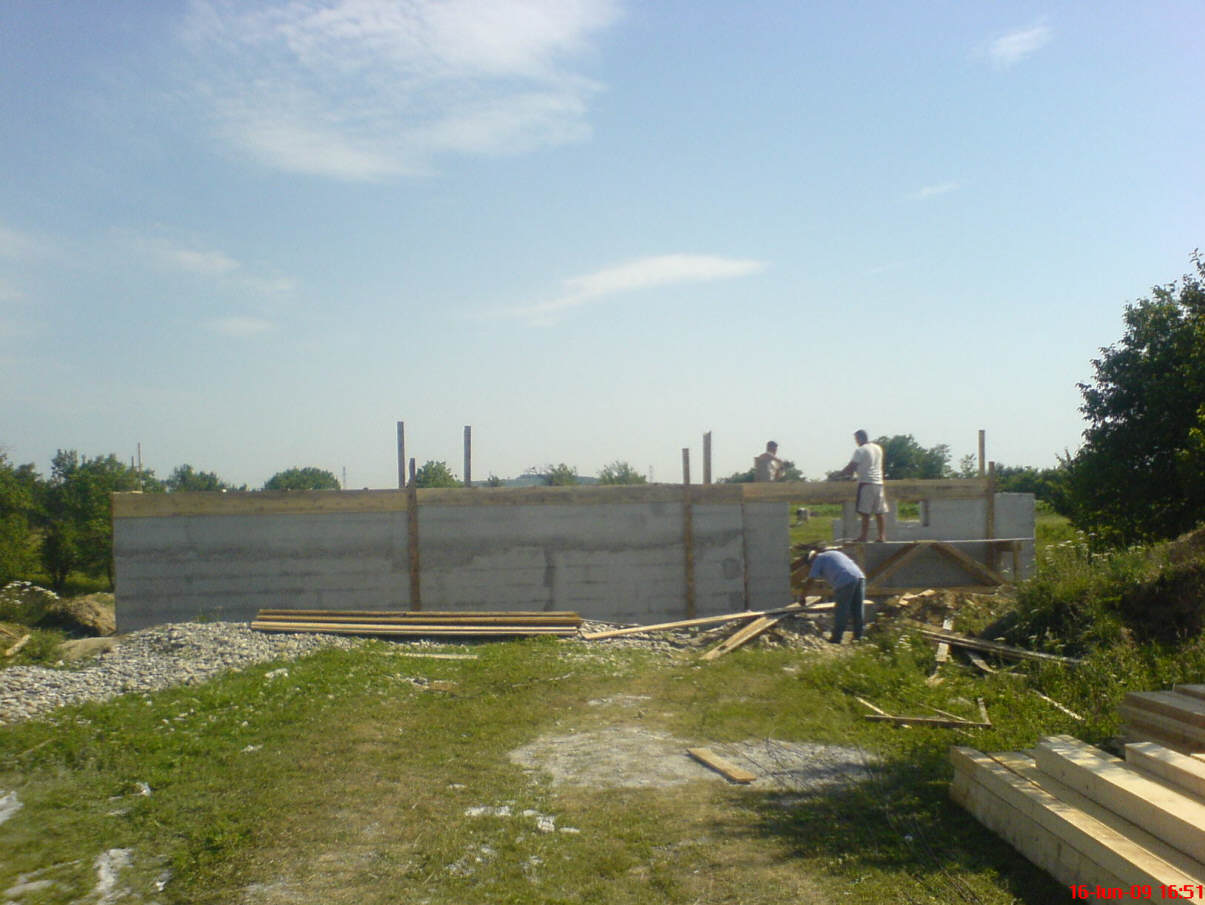
Construction Pictures
Foundation
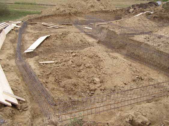
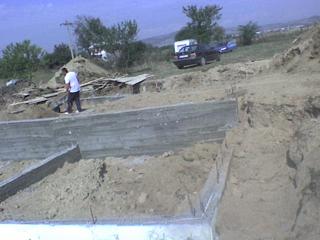
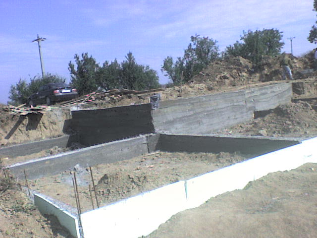
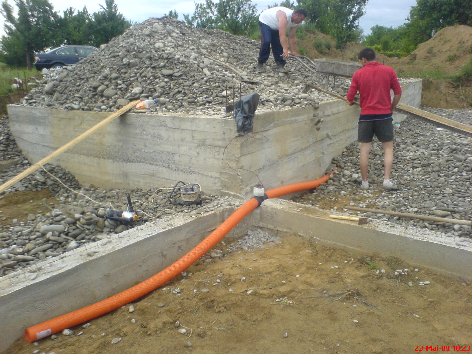
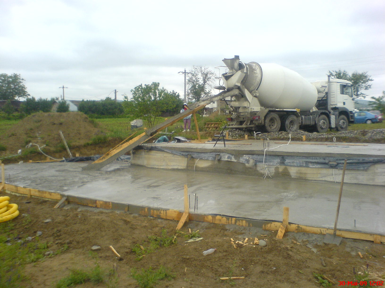
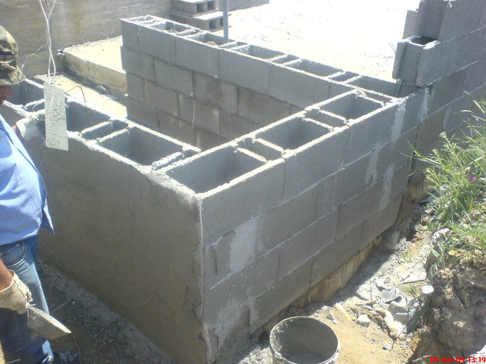
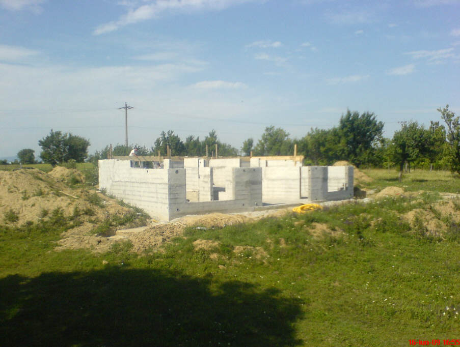
In the picture just below you can see the
excavation and the steel rebar for future
foundation. Under this foundation , on each corner of each room there is a cube
of steel reinforced concrete.
Actually, these 12 cubes are the real foundation.
This
was necessary because the soil is sand and gravel -- the shore of an old
small drained river (the river was diverted 70 years ago when the railway was built).
The walls will be heavy concrete blocks filled with steel reinforced concrete,
and needed good support.
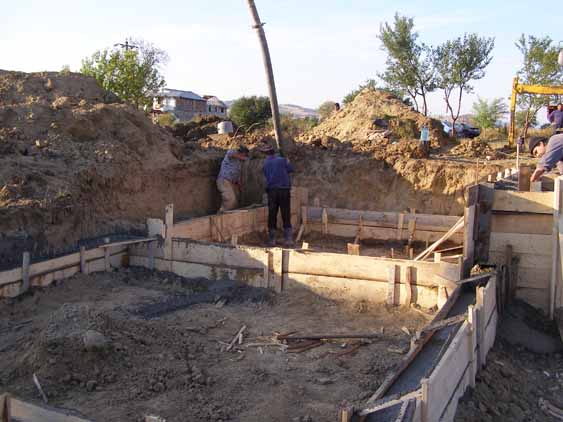
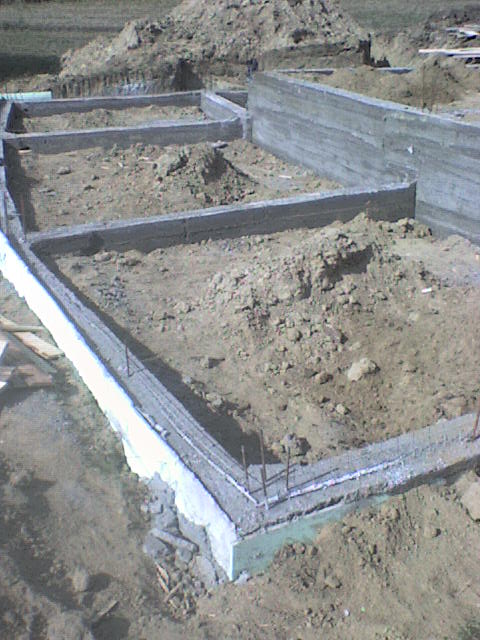
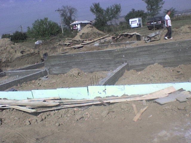
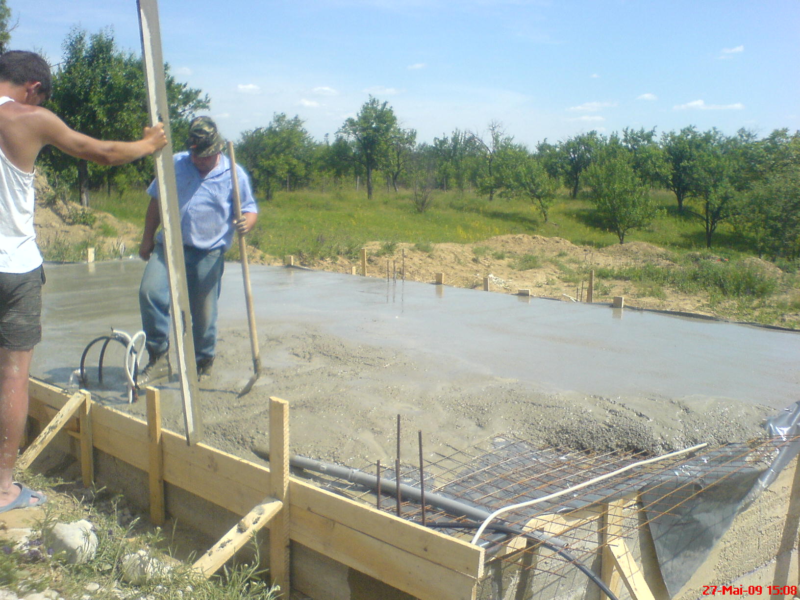
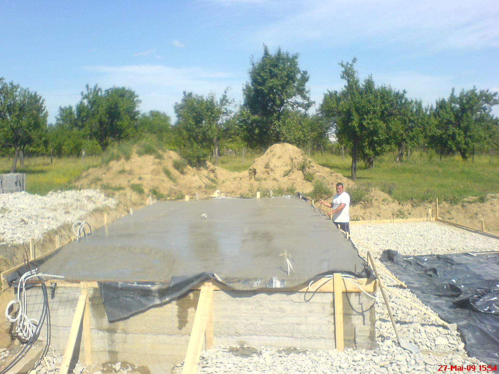
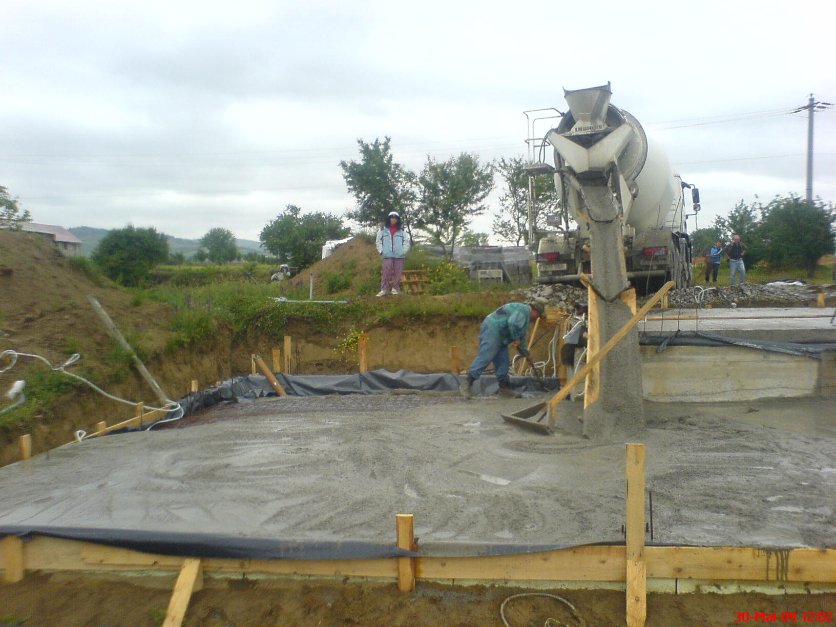
The foundation preparation and pour.
The pictures above show the completed foundation.
Extruded
polystyrene insulation was used on South wall, since it would not be buried.
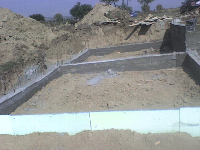
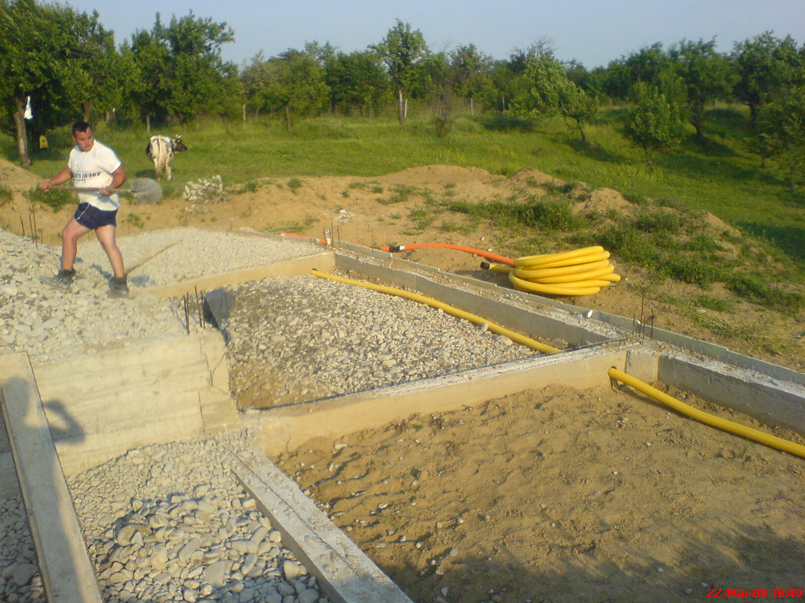
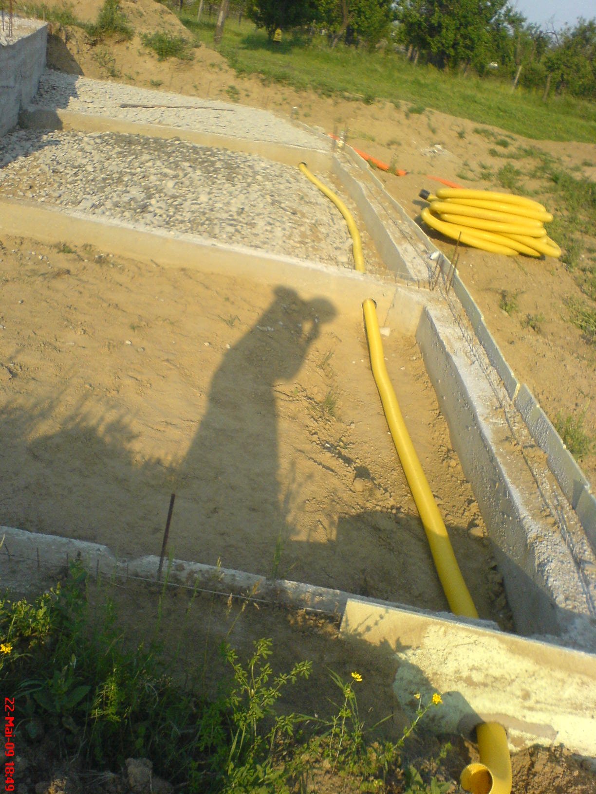
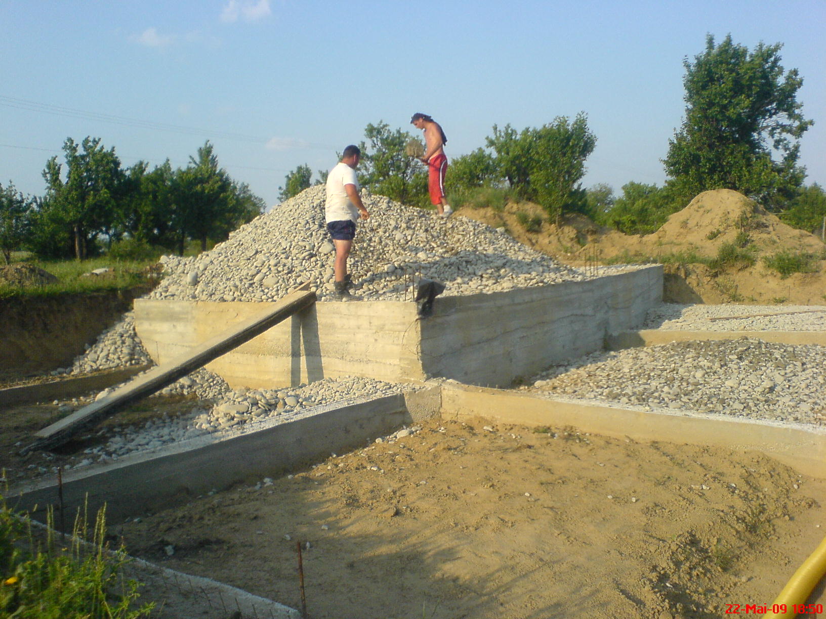
These pictures show placing gravel
between foundation lines.
Notice the yellow and orange tubes (blue lines in blueprint) used to extract bad
air from inside.
Orange tube have a branch that will continue vertically thru the wall.
Passing the stale but warm air
through the gravel under the slab recovers some of the heat in the air.
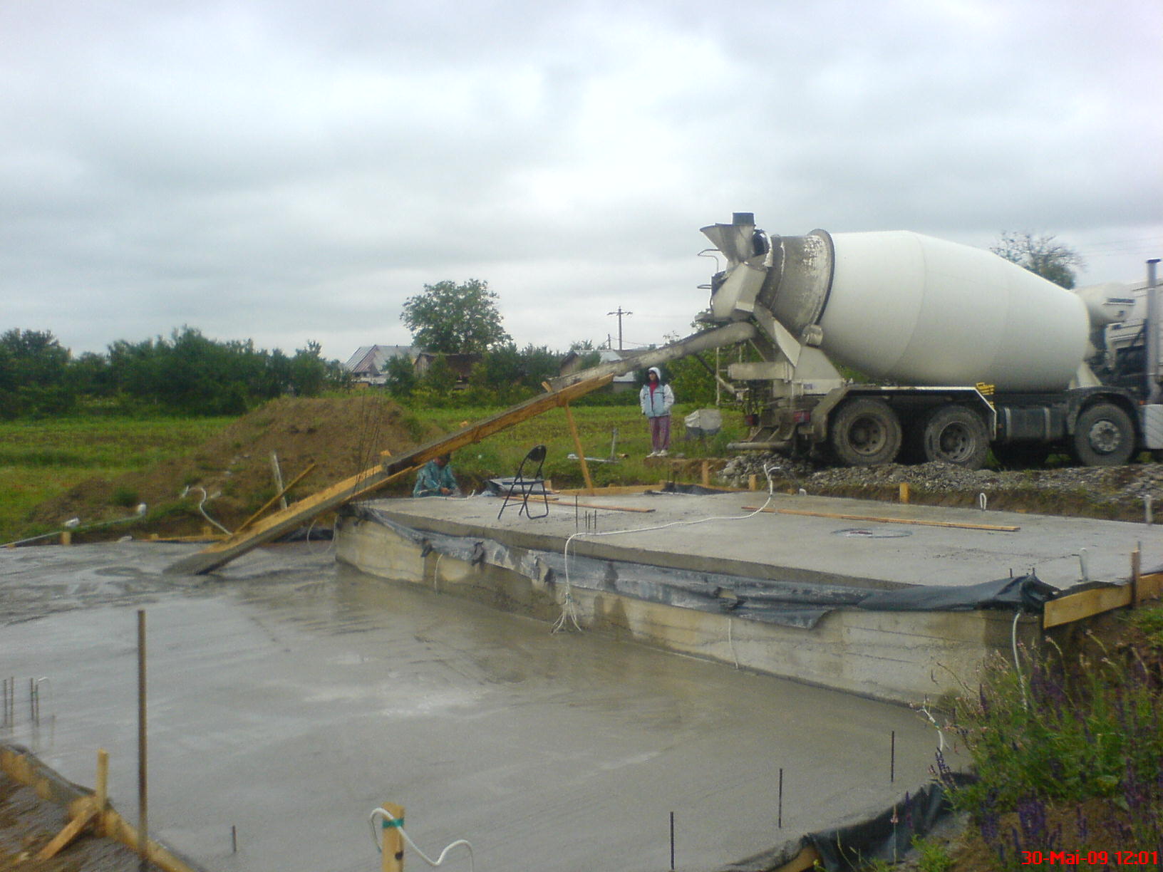
Pouring the floor concrete. Plumbing and electrical outlets are
fixed in concrete.
Note the steel bars coming from foundation on each room corner and
on the middle of the future walls -- these will tie into the block walls.
|
This picture shows the technical basement,
which is used for plumbing distribution.
This room is in the NW
side, below the small bathroom and main entrance.
The level of this room is
1.8meter (6 ft) below the lowest level of the floor .
|
 |
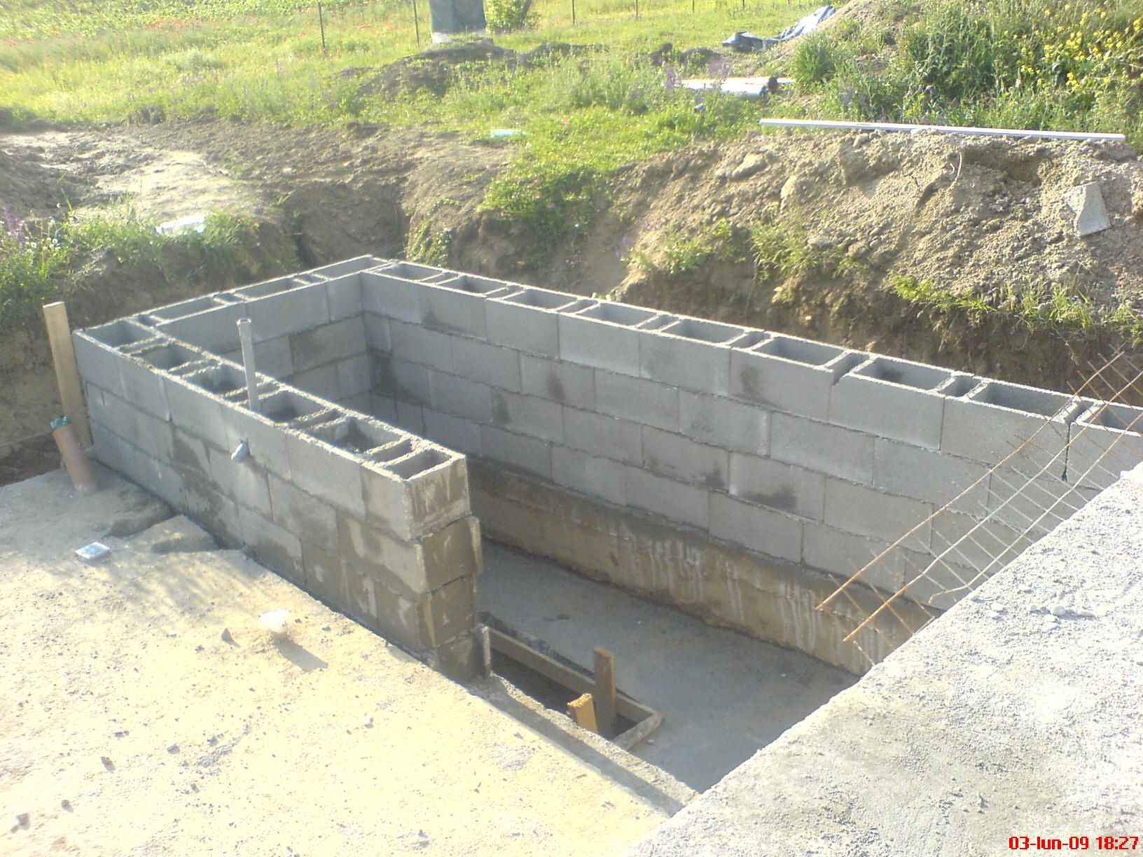
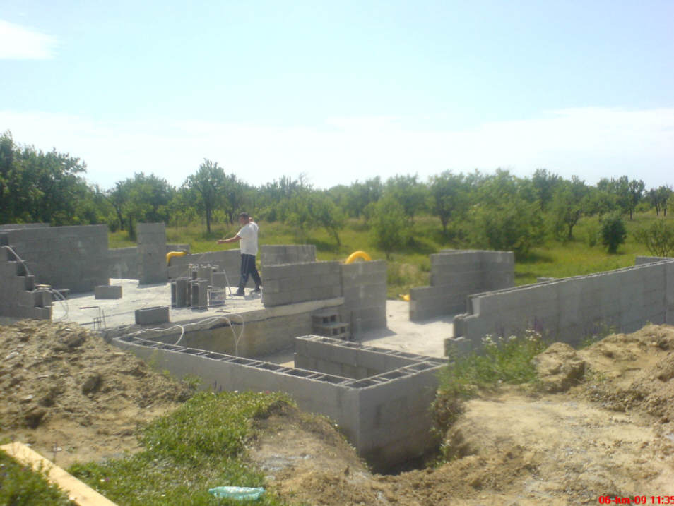
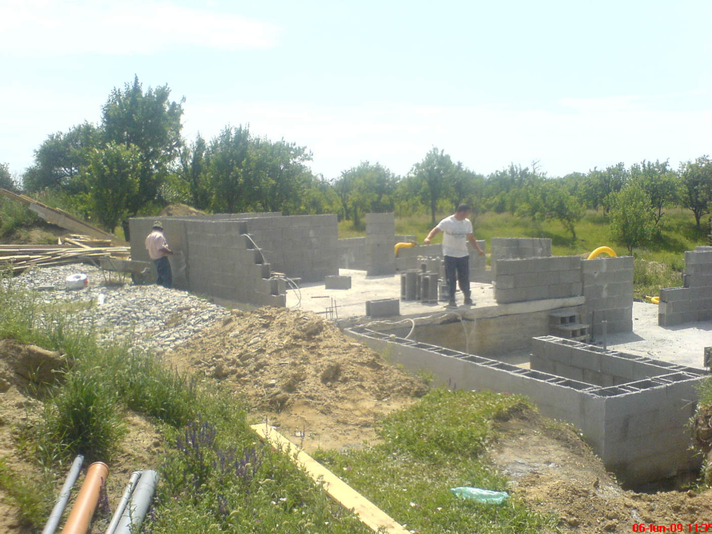
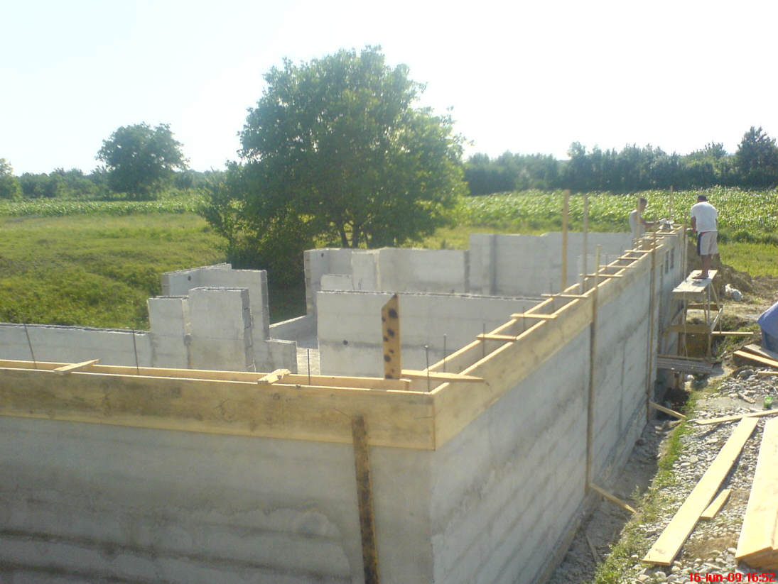
Building the Walls
Building the walls with reinforced concrete blocks.
Every two rows of concrete
blocks, I placed two horizontal steel bars.
Every two concrete blocks we put a
vertical steel bar except the corners where are four steel bars.
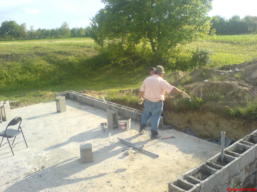
The workers are
locals who had never built a house like this. Everyone ( except my wife), including
architects and construction engineers told me that I was crazy to invest my money
in an underground house.
I lost the pictures of drilling the walls and mounting the boxes for
the electric outlets and switches (0.08meter in diameter).
Flexible tubes
with electric wires were fixed in these boxes. The cables for the outlets where
already there in the floor. For the switches they go up to the top of
the walls.
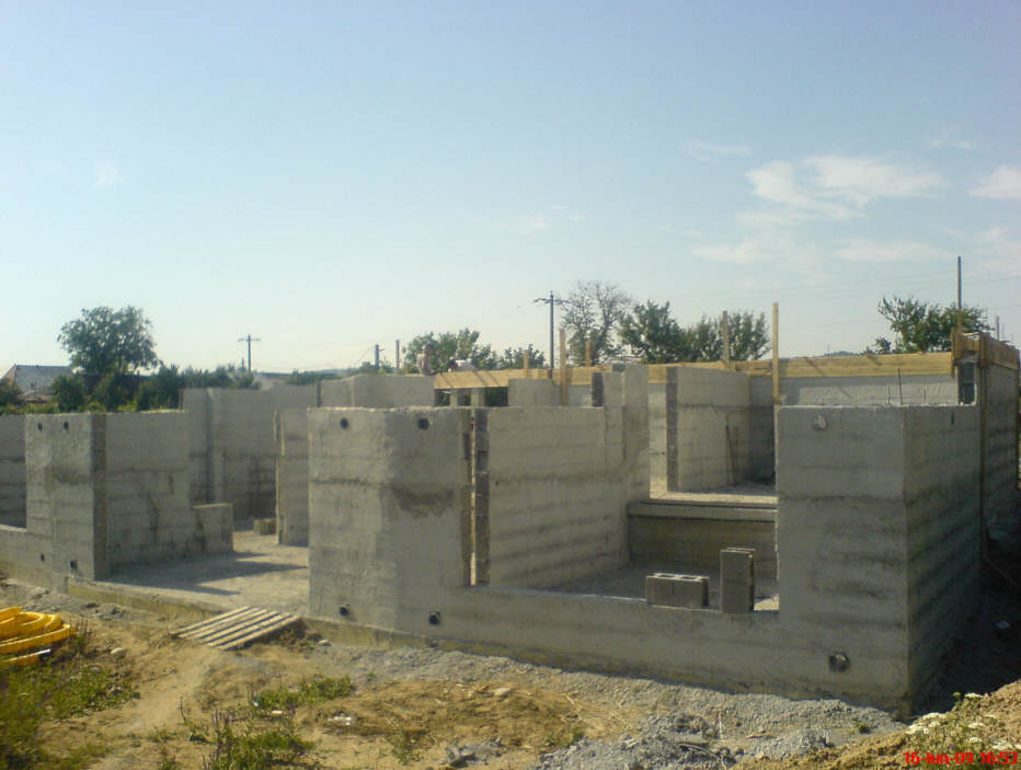
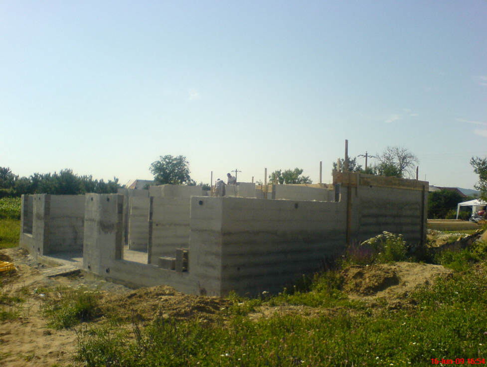
Please notice, on South walls, the
twelve big drilled holes (6 up and 6 down).
Each pair of holes ( with a tube inside) will be used to circulate air to a 1x2meter
Trombe wall.
Each of the three rooms on South side have two
Trombe walls. Each bedroom has an earth tube hole in the external wall.
The walls were plastered
with very strong waterproof plaster and fiber glass net After all electric wires
and plumbing tubes was in place, I placed the vertical steel bars and poured concrete in
walls.
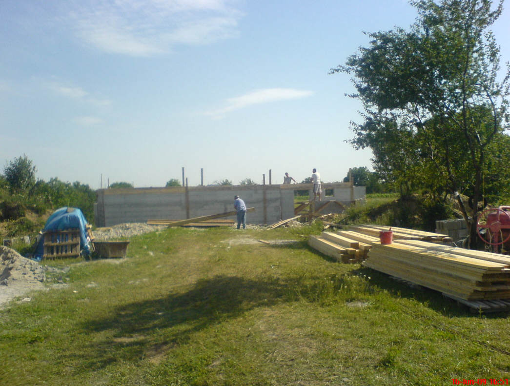
Building the wooden mould for the top concrete "belt". This
steel reinforced "belt" will copy the foundation on the top of the walls for a
stronger 3D structure.
Before pouring concrete I mounted, inside the mould,
electrical "boxes" with flexible tubes with wires to distribute power to switches and
lamps from general electric box.
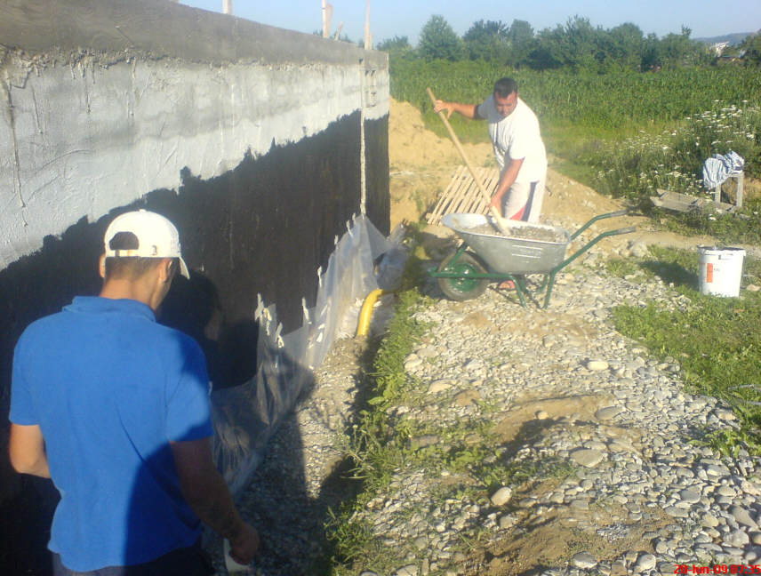
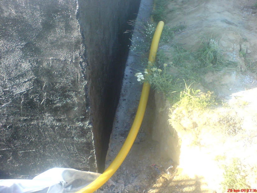
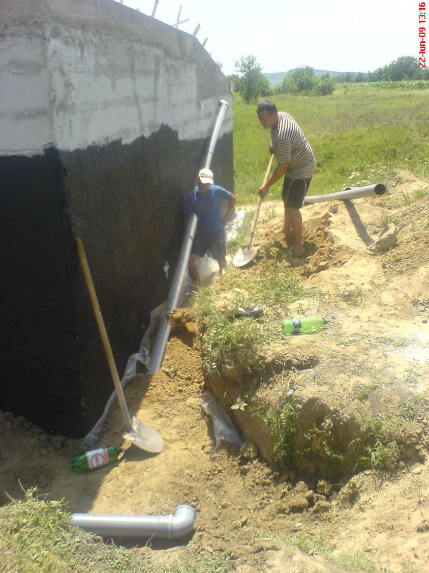
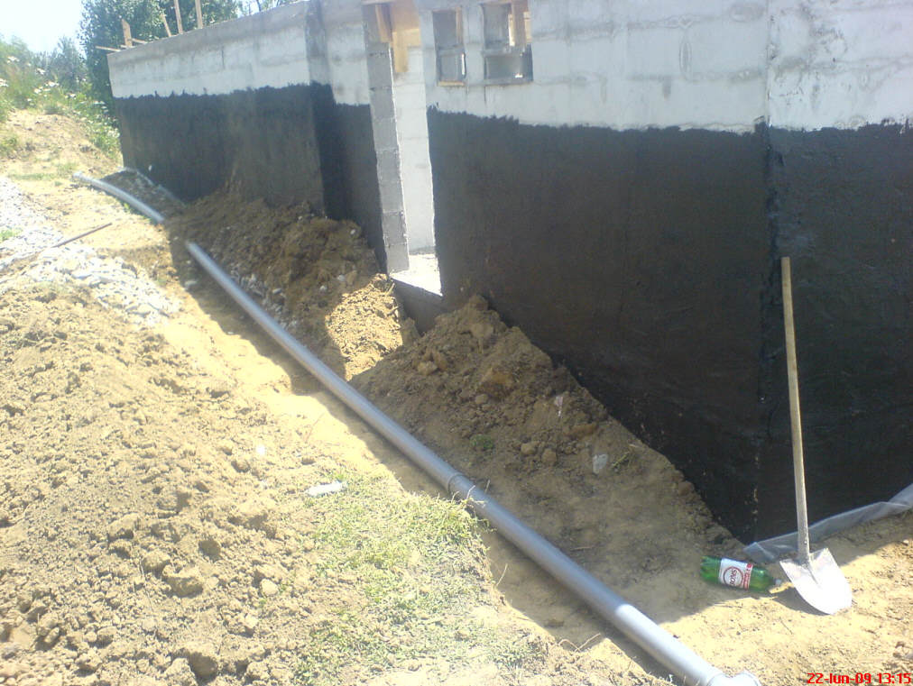
Foundation Drainage
After water proofing the external walls (special black "paint") its
time for foundation drainage.
First the Polyethylene film, then special tube
buried in gravel.
Earth Tube Ventilation
Installing the earth tubes for fresh air ventilation. The incoming
air was heated to 16C by its passage through the tubes when the temperature
outside was -10C. Even though I am a heavy smoker,
the air inside is fresh (not always in the evening but completely odorless in
the morning).
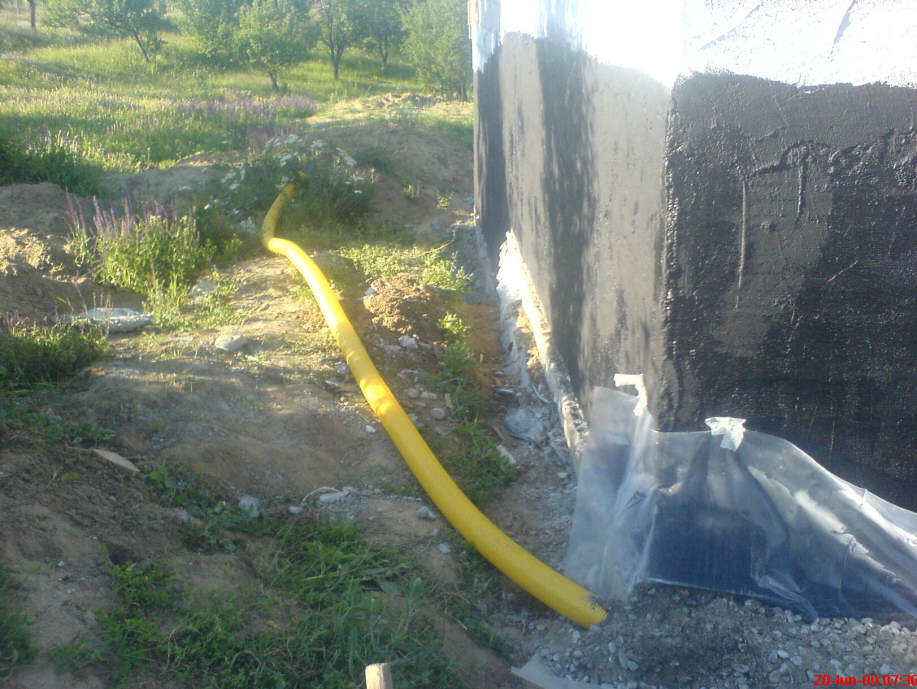
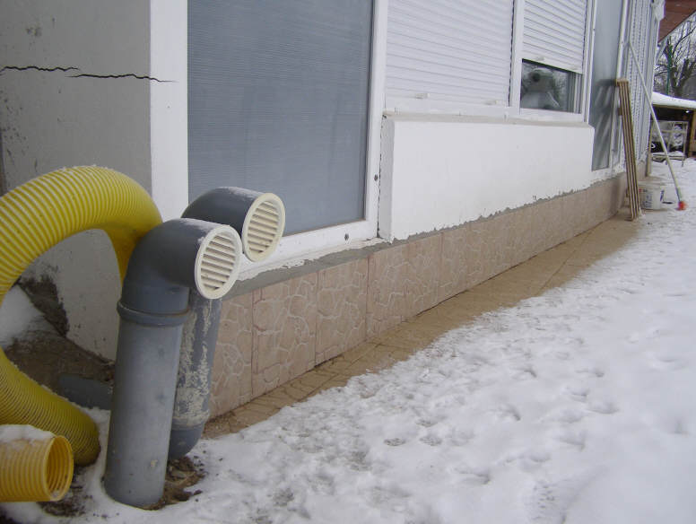
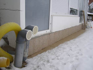
| In this picture you see (near
the outside earth tubes exits) two yellow drainage tubes --one
comes from under the house and the other one goes around the house, near
foundation. This is the right side from the plan where the solar
collector will be.
On the other side of the deck is the small solar house ( near the
barbeque). This circuit is a little bit complicated (twice wrapping the
house and twice reheated) but this air is always warmer then outside
winter air. The blowers are controlled with an egg incubator
thermostat located inside solar house. |
 |
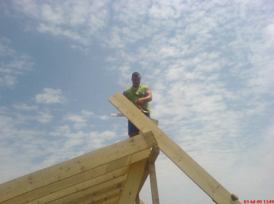
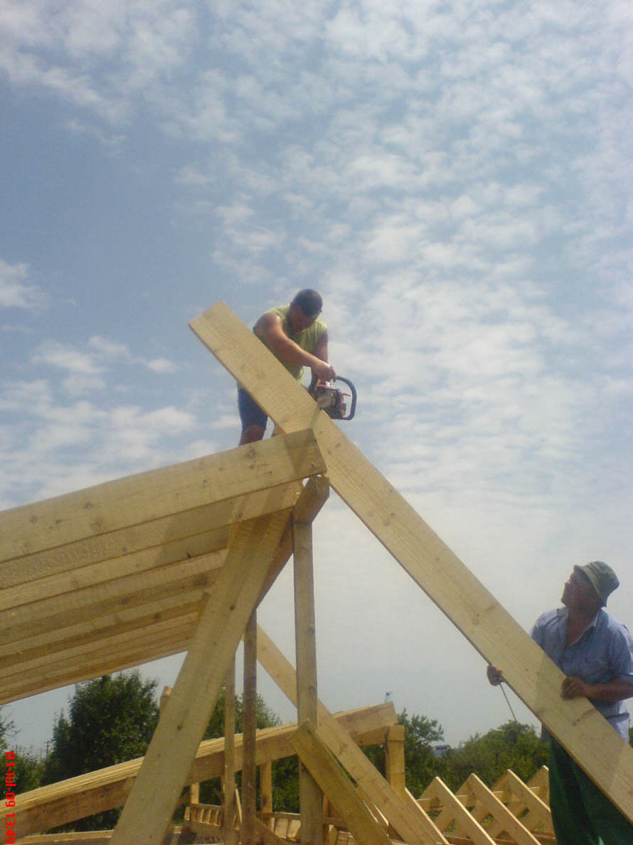
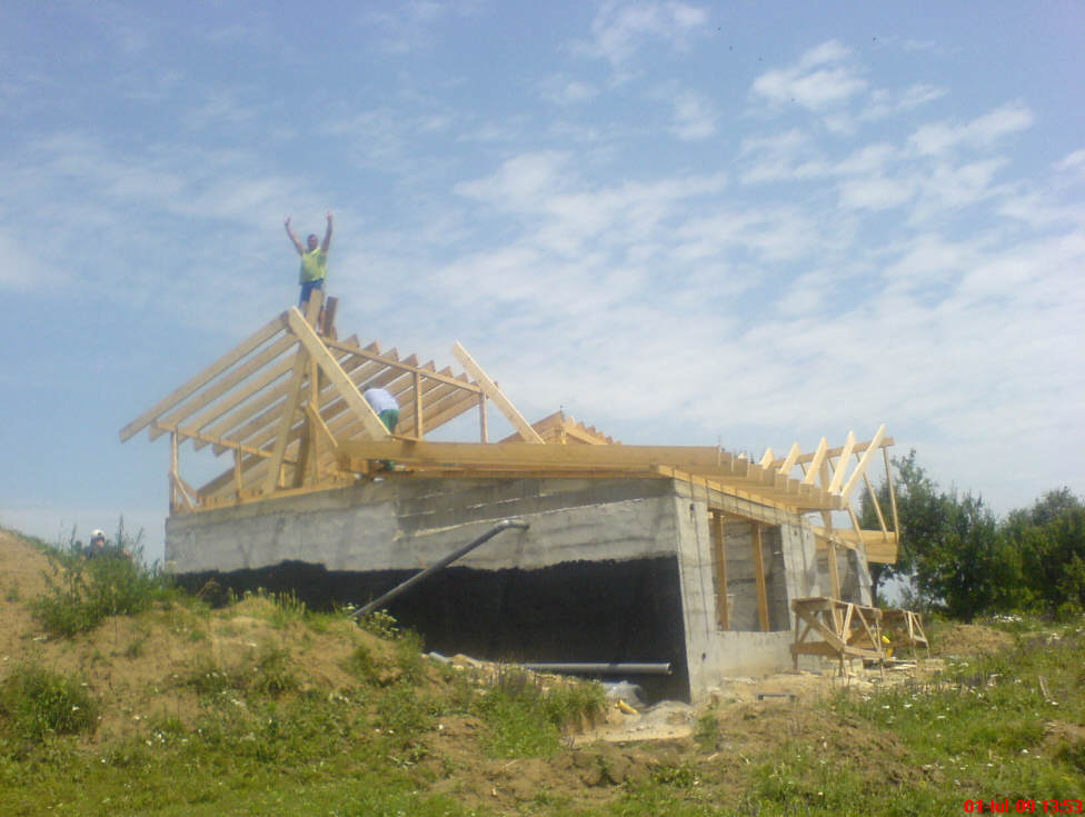
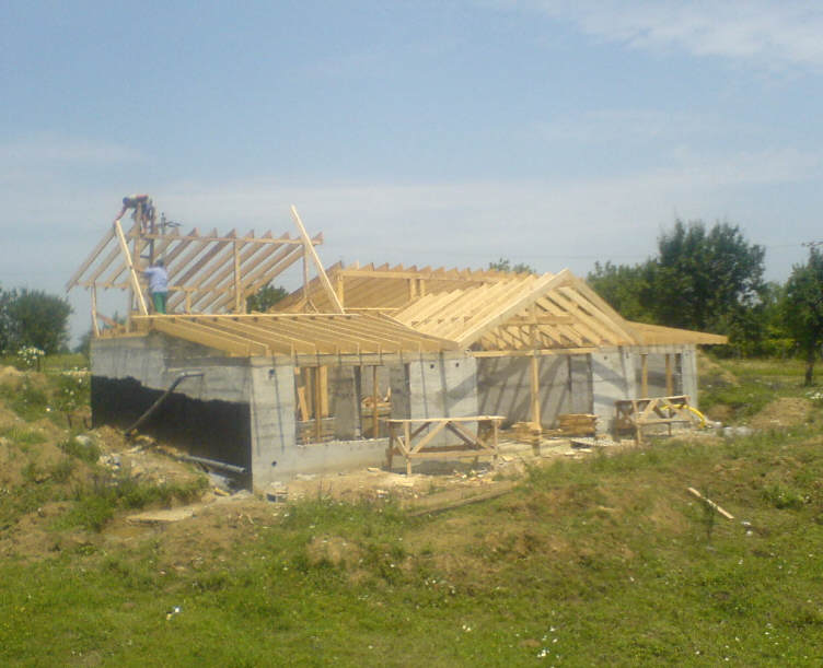
Building the Roof
Erecting the roof. Inside wooden frame I put 0.2m
(7.8 inches) of polystyrene
an 0.05m (2 inches) of mineral wool with aluminum foil.
The polystyrene blocks that fit
between the roof rafters are cut so that they are a friction fit.
|
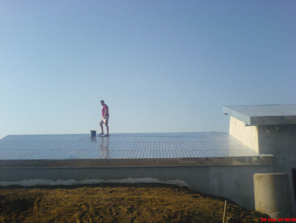
The roof was covered with wooden panels, asphalt foil, special
polyethylene
film and finally with corrugated, galvanized steel.
Galvanized steel is the best
solution, because in summer time will reflect the sun rays, keeping cool air
inside ( there is no attic to provide isolation).
The workers installed the corrugated steel
at night because during day time they can be blinded and cooked in 5
minutes.
|
 |
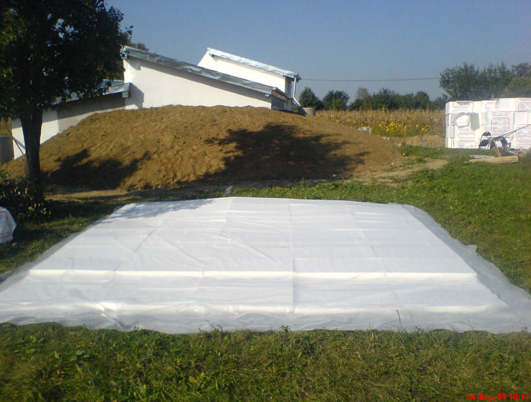
All of the excavated earth was used to build a hill
around the house (except for the South wall). The exposed part of the walls were insulated with 0.1m
(4 inches) polystyrene . The insulation extends for 0.5m (20 inches) under the earth line.
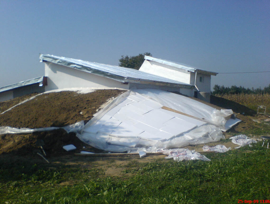
Big "blankets" of
polyethylene and 0.1m
(4 inch) polystyrene blocks were assembled on plane ground and then pulled over the hill.
Polyethylene was sewed around to keep
polystyrene blocks well joined inside. The
blankets were covered with small squares of cut earth with grass.
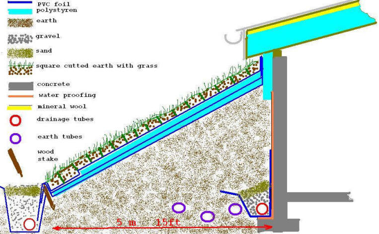
Diagram showing the berming, insulation, waterproofing and drainage scheme.
It was impossible to throw earth with the shovel over
polyethylene. This summer I will
add over an extra 0.2m (8 inch) blanket of earth, because, now, there is not
enough earth to
keep the grass alive.
The South and North Faces
The south glazing.
All windows are triple glass and have exterior shutters
(extra isolation on winter night).
Trombe walls are covered with double
polycarbonate glass. I will change polycarbonate with double glass because:
a) It is not transparent as glass -- the concrete wall is heated only up to 35C-38C
in sunny winter days.
b) It is not as good an insulator as double glass, so
there is more heat lost in cold winter nights.
c) Static electricity glues dust inside,
which makes the glazing more opaque to the sun's rays.
d) The
polycarbonate will be reused for a small glass house where can be bent to be stronger in
"ice rain" or wind case.
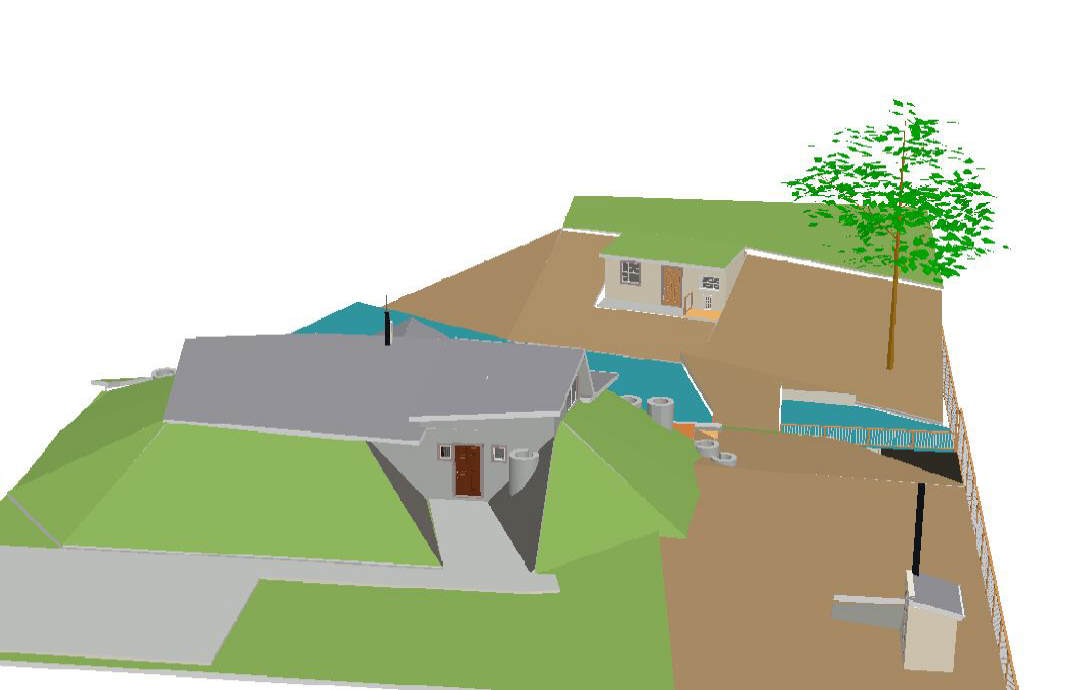
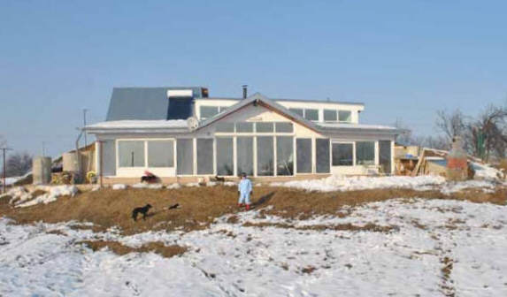
View from the North.
This is what you see from North.
Normally this view from the road is considered the front facade in Romania
and is made the most beautiful.
Not in my case -- I prefer to see nature, which is
refreshing and beautiful in all seasons.
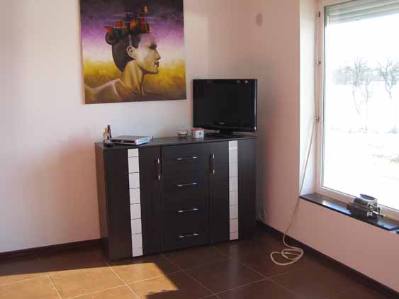
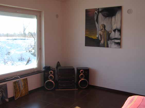
The Interior
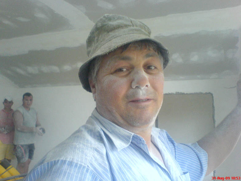
Inside walls were plastered and
ceilings were covered with gypsum boards. A dusty job.
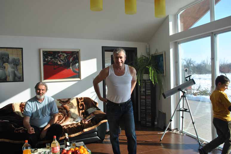
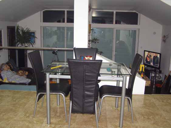
Interior views taken January of 2011
with no fire going.
The guy with white beard is me.
My friend wants this picture
to remember how hot it was inside, without any fire in fireplace!
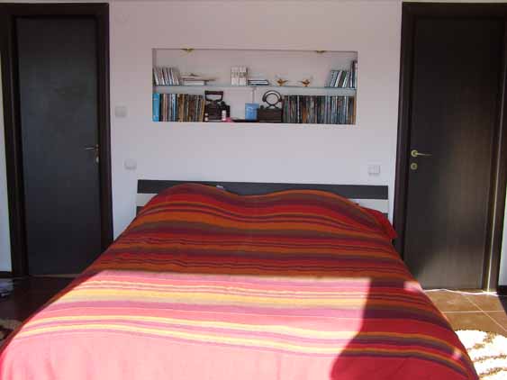
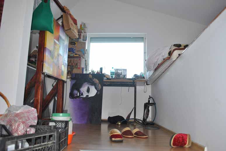
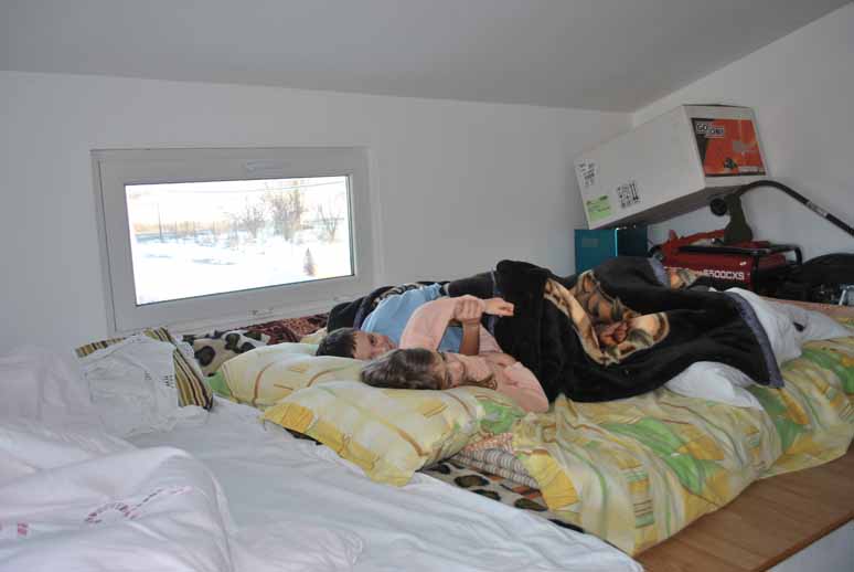
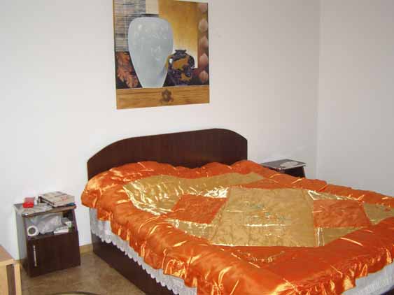
Views of the master bedroom. Notice how far the sun's rays penetrate
the room (pictures
taken on 1st of January).
This is the only room above ground level. The room has 2 levels, the higher level (
above small bathroom and main entrance) is used for storage and, sometimes as a
big bed if we have lots of guests.
The South roof of this room has a 70 degrees slope for the solar water heater and
for future photovoltaic panels. This angle is perfect for winter when I need the highest
solar radiation. All
other roof slopes are about 12 degrees, which is better for a horizontal ceiling
sensation and also keeps the snow in place (as a blanket insulation in the winter).
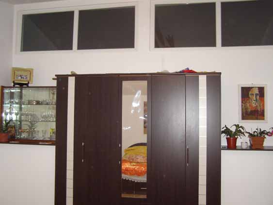
The 3rd bedroom. Between these bedrooms there is a wall made by 3
wardrobes,
one for this one ( in the middle) and two for the other (lower) bedroom.
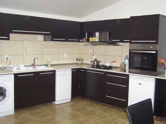
Hihg placed windows are also in kitchen.

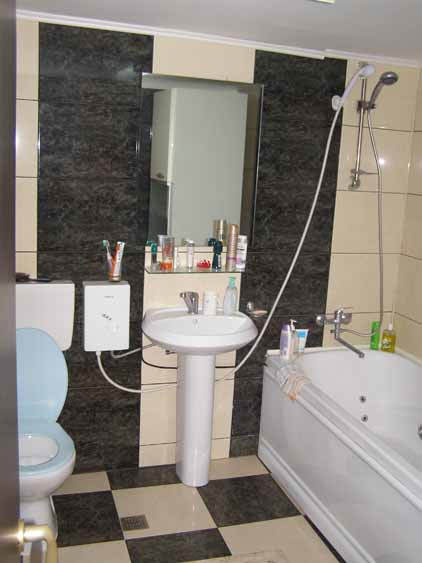
The master bedroom bath. |
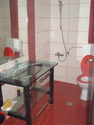
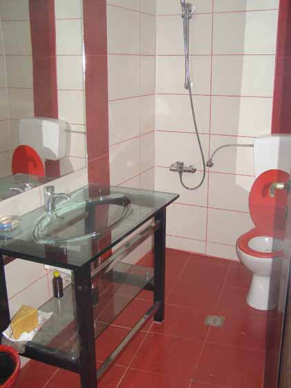
The small bathroom |
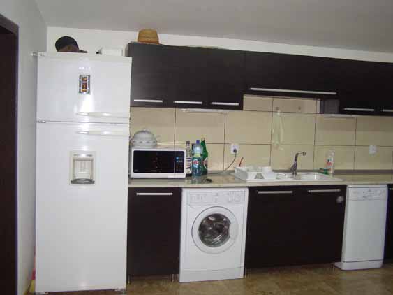
Kitchen and
dining area.
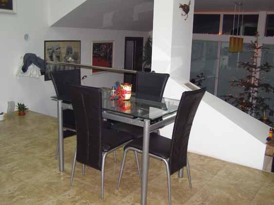
The living room as seen from
kitchen.
The fireplace chimney is attached to the middle column and
is covered
with fire proof gypsum board. A 15 watt blower pushes air from
living room floor,
thru through the box that surrounds the chimney, recovering heat from chimney. The
heated air exits in kitchen near
the ceiling where a big fan pushes it down to distribute it.
The hottest period inside is from late
autumn till early spring (27C - 29C) but usually is from 18C (in the morning) to
23C ( in the afternoon).
From late spring till early autumn the temperature
never exceeds 27C, but usually is between 20C(morning) to 24C(afternoon). When
wood is burned in the fireplace, the air is faster freshened by earth tubes (
you know why).
| |
Cristian adds that if he were to do the house over
again, he would probably make the south window area about 20% smaller, while
increasing the Trombe wall area about 20% to balance out the day and
night temperatures.
Some of the high temperatures noted above were due in part to not being
able to use natural ventilation because the mosquito screening had not
been installed. They also plan to plant some grape vines along the
deck to provide summer shade.Christian also points out that they get
several day periods of several sunny days in a row in the late fall,
winter, and spring. The house heats up to temperatures as high
29C, and it feels great! |
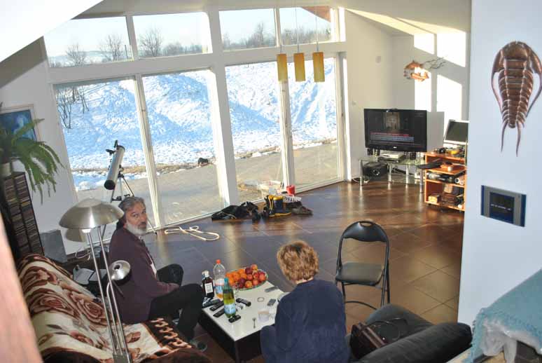
Nice bright interior.
Performance
|
Over the winter, we burned 2
cubic meters (0.6 cords) of wood, which cost $70!
The house is located at 45 degrees
north latitude and has a long and cold winter season.
We have lived in the house for two winters and one summer and the house works
perfectly. Each winter I've used less then $70 for firewood and the temperature inside
the house has been between 17C and 27C.
In this climate, a conventional
construction home with similar
living area, the heating season extends from the middle of September until the
beginning of May
and the cost is at least $300 per month. |
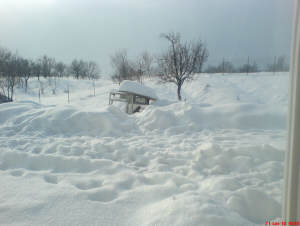
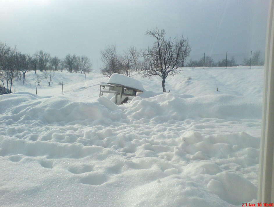
Looking out the window last year |
Finally
I would like to thank my wife
for many good ideas, but mostly for supporting me when everybody said I am crazy
to put our money in such a project.
The next projects are building a
small green house( 2m x 3.5m) and erecting my wind turbine (the 250W generator
is a brushless direct drive motor from a washing machine).
Cristian Paun
March 4, 2011
Be sure to check on
Cristian's new blog on
his home here...
Cristian will answer email questions
on the house at: 
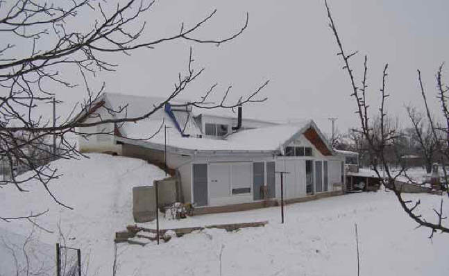
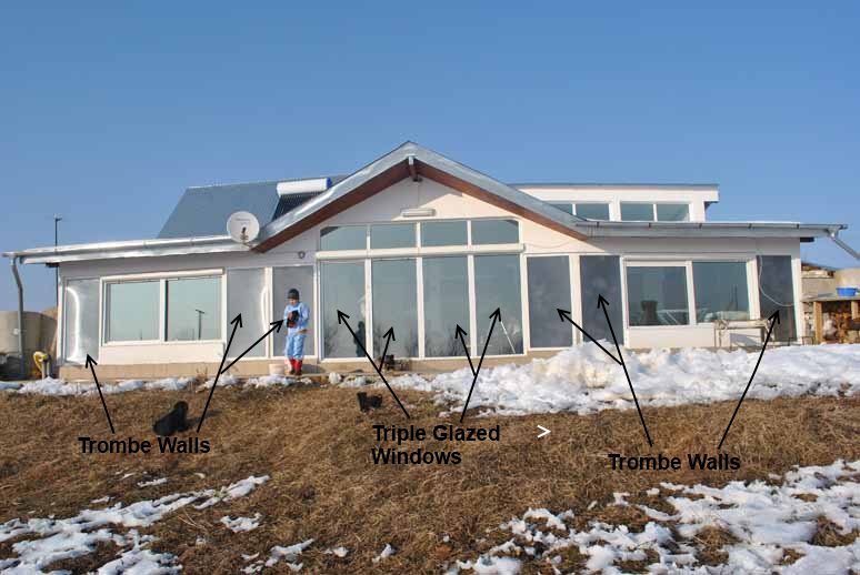
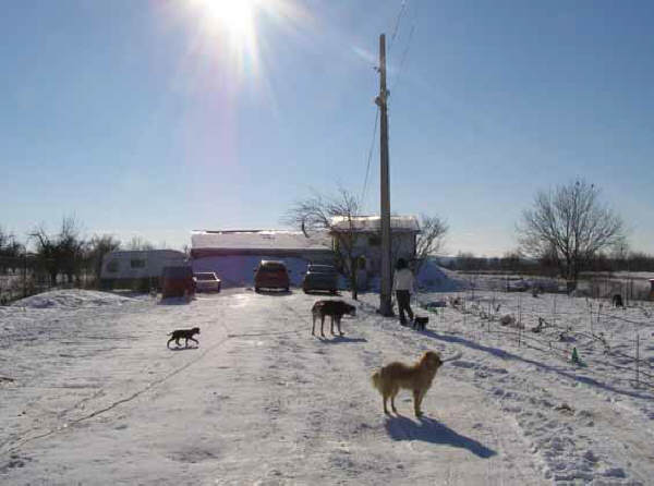
Cristian's home in the winter.
In addition to the great thermal envelope, note the solar water heating and the
rain water collection.
Gary March 16, 2011