This page covers a set 6 of the
copper
pipe/aluminum fin collectors built by Chad for space heating. The
collector design includes a unique hinged mount on the top of the collectors
that allow the collector tilt to be adjusted by season.
In addition, Chad shows an alternative way to build the collector frame.
Thanks very much to Chad for
providing this material!
Gary’s copper – aluminum collector design was used as a
baseline.
It was modified as follows:
The frame was made with the frame members cut to
eliminate the square absorber mounting strips. Square strips were used
under the glazing as per Gary’s design.
I
did not put the 3” aluminum strips under the copper tubes. My testing
showed the aluminum transferred heat to the copper very well without them.
They would help get the heat to the copper from the outside of the aluminum
panels, as the aluminum path is quite long. As copper has dropped to 50% of
what I paid for the first panel, the final 3 panels I assemble will use 9
vertical copper tubes with 5.5” wide absorber strips.
I
double glazed the collectors. I calculated the R value from the aluminum to
the front of the glazing to be 2.3. The second layer increases this by 1.6,
a significant improvement. The payback is positive when the air to water
delta is above 40-60 degrees, with it making a bigger improvement at lower
power output levels.
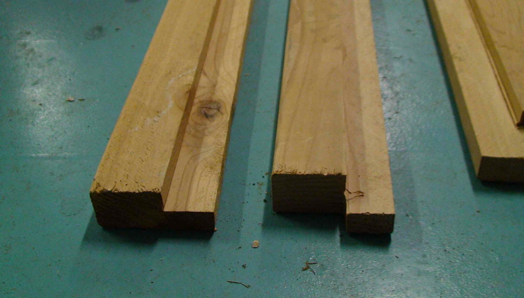
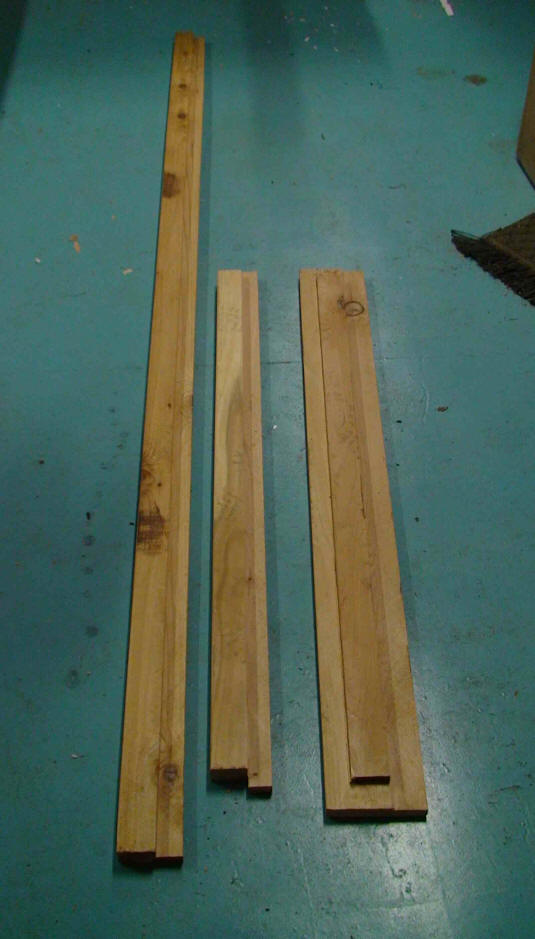
Frame
Pictures of the collector frame
components -- Click on pictures for full size -
From left -- side rail, bottom,
and top
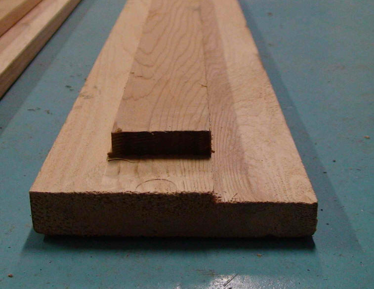
Top 2X6
The frame members can be cut easily and quickly if
you have a table saw.
Save the waste from the 2x4’s for the side glazing
strips and top and bottom hold down strips.
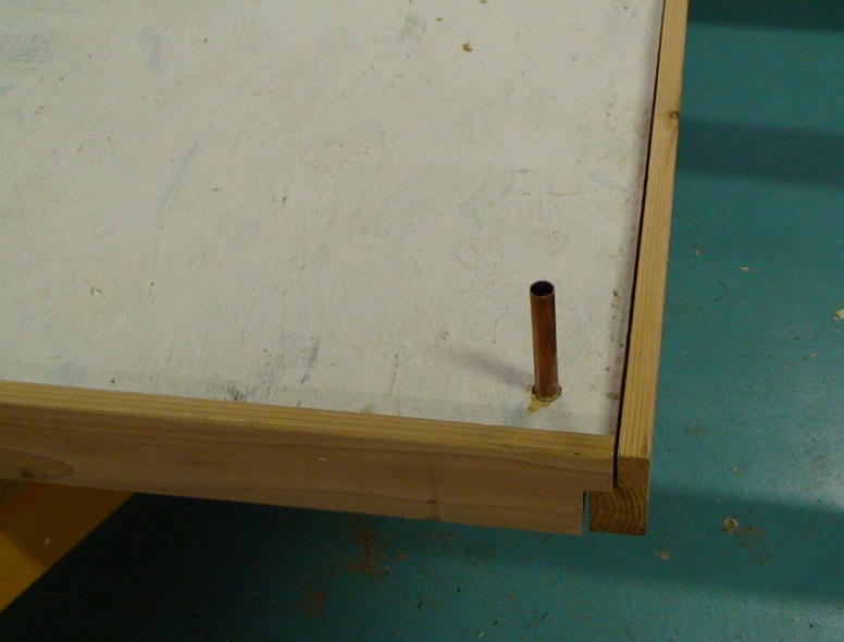
Pre-drill the conduit holes, at 1/3 and 2/3 way, at the top edge ( the 1.5” wide
part). Drill ¾ way through the wood. The holes are not detailed in the drawings.
To assemble the frame, I put the absorbers aluminum
down and spaced them up 1 ½ inches. The 4 pieces were placed around the absorber
so that the absorber was resting on the notch. The conduit was placed in the
holes at this time. Next, the corners were drilled and screwed. After the frame
was secure, the absorber was screwed to the frame at 5-7 spots for each frame
member. Next, insulation was cut / drilled to fit and secured with expanding
foam.
Click on pictures for full size
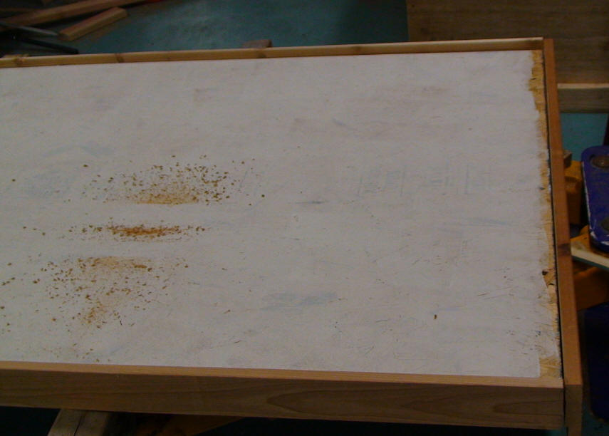
Absorber panel viewed from back side
and placed inside the 2X4 frame.
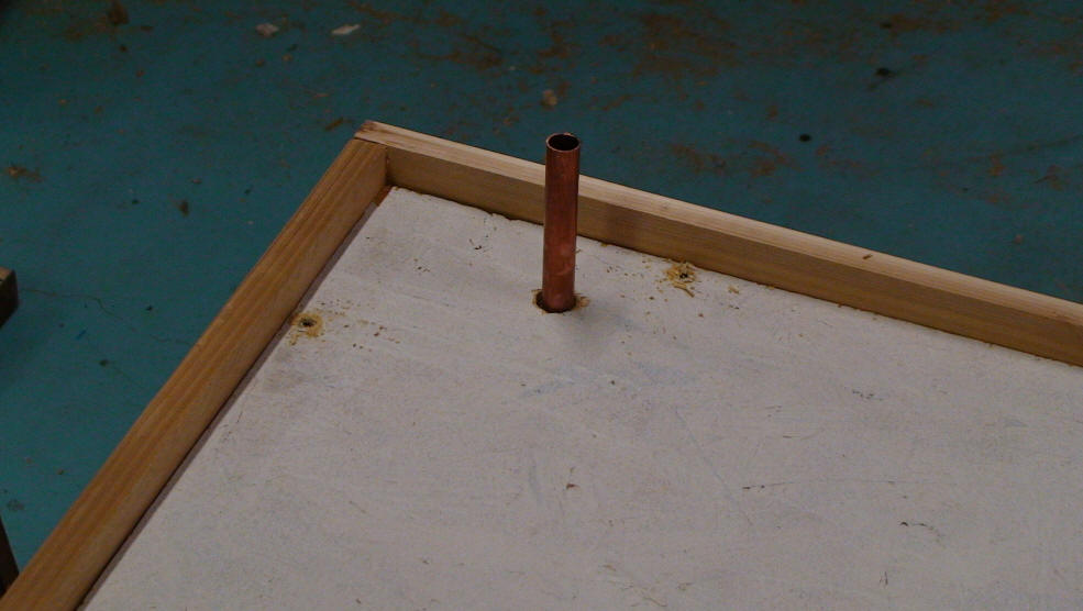
Backside of absorber panel.
Supply and return lines penetrate
the absorber panel.
Clamping up the absorber and
frame before screwing absorber
to frame.
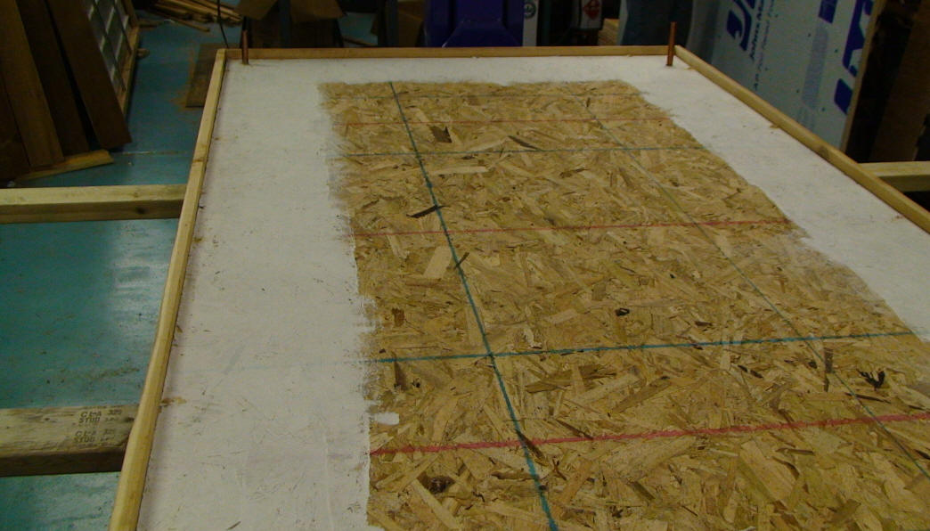
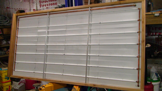
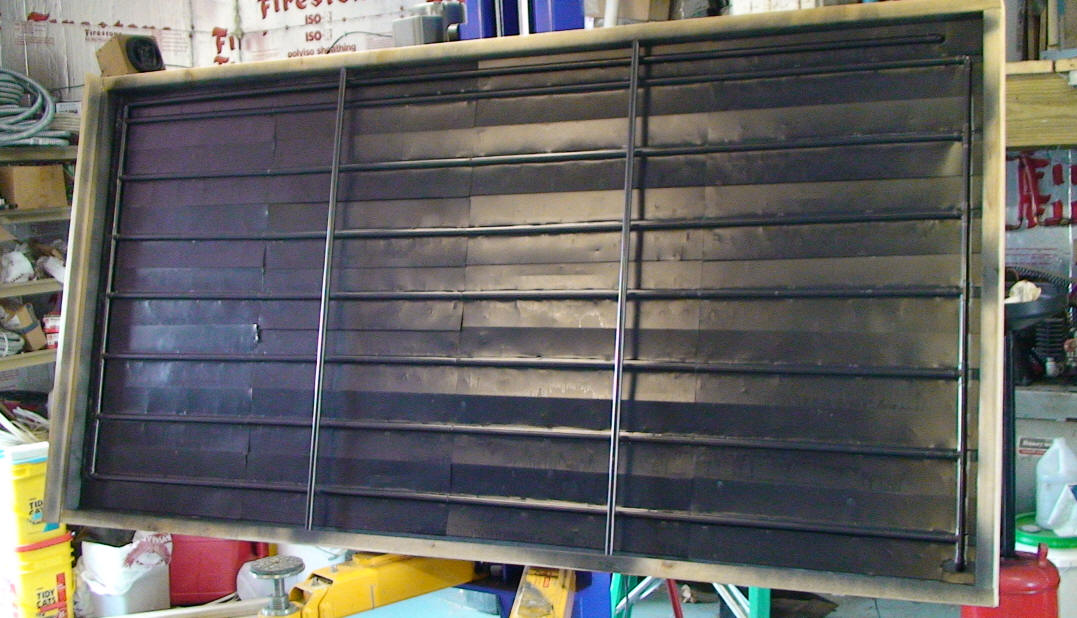
The collector frame with the copper pipe grid and
absorber fins ready for painting.
Glazing
The two sheets of polycarbonate that form the inner layer of glazing layer were not
siliconed together as I didn’t see much benefit in doing
so. It was placed on the absorber after putting a silicone bead on the conduit.
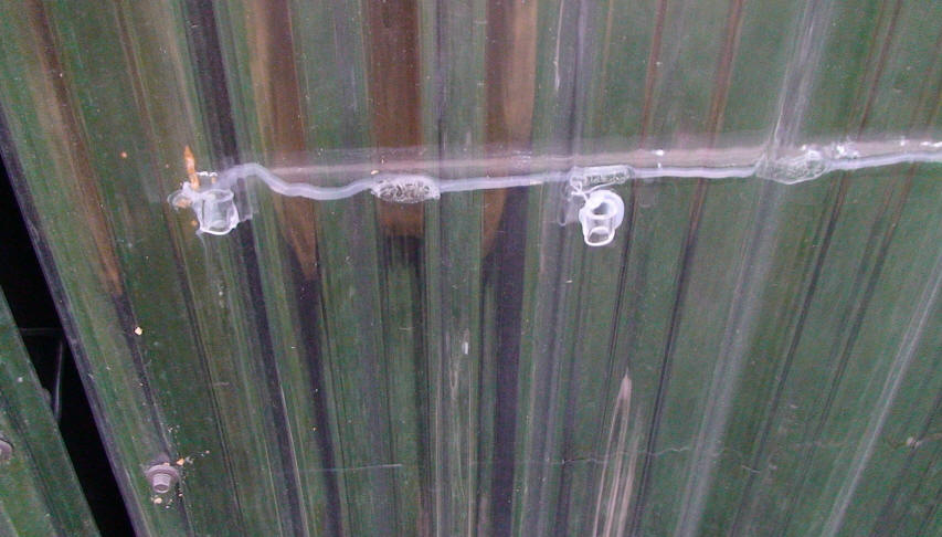
To separate the two layers, I cut ½” pieces of ¼” vinyl tube. I placed these
about 4” from the top and bottom and every 10” across. They were secured to the
inner glazing by a dab of silicone. I placed a piece every 12 inches on the
sides, one rib from the edge. I then scattered them on the rest of the surface.
In reality, I put down more separators than needed. The outside layer tends to
bow out due to expansion and separate from the inside. They were secured in the
same manner as Gary’s. When drilling, ensure wood particles do not make in
between the 2 layers.
Vinyl tubes that separate
the two layers of glazing.
The tubing runs parallel to the glazing ribs.
Drawings -- click on picture to view
dimensioned drawings for the collector... (pdf files)
The Collector Assembly
2X4 Side Rails
2X6 Top Rail
2X4 Bottom Rail
Plywood Back
Back Insulation
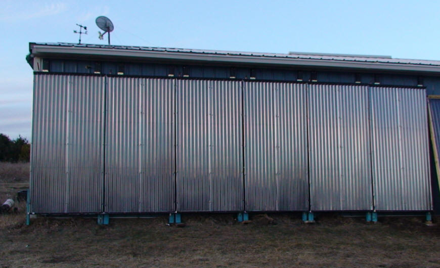
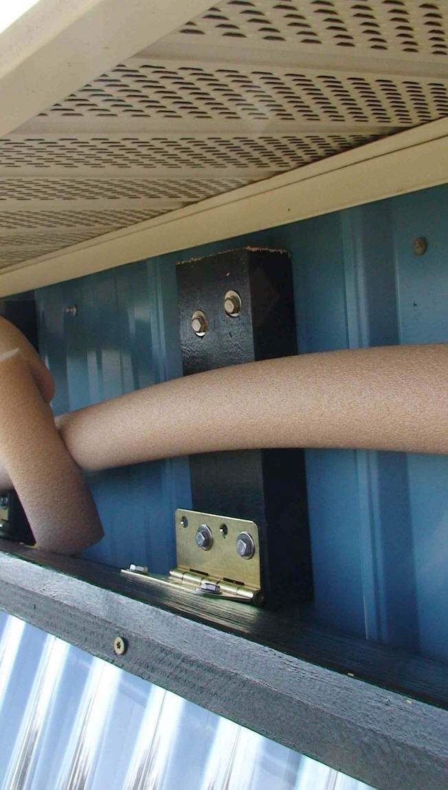
Variable Tilt Hinge Mount
The ridged siding used on my shop and
the general design of a pole barn complicated mounting the collectors. There are
3 horizontal 2x8 pieces under the steel siding. There are also vertical 6 x 8”
posts every 10’. I preferred to be able to change the collector angle as needed.
I ended up with the mounting detailed here. I used stainless lag bolts to secure
door hinges to the collectors. Corrosion resistant fasteners are supposed to be
used with the new treated lumber. I mounted the hinges to the collectors,
positioning each to avoid the ridges in the steel. The attached 2x4s serve two
purposes: to space the collector off the side and to reach the shed 2x8.
Click on pictures for full size
Water Lines:
For the hinge mount collector, I ran
the copper lines out the top and bottom. To ensure the top line will not
interfere with the wall at maximum tilt, I used a 45 degree fitting at the top
of the collector to provide more than enough tilt.
The variable hinge mount requires
flexible water lines. Multiple options were considered:
CSST (corrugated stainless steel
tubing) natural gas tubing:
The tubing is reasonably priced. The fittings are $5 each. At 4 fittings per
panel and the mating hardware, this got expensive quickly. The corrugated
tubing will also decrease fluid flow. CSST is not supposed to be used for
flexible gas installations. I suspect it will work harden after many flexes.
Hydraulic Hose:
I did not know if this would prevent oxygen from entering or not. It is
probably more expensive than CSST, should take the temperatures and
definitely the pressure from the system.
PEX:
This is the cheap and easy to install. The downside is possible thermal
expansion, overheating, and sun exposure. The PEX is presently covered with
pipe insulation to insulate and keep the sun away. The panel to panel PEX
may be replaced with copper pipe to increase flow and decrease expansion
movement.
Antifreeze
The system is a closed system with
semi drain back capability, that is most of the coolant will drain back to the
house (200’ away). Some of the lines will probably retain coolant. I will have 2
tanks: one in the basement to collect solution and one in the shop ceiling to
hold the gas (argon / CO2) than fills the collectors during drainback. I plan to
use a small air compressor to charge the basement tank sufficiently to fill the
lines when heat is available and a air solenoid valve to discharge it.
I used a 45% solution of Noble Company’s NoBurst HD with 55% distilled water.
This is a very concentrated propylene glycol fluid. It ran $140 / 5 gal bucket
to my door. This will provide for fluid flow capability to below –15 F. Note,
this is thicker than motor oil, so pre-mix it before putting it in the system.
After the system was detergent cleaned, rinsed, and emptied, I used an a/c
vacuum pump to evacuate the air. I then connected a hose to the system and let
it suck water and coolant into it. A small pump was used to pump the final bit
into the system to pressurize it.
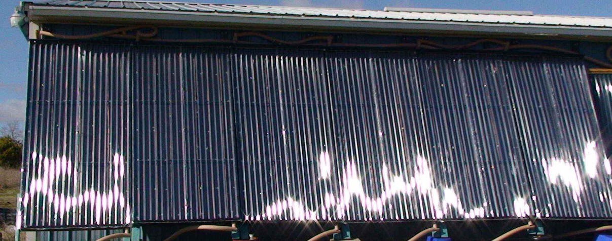
The pictures show the details of the
hinged collector mount along the top of the collectors that allow the collector
tilt to be adjusted by season.
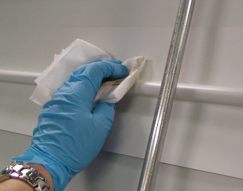
Applying SolKote Selective Absorber
Finish
Chad painted the absorber with a
selective coating called Solkote. The advantage of this material is that
it is a selective finish, meaning that it absorbers visible light very well, but
also has a low emissivity in the infrared so that it does not radiate (lose)
heat as much as a conventional paint. It is also a good, high temperature
finish that will hold up to the high temperatures inside the collector.
SolKote's low emissivity depends on it
being applied by a sprayer in a very thin coat.
Absorber ready for Solkote
Cleaning prior to painting with
Solkote
After Solkote has been sprayed
This was the first time really using
a paint sprayer for anything that mattered. The paint is very thin, it is xylene
based, which seems to be a little less volatile than lacquer thinner. It seems
like they took powder carbon and mixed with the solvents ... probably not that
simple.
SolKote wanted it applied to bare aluminum as this helps the emissivity, (not
practical) and they were concerned about if it would react with the paint. I
tested the reaction by soaking a rag in xylene and sealing to the al for a few
days. It mildly softened the paint and one could then scrape it easily, but once
dry there was no damage.
I used an cheap automotive HVLP gravity feed gun from Harbor Freight at < 40
PSI. I did it in my 30 x 50 ft workshop in early January. Turned off the oil
furnace for a few days then shot them. I did use a chemical respirator but with
good ventilation don't think it would be necessary. We will see by end of next
week on this theory.
I basically sprayed the stuff to cover the white AL. It was quite easy I used
0.019 white roofing coils. There were some runs, but it is good enough. It
was mostly done in 1 pass. I did not measure the thickness. Don't have equipment
to do at home, maybe machinists at work could ...
I shot 6 of the 4x8 panels. That took 1/4 to 1/3 of the gallon. There was no
visible fog and minimal overspray. Fumes were not overpowering. All 6 took < 50
minutes with 1/2 of that probably refilling the gun and making space. I adjusted
the gun to give a even coat over 4-7 inches and held it at less than 1 ft.
I closed up shop and came back a day later. There was little if any smell left.
The shop is quite tight and well insulated so I was surprised.
The paint was 69 + 22 shipping for a gallon.
Note that the SolKote may not be
selective when sprayed over a painted surface, so bear this in mind if
you want to have a selective coating on the absorber -- best to use it
over bare aluminum.
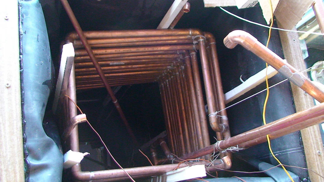
Heat Exchanger for Domestic Hot Water
Chad did a copper heat exchanger using 2 parallel runs of 3/4 inch copper
pipe hooked up in parallel.
click on pictures for full size
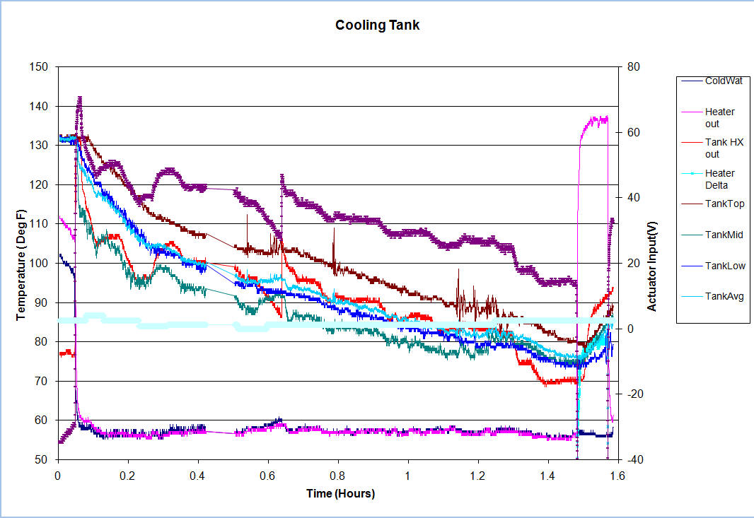
Chad did a test run with this heat exchanger --
click the thumbnail below for a full size plot.
Test Steps
1) The water heater inlet was connected to the shop water supply.
2) the tank was filled with 135 degree water from a nat gas instant
water heater.
3) The heater was turned off, the heater outlet was connected to the
tank heat exchanger inlet.
4) The water was turned on at 0.04 hours to 2.4 gpm.
5) At 0.11 hours the water was turned on full, 4 GPM.
6) At 0.16 hours the water was set to 2.4 GPM
7) At 0.21hours the water was set to 0.875 GPM
8) At 0.21hours the water was set to 0.875 GPM
9) At 0.39hours the water was set to 1.2 GPM
10) At 0.39hours the water was measured at 1.325 GPM
11) At 1.25 hours the water was set to 2.4 GPM
12) At 1.45 hours the instant heater was turned on at 140 deg
13) At 1.55 hours the test was stopped.
Note: The top sensor was above the copper for at least 1/3 of the test
and therefore not reading the water at the top of the heat exchanger
The water had a significant amount of stratification!!
Flow was +/- depending on well pressure.
datalogged with an Omega multi channel commercial logger
All using type K thermocouples
Flow measured with a marked bucket and watch
The tank water compartment is
inches
22.75
w
23.75
l
45.75
h
neglecting liner loss and including insulation.
107 gallon gross
Filled to 43 inches.
Heat exchanger is 2 parallel rectangular loops of 3/4" copper, about 15
x 17
18 loops total ( 9 per) spaced 0.375"
SystemDiagram
Refer the PDF plumbing diagram for the system layout. This
may change somewhat as the house side is completed. This is drawn using
electrical schematic software.
See the Excel sheet for a detailed
time log. I averaged about 9 hours per panel. I wasted a bit of time early
remembering how use a table saw and figuring out than a second fence was very
useful for running multiple boards through with the same cuts.
I attempted to make like parts for
all panels with only one setup process per part. This saved considerable setup
time.
I used power tools as much as possible.
Air caulk gun
Circular Saw for cutting all OSB in one pass. Electric stapler
Grinding wheel to debur 5.8” copper pieces
Lift for keeping panels at an appropriate height while working
Power saw for cutting copper
Drill mounted copper debur / deoxidize brushes
Other Notes:
Home Depot could not get the SunTuf or so they claimed. Lowes happily ordered a
similar product for $21 per sheet.
I found the 0.019” thick aluminum in a 2 x 50’ coil. I cut this into 7.5” x 2’
strips using a shear. This took about 20 minutes per roll, or about 8 minutes
per panel. This time is not in the log.
Additions to the System Since May 2009
A Tankless water heater has replaced
a tank heater. This will peak the solar tank output. Unfortunately, it is 25’
from the rest of the system due to exhaust complications. Additional insulation
is needed on the copper pipes to reduce heat loss.
2 tanks were designed and built based off Gary’s design. The hot water tank is
102 gallons, the dimensions are 29x30x48”. The house storage tank is 292
gallons, the dimensions are 3.5’ x 8’ x28” tall.
The hot water tank was a compromise of fitting into an area between the furnace
and a sump pump. I would not suggest the height to width ratio of the hot water
tank for 3 reasons:
1) Waste of liner material. This tank used nearly the same amount of material as
the big tank.
2) Difficulty in installing liner. The liner was formed around a box then
inserting this into the tank. Otherwise the liner would not seat well.
3) Excess surface area leads to increased losses.
The house tank doubles as a dryer stand. The washer is also on the tank, but
this rests on a steel frame than is bolted to the wall and has it’s own feet.
The waster / dryer are front loaders. The added height elevates them to what is
ideal for moving clothes between the two and removal from the dryer.
The house tank is heated by circulation glycol through about 120’ of ½” copper
pipe. The hot water tank is heated by circulating its water through a flat plate
heat exchanger in the glycol loop.
A 190’ trench was dug between the collectors and the house for the heat transfer
tubes. It was put for the most part in the shortest distance between the two.
PEX was run through the middle of 8 x 9.6” extruded styrene blocks. These were
made from 2” sheet.
During the week of 11/20/09, the solar system was installed. A controller was
programmed to control the entire heat collection system along with enabling heat
extraction alone or in parallel with the gas furnace. The basic control elements
for the system were programmed. Others will be added as time permits and
desired.
Additional controller items desired:
data logging to a SD card
error/ problem detection
summer / winter profiles
pump modulation
various statistics
efficiency based upon output and calculated sun position.
Two additional panels were installed
the last week of 2009 for a total of 240 sq ft of active collector area.
One added panel was the prototype panel with updates. The original vinyl glazing
was dead after a year.
The framing was made per Gary’s design rather than the one I detailed. As I have
concluded that conductivity across the aluminum is a limiting factor, I decided
to experiment with this. I added secondary absorbers ( on top of original ones).
The base aluminum panels were 3.75” wide prior to forming. These had the typical
RTV bead down the center then were stapled on top of the original absorbers.
It is noteworthy to mention that many of the 1 yr old stainless staples could be
pulled from the OSB with a fingernail. This panel stagnated most of the summer
though the vinyl deformed at the top and had a big air leak.
The second added panel was fashioned after Tom’s: plywood, insulation, then
absorber. The rest of the panel is per my 6 panel construction methods.
Performance:
When sunny, the system starts
collection at 9-9:30 AM and makes useful heat for the house until 3-3:30 PM. It
sometimes makes some useful heat for the workshop after 3PM but this depends on
how much heat the house needs during the day. The system does not measure heat
added to the shop, this is done solely on collector temperature. The shop floor
is assumed to be 50 degrees.
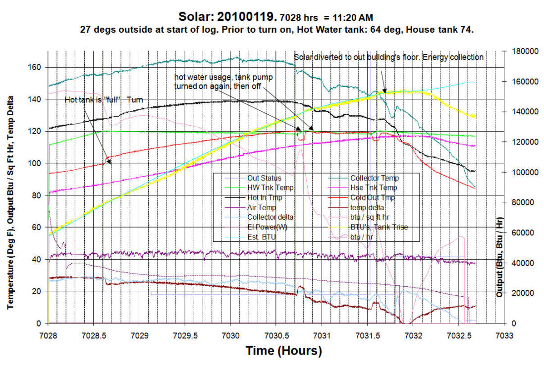
The system seems to product 1/4 to ½ of sunny output for mildly overcast days.
The log (just below) was from a 30 degree day. Measured heat collection is about
155kbtu. This is to the house and is net of any losses from the collectors to
the house.
Performance with below zero temperatures is at least 135kbtu / day. There have
been very few sunny days since the switch was turned on.
Temperature losses due to the trench seem to be mainly due to night time
cooling. Quick measurements of trench in and out temperatures do not show
measurable losses.
Click on graph for full size
Areas for improvement:
The delta between tank temperatures
and outgoing water is excessive. At 15 degrees, this is costing near 10 btu / sq
ft hr. I intend to make the flat plate heat exchanger also service the house
tank. I will make a tight coil of PEX or HDPE and drop this in the hot water
tank. The pump will then circulate the water in through rather than directly
from the tank. A second 10 watt pump will circulate water from the house tank
directly through the heat exchanger. This will drastically reduce the glycol to
collector temperature.
Additional flow through the collectors would be beneficial. Presently, a rate of
2.6 GPM is calculated based upon delta T and tank temperature rise. A high head
Grundfos UPS29-99 pump is used. The plumbing to the collectors contains many PEX
to brass T’s and such that probably have considerable flow restrictions. These
will be investigated as to the likely pressure losses. They may be replaced with
¾” copper T’s which would also remove 30’ of travel but require flow balancing
the collectors. A second pump would get the flow to about 4 GPM at a cost of 170
additional watts.
Drain back
While good intentioned, this seems more effort than it is worth. The system is
designed to allow for closed loop drain back operation. The intent was to
pneumatically pressurize the house expansion tank and depressurize the shop
expansion tank. The drain back would add 5-10kbtu / day. This is quite low on
the to do list. Time would be better spent adding insulation to the house.
To Do:
Complete and install remaining 1 + 2
x ½ collectors for the final 60 sq ft.
Update controller program.
Investigate performance enhancement.
Chad
April/May 2009, and updated January
2010
Update March 2014
The solar panels have been working quite well. The recently replaced furnace is too small for the existing solar heat exchanger. The collected heat will require diversion to either the basement or workshop floor until heat can be again directly added to the house.
The Richmond ( Paloma) electrically modulated tankless water heater failed with a code of 11 in August, just out of warranty. The error relates to gas pressure or no ignition but the flame was fine. The tankless water heater was replaced with a power vent tank water heater. Hot water temperature has since been consistent and the solar hot water tank can be run hotter without interfering with water heater operation. All household people are much happier with the new water heater. I likely would suffer bodily harm if another tankless heater was installed!
Solar System Problems:
Pipe insulation on PEX has degraded and needs replacement. Black rubber is recommended rather than inside foam.
The solar controller had a output damaged, most likely due to lightening. The controller was intended for engine control not to have 300’ of wire connected and deal with lightning pulses. It needs to have the circuits protected against excessive voltage transients.
Some crimps around the solar panels may be slowly weeping. I would recommend minimizing crimps. This is likely one of the many lessons learnt after building one system.
Glazing from Lowes has yellowed some but performance is not measurably degraded. The one panel that has had Menards 6mm twinwall glazing for 2-3 years has no visible discoloration. Additionally, Menards twinwall is less expensive that corrugated polycarbonate and easier to install. Menards SKU 1594350, $42 as of 10-20-2013.
Chad
March 13, 2014
Update November 2011:
Chad reports that the system
is running well and without any significant problems or maintenance.
Per his logging system, the
system has produced 31 million BTU, while using 570 KWH to run the
pumps.
The only problem has been that some temperature sensors mounted in PVC
hose had to be replaced because gets to them. The PVC was replaced
with copper when the sensors were replaced.