Search
The Renewable Energy site for Do-It-Yourselfers
Performance Test of Sunspace
Optimized for Solar Space Heating
|
These are the results from a test run on December 13, 2012 of our
greenhouse setup as a sunspace and optimized to provide a maximum amount
of space heating for an attached house.
The
|
|
Sunspace Setup
This sunspace is actually our new greenhouse,
which is first being setup as a sunspace to look at how well a sunspace can do
providing space heating to the house it is attached to.
The steps taken to try to optimize the configuration to provide maximum space
heating to the attached house are:
- Thermal mass in the sunspace is made as small as
possible so that solar heat is not wasted heating the sunspace mass.
- Insulation is added on the N, E, and W walls and also
on the north roof. These walls are also sealed with some care.
The insulation consists of R21 fiberglass batt insulation between the 2 by 6
studs, and then a layer of 1 inch polyiso insulation on the inside of the studs.
Total R value is about R30 with little thermal bridging.
- The floor was insulated with 1.5 inch polystyrene.
I wanted to minimize the thermal mass of the floor, so the only thing over the
polystyrene insulation now are some plywood walkways. So, its a very low
thermal mass floor.
- The fan system is intended to pull the air out of the
peak when it reaches the minimum temperature that is useful in the house for
space heating. Keeping the temperature in the sunspace down reduces
sunspace heat loss and improves efficiency.
The hope is that with these optimizations, the efficiency of the sunspace as
a collector will be in the same area as active solar air heating collectors,
while still giving you a nice place to read a book.
Insulation
The walls and ceilings were first sealed well (but no Tyvek type barrier).
Then R21 fiberglass batt insulation was installed in the stud bays and between
roof rafters. The studs and roof rafters are 2 by 6's on 24 inch centers.
I'm not a fan of fiberglass, but for this small job, it seemed the easiest way
to go. I was careful to fit the batts without gaps, and there is no wiring
or plumbing in the walls to compromise the fiberglass.
Then 1 inch Hunter rigid insulating board was installed inside the walls and
inside the roof rafters. The Hunter board is polyisocyanurate with what
appear to be light fiberglass resin reinforced face sheets on both sides.
The 1 inch rigid board adds R6.5, prevents thermal bridging through the studs,
and provides a barrier to infiltration.
Approximate R value of the walls and roof are about R27 (better than my house
:).
The overall aim of the insulation and sealing used was to make sure the
ability of the sunspace to heat an adjoining house was not compromised by
conduction losses or by infiltration.
- The 200 sqft of glazing has a UA (heat loss per degree)
of (0.5)(200) = 100 BTU/F-hr
- The 400 sqft of wall and roof has a UA of (1/27)(400) =
15 BTU/F-hr
So, the heat loss is dominated by the losses out the glazing.
The floor was first covered with a thin layer of sand, then 1.5 inch
Styrofoam insulation was placed over the sand. A couple of sheets of
plywood were added over the foam board just to give a walkway. The idea of
the foam board insulation on the floor is to prevent the direct sunlight that
falls on the floor from being conducted off into the dirt of the floor.
The idea was for this sunlight that hits the floor to be absorbed by the dark
colored weed fabric that was on the floor. The heated weed fabric then
heats the air, which rises up toward the peak for harvesting.
I'm not sure what the end floor will be, but it does seem like a bit of
a challenge for people trying to do a low mass and insulating sunspace floor to
optimize heating performance, but at the same time have something that it
practical to walk on? I decided for this test to optimize the space
heating performance.

This picture shows the R21 fiberglass batts. |
|
Vertical Screen
A vertical screen was added that starts about 18 inches directly below the
peak and hangs vertically right below the ridgeline. It extends the full
east-west dimension of the space. When the screen hits the floor, it is
carried southward on the floor to the south wall. The screen is black weed
fabric from Home Depot.
The idea of the screen was to provide surface where solar radiation could be
absorbed and converted to heat. The screen is located directly under the
peak, so heated air can rise directly up both the front and back surfaces of the
screen directly to the collection area at the peak.
The radiation that gets through the screen encounters the back (north) wall
and is absorbed there. Air heated by the back wall and roof rise up the
wall and roof slope into the collection area in the peak.
The placement of the screen could be altered to allow more flexibility in the
use of the space. The opacity of the screen might be chosen to provide a
full sun area in front of the screen and a filtered sun area behind the screen.
Fan and Controls
The fan is the same as for the bare sunspace test, and is installed in the
same location. The fan is a
Dayton 10 inch sold by Grainger
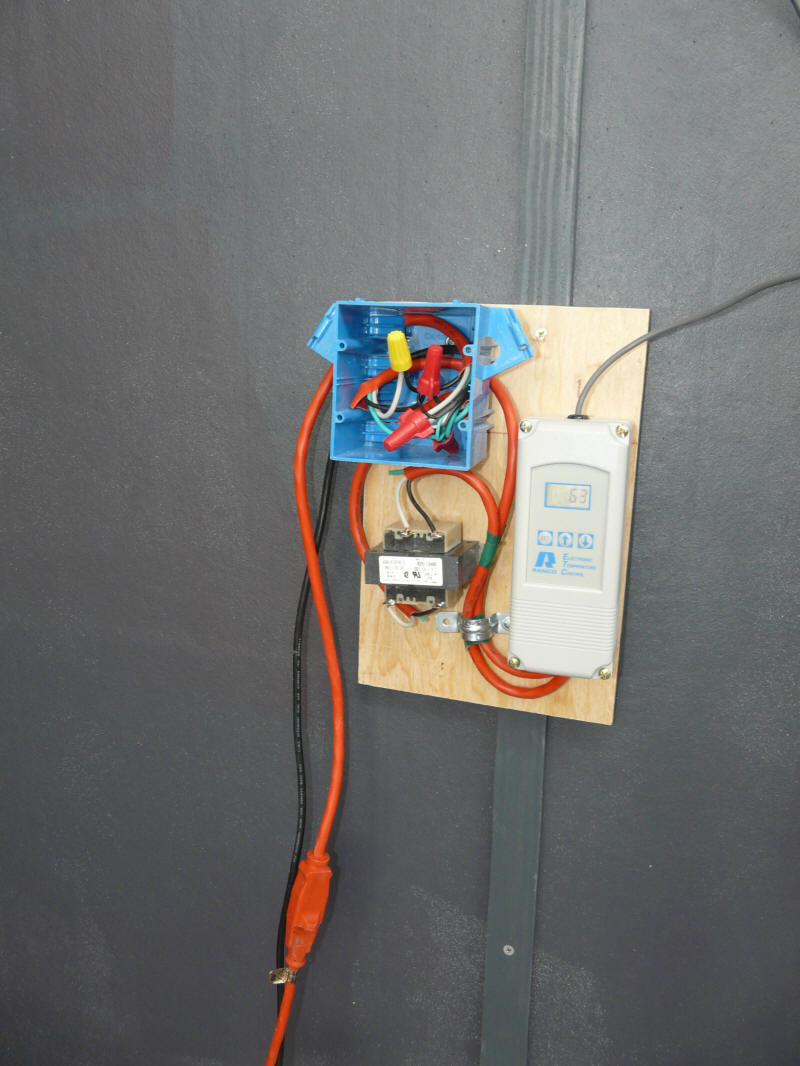
A control was added to turn the fan on when the temperature in the sunspace
peak reached a set temperature, and to turn it off when it dropped below that
temperature (with some hysteresis). The control is a Ranco Electronic
Temperature Control running its "cooling" mode (thank you Nick).

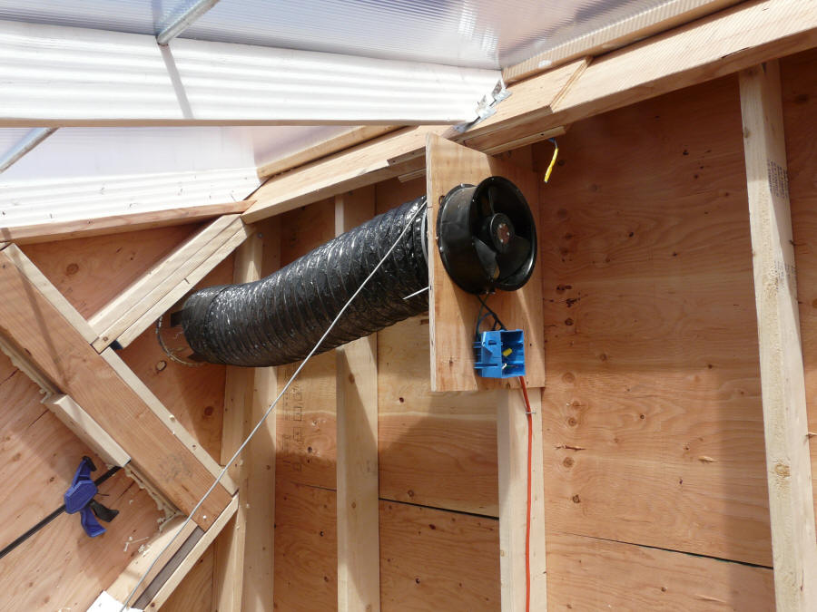
The fan in the peak of the sunspace
before the insulation was installed.
This is a nominal 600 cfm Dayton
fan 10 inches in diameter. |
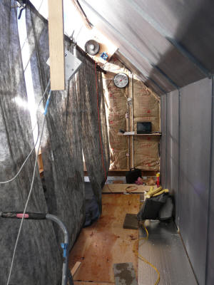
This shows the fan (up in the peak above screen)
in relationship to the sunspace. The north wall
is just to the right, and the vertical screen is just to the
left. The glazing is about 5 ft to the left of the
screen. So, idea is that air rises up
the screen and back wall as it is heated by
the hot surfaces, and makes it way to the fan
inlet, which would then be ducted to the hosue. |

The Ranco control.
The temperature sensor is mounted in the
peak area just in front of the fan. |
Sensor Locations
Performance
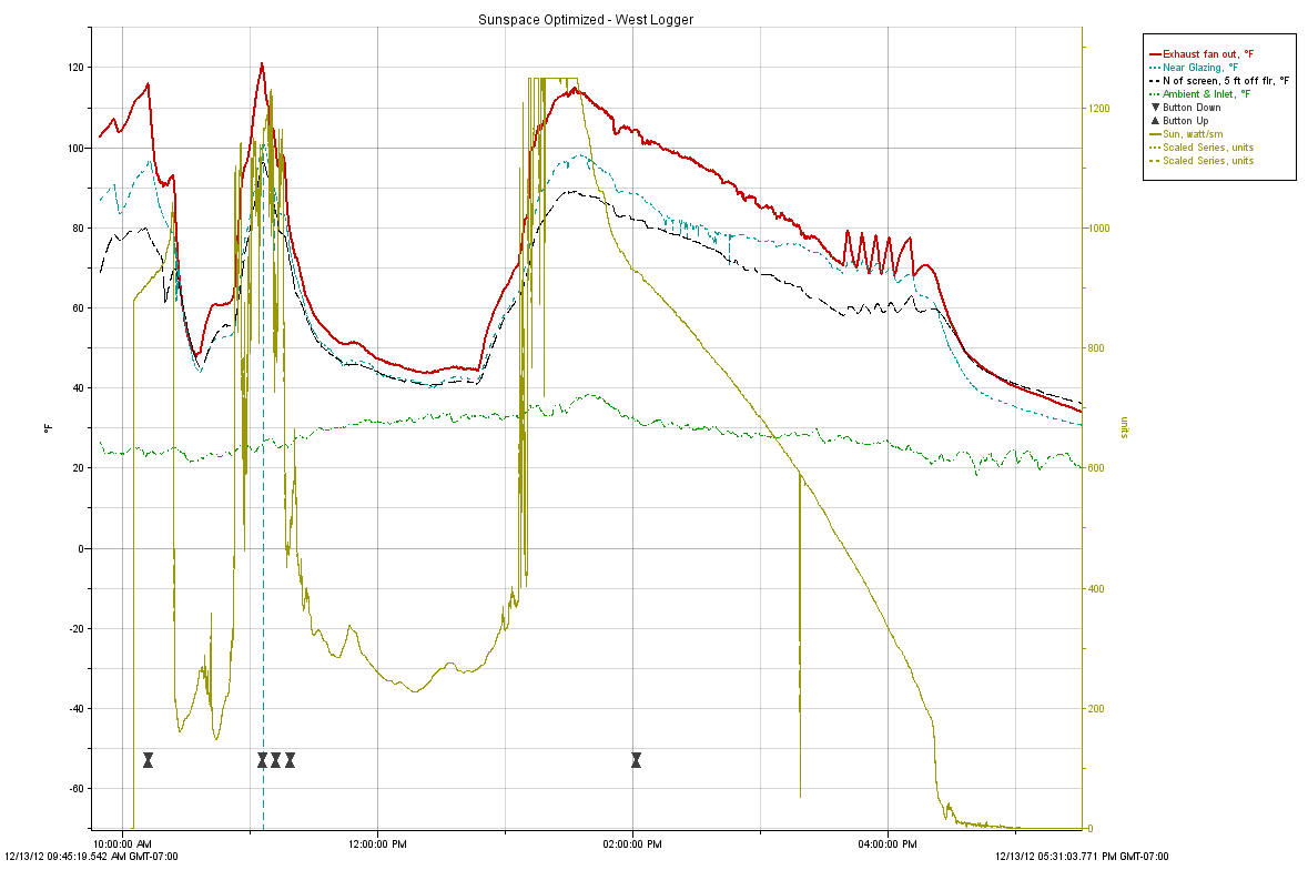
Red-solid -- Temperature of air entering the exhaust fan
-- near peak on west end.
Yellow/Green-Solid -- Sun in watt/sm measured in the
plane of the glazing and with strong snow reflection
Aqua-shortdash -- Temperature measured just behind
glazing with tape shading sensor. About 6 ft above floor.
Black-long dash -- North of screen, 55 inches off floor,
midway between screen and north wall.
The temperature measured near the glazing seems high (only about 15F cooler
than the temp at fan inlet). This increases losses through the glazing.
For example, when the temperature just behind the glazing at about 6 ft up is
near 100F, the temperature a foot off the floor in the inlet flow is more like
30F. Maybe the inlet air should be introduced high up on the glazing and
(somehow) constrained to wash down the glazing to keep it cooler?
The sun intensity reaches the pyranometers limit of 1250 w/sm for a few
minutes at about 1:15 pm. This may seem surprising, as full sun is often
listed as 1000 w/sm. The reasons for the high value are: 1) strong
reflection from fresh snow to south, 2) possibly some reflections from clouds
that were off to side, 3) our high altitude and clear skies. When I
first got the pyranometer and saw this a couple years ago, I sent the
pyranometer back in for calibration thinking it had to be wrong, but it
calibrated right on, and the makers of the pyranometer tell me these kinds of
high readings happen at their location in Utah as well.
The day was fairly sunny with clouds coming through. There do not
appear to be any times in which the conditions are steady enough to do an
efficiency estimate -- have to leave that for a more sunny day.
Temperatures in various parts of the insulated sunspace.
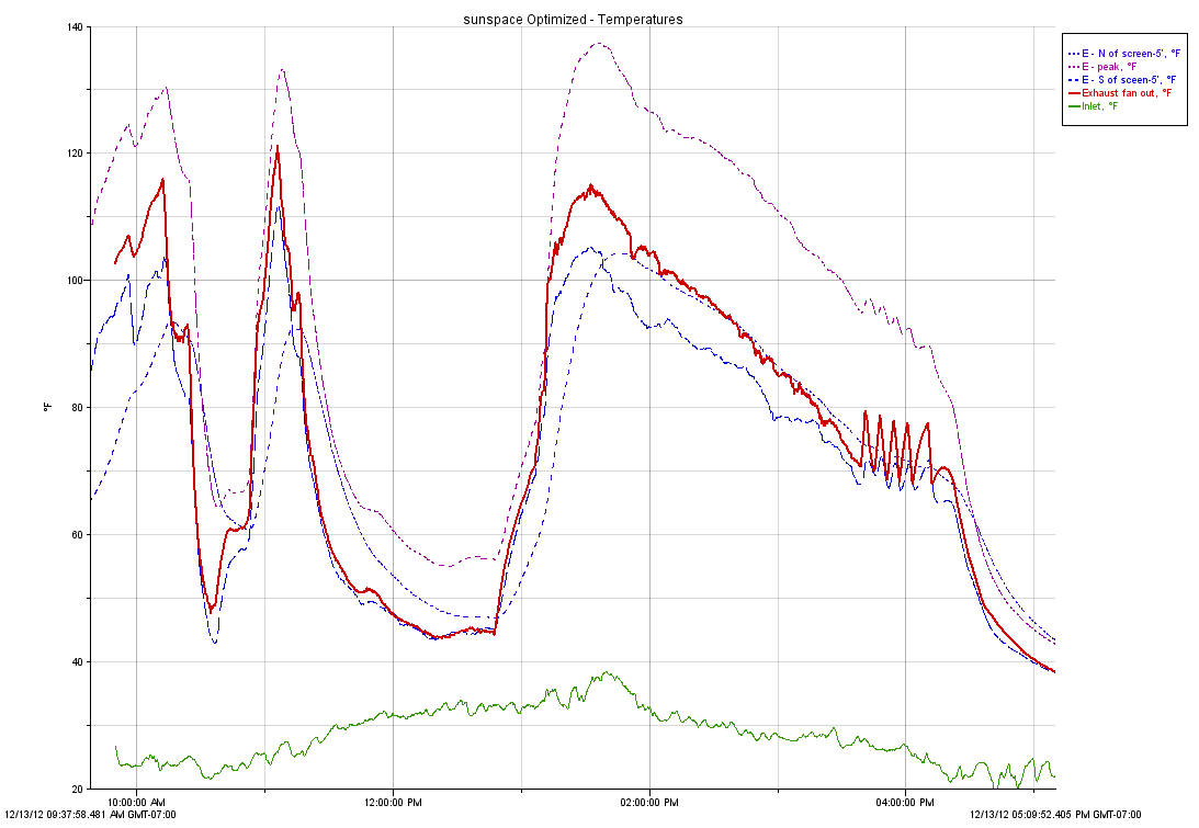
Purple -- East end, near peak -- 4 ft from east end, 12
inches down from peak.
Blue-shortdash - East end, North of screen --
4 ft from east end, 55 inches off floor, North of screen and midway between
screen and north wall.
Blue-longdash -- East end, South of screen -- 4 ft from
east end, 55 inches off floor, South of screen and midway between screen and
glazing.
Green-solid -- Ambient and inlet temperatures.
Red solid -- Temperature of air entering the exhaust fan
-- near peak on west end.
The big dips in temperature are, of course, when the sun was behind clouds.
The temperature at the peak on the east end runs about 20F hotter than the
west end peak at the exhaust fan, so, a better job could be done getting the hot
air uniformly out of the peak.
The nearly 140F peak temperature seems wasteful -- especially when the inlet
temperature is in the 30'sF.
Temperatures in front of and behind the dark screen are pretty close to each
other with the north one lagging the south one by a few minutes.
Air Velocities
I was able to get some air velocity measurements around the sunspace during
the full sun conditions:
Immediately behind screen -- Upward velocities of about
60 fpm over most of screen -- smoke pencil also showed upward flow.
Immediately in front of screen -- Upward air velocity
that was just a bit slower than behind the screen.
Back wall -- Upward velocity -- stronger as you went up
from floor -- about 60 to 65 fpm
Inlet areas -- Strong flow into inlets and down near the
floor heading along the south wall toward the center, but also somewhat to the
north. The inlet flow visibly moved the weed fabric. Flow velocity
in the 100 to 200 fpm starting at each inlet, and staying strong nearly to the
center.
IR Pictures
Controls
Toward the end of this day, I hooked up a thermostatic control for to turn
the fan on automatically when the sunspace peak temperature reached a set
temperature, and turn it of when it drops (with some hysteresis). I
used a Ranco controller with its temperature sensor mounted near the fan inlet.
This is not a very fancy control system, but appears to be working fairly well.
I think that a multi speed fan or a variable speed fan would be better.
It could provide high flow rates for full sun conditions and lower flow rates
for part sun or very cold conditions. So, the air delivered to the house
is about the same temperature and the sunspace temperature is better controlled
as well.