Search
The Renewable Energy site for Do-It-Yourselfers
Thermal Performance Test -- Low
Thermal Mass Sunspace for Space Heating -- Non-Optimized
|
This page describes a sunny day test of a low
thermal mass sunspace setup to produce space heating for the house
its attached to.
This is one of a three part test to measure how well sunspaces do as
space heaters for homes. Test 1
and Test 2 are tests of the sunspace
after it has been optimized for solar space heating. This test was
done earlier before the sunspace was optimized for efficient space
heating. It gives an idea how worthwhile it is to spend money on
the optimizations (which are detailed below).
 I would
suggest reading the results from Test 1
(the optimized sunspace) before going through this one.
Back to the sunspace main page... |
|
Page Index
Configuration for Non-Optimized Test
Ideally, an attached sunspace that is used primarily to provide
solar heat to the attached house would have these features:
- Large area of south facing glazing at a steep tilt angle for good solar
heat collection -- double glazed in colder climates.
- Low thermal mass so that the solar heat is sent to the house rather than
warming sunspace thermal mass.
- Insulated east, west, and north walls and insulation on any non-glazed
ceiling areas to reduce heat loss to the outdoors.
- An insulated floor so that the floor does not absorb solar energy.
- A heat distribution system (fan and ducting) that removes hot air from
the sunspace as quickly as it is made and returns cool room air to the
sunspace.
- All dark surfaces that absorb heat well.
The idea of all these features is to harvest as much of the sunspace heat as
possible for use in the house rather than having it go into heating the
sunspace.
So, this sunspace has these good features:
- Large, steeply tilted south facing glazing.
- A fan to carry heat away efficiently.
It has these bad features:
- Does not have absorbing surfaces painted dark (so some solar gets
reflected)
- Does not have insulation on the non-glazed walls and ceilings (so more
heat loss for these surfaces)
- Has a bare dirt floor, which absorbs solar heat (so heat absorbed by
floor does not get delivered to the house)
A latter test will look at the performance after adding wall and ceiling
insulation and floor insulation to see how much difference it makes.
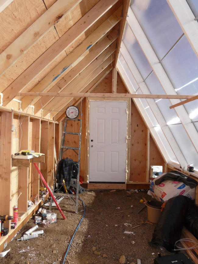
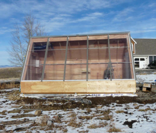
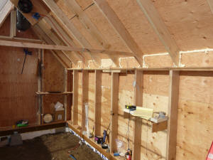
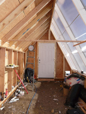
Some pictures of the sunspace/greenhouse as it was for the test:
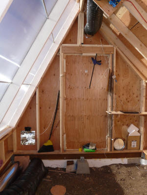
Looking west inside the sunspace. |

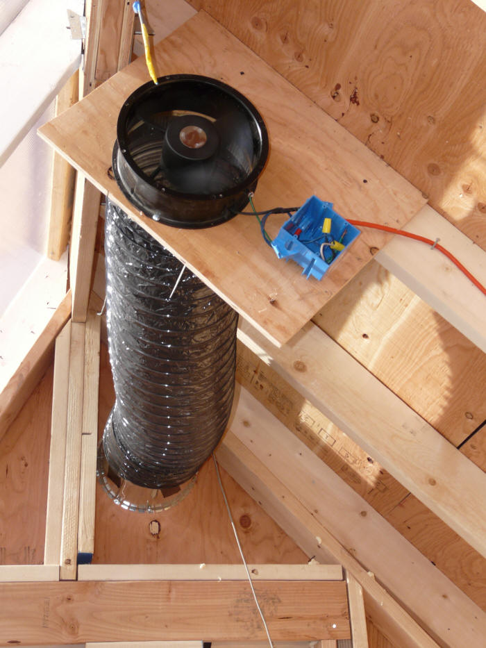
sunspace exhaust fan near peak |
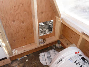
Inlet vent is currently just two 1 ft square
openings to the outside
on the east and west walls. |
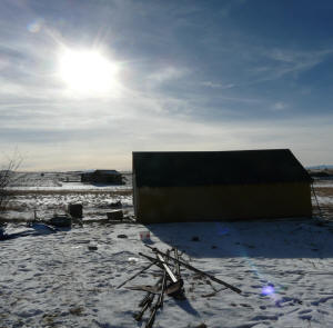
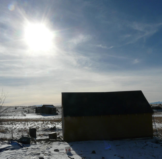
Sun conditions for the test. |
pretty well sealed, but no insulation. |
Looking east. |
Space Heating Performance
This is the performance plot for November 28, 2012 with the
greenhouse/sunspace in the configuration shown above (non-optimized).
Temperatures at the inlet, outlet and at several points in the structure were
logged along with solar intensity.
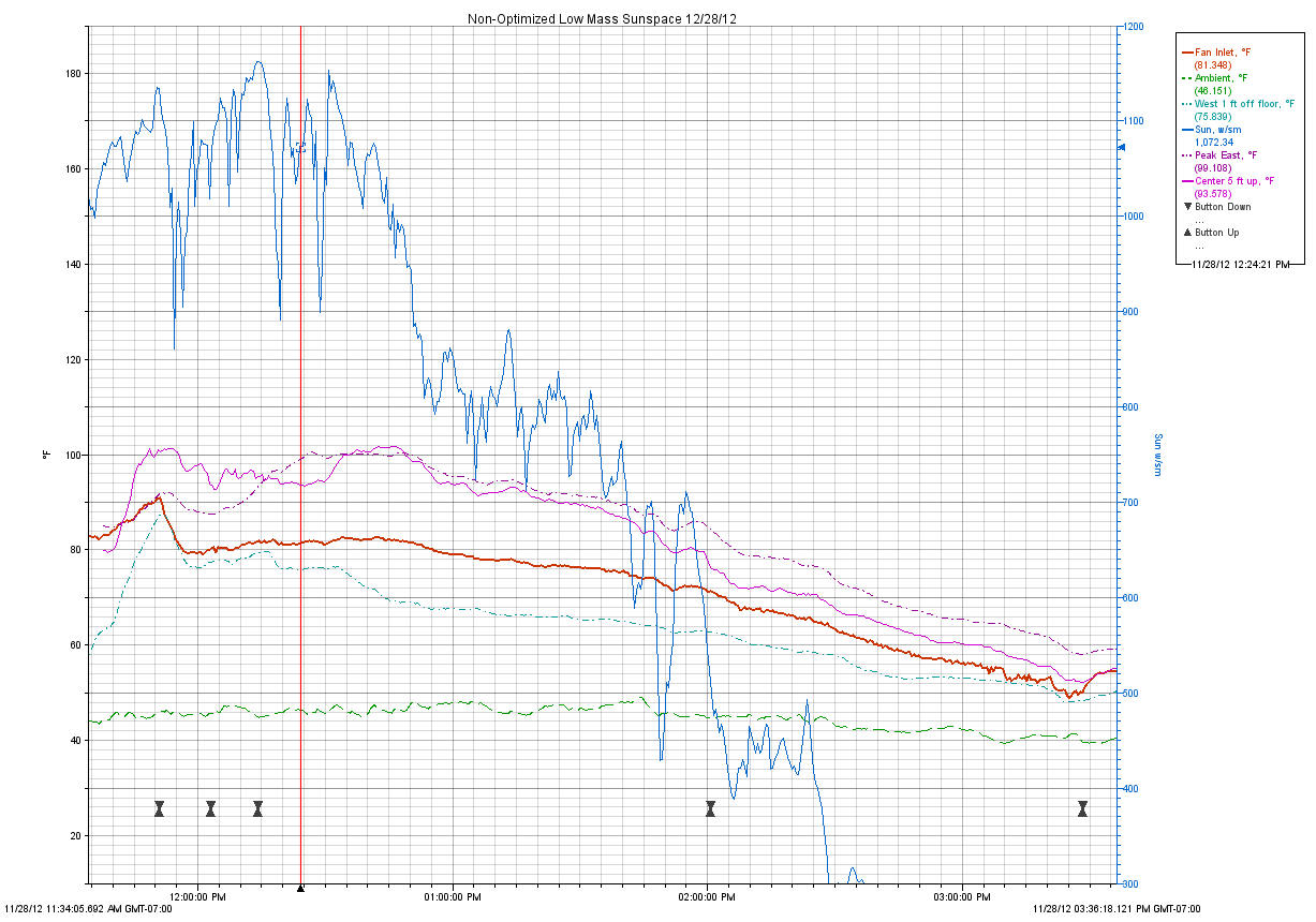
Red Solid -- Space heating outlet temperature (F)
(exhaust fan inlet temperature)
Green Dash -- Ambient temperature (F) (measured
outside the north wall)
Aqua Dash-Dot -- Temperature 1 ft above floor near
west end (F)
Blue solid line -- Solar radiation on glazing surface
(watts/sm)
Purple Dash-Dot -- Temperature at peak near east end (F)
Purple Solid -- Temperature near center of space at 6 ft
above floor (F)
The sun around noon was good at about 1100 w/sm -- this is measured in the
plane of the glazing and includes snow reflection. There was a faint but
visible cloud layer in front of the sun much of the day. By about 1pm the
clouds had increased and the sun level dropped to about 750 w/sm. The sun
measurements were taken with an Apogee pyranometer mounted in the glazing plane.
Its interesting to the note that the fan inlet temperatures averaged 15 to
20F lower than the peak temperature and also lower than the temperature at 5 ft
off the floor. So, perhaps a better way is needed to pull the hot air out
of the peak across the full width? Not sure where the cooler air that is
finding its way to the fan inlet is coming from?
During the highest sun periods, the sunspace heated the air from about 43F up
to 83F, or about a 40F warm-up -- probably about the right amount of heating.
If the inlet air had been 60F room air, then the exit air would have been closer
to 100F, which seems about right.
Later in the day, when the sun dropped to about 700 w/sm, the air was warmed
from about 46 F up to about 76F, or about 30F. This is when a
variable speed fan that could drop the flow rate a bit to allow for more
temperature rise might be nice.
Velocity and Flow
The exit vent velocity was measured several times during the test and ranged
from 630fpm in the early part of the testing (noon) up to about 685 fpm at 2 pm.
The flow is measured in a 10 inch duct with an area of 0.55 sf. This gives
an exit flow rate of about 350 cfm to 375 cfm.
The velocities at the inlets were also measured at around 200 fpm. Each
inlet is 1 sf, so the flow rate calculated using the center of inlet velocities
would be 400 cfm -- more than the exit flow. I attribute this to a fall
off toward the edges of the square inlet openings.
The flow rate is about 350 cfm and the volume of the space is about 1400 cf,
so it takes about 4 minutes to introduce enough new air through the inlets to
fill the space.
The flow rate per sqft of glazing is about 350/200 = 1.8 cfm per sqft.
This is a bit lower than what is typically used for good performance in an
active collector.
| |
Update Jan 12, 2013
On the later two tests in January there were some changes to the
velocity measurement and fan setup: 1) a 2nd fan was added to
accommodate more heat production from the optimized sunspaces, and to
provide two pick up points in the peak, and 2) the velocity measurements
were refined by extending the ducts and adding flow separators.
So, I have a little less confidence in the duct velocity measurements
and flow rate for this test than the later ones. That said, it the
readings do seem about right compared with the later tests.
Gary |
Floor and Wall Temperatures
I checked the dirt floor temperatures several times both in the sunlit areas
and the shaded areas. The results were a bit surprising.
The sunlit floor near the north wall started at about 97F just as the fan was
turned on to start the test, and dropped to mid 70's as the test was going.
It reached about 60F by the end of the test. So, it appears that there
even though there was good sunshine directly on the dirt floor, there was enough
airflow over the dirt to drop the temperature of the floor during the test.
The shaded floor just north of the low south wall was about 59F at the start
of the test, and dropped down to the 36 to 40F range. I believe that this
was the influence of the cold air streams coming into the inlet vents located
low in the east and west walls near the south wall. That is, the cold vent
air flows tracked low along the south wall cooling the floor.
All of the floor temperatures were just surface temperatures -- I did not see
what was happening a ways down into the dirt.
The back wall temperature behaved similarly, stating at around 99F and
dropping down to 60 to 75F during the test. Again, the airflow
appeared to cool the back wall once the fan was going.
Living in Your Collector
Since one good reason to build a sunspace is to have a nice place to spend
some time, I'll pass on some experiences from spending time in mine.
Without the fan running, the space can be quite hot -- up to 120F and more.
Not a space you would like to spend much time. But, a good space for doing
laundry or installing a solar water heater.
With the fan removing heat the sunspace can be quite comfortable. The
temperatures drop down into the nice range, its brightly lighted, there is just
a bit of air current, which feels good. It would be a great place to
have a cup of coffee and read the paper -- something you can't say about the
inside of most solar collectors.
The fan I am using is a
Dayton 10 inch 600 cfm fan from Grainger. Its pretty quiet, but
still too noisy to live with if its mounted right in the sunspace.
It might do better with some kind of isolated mount. I think that choosing
a quiet fan that produces the right amount of airflow is something that deserves
a lot of attention in sunspace design.
Contrast to Active Collector
In this application, the sunspace is being used as an alternative to a
conventional solar air heating collector to provide space heating.
Its interesting to note some of the contrasts.
- The flow velocities are much lower in the sunspace -- in most places I
can't measure them with a good air velocity meter and you really can't feel
them, but in a conventional collector, air velocities are fairly high -- up
toward 100 fpm.
- In a conventional collector, there is usually a significant air velocity
along the glazing, where as in the sunspace its too small to measure.
- The surfaces that absorb the solar radiation are spaced further from the
glazing, are larger, and run cooler.
- The flow pattern in a conventional collector can (it seems) be
controlled more precisely with channels, baffles, screens, ... than for a
sunspace.
- The sunspace has more outer heat loss area and more potential leakage
area.
Items 1 through 3 would seem to me to favor the sunspace as an efficient heat
collector with low losses?
Items 4 and 5 would seem to favor the conventional collector?
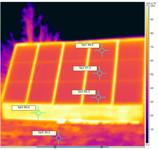
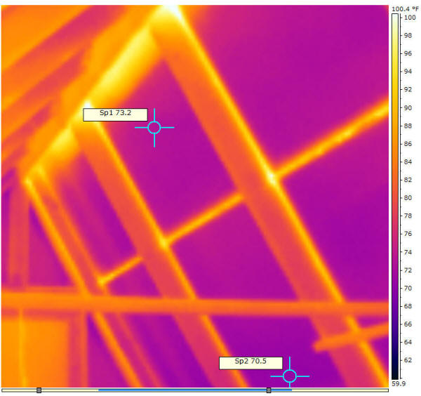
IR Pictures
Thermal camera pictures of the glazing from outside and inside during the
test at around noon.
At the time these images were taken, temperatures were: Peak of sunspace 95F, at 6 ft near center 95F, ambient 45F, Inlet air 45F.
Smoke Test
A smoke test was done to have a look at airflow patterns. The 90 second
smoke pellet was placed in the East inlet vent with the fan operating.
The inlet where the smoke pellet was ignited is low in the east wall near the
south glazing (pictures above). The smoke rushed into the inlet and
proceeded west staying low and moving quickly. As it approached the middle
of the front wall of the GH, it encountered the stream of inlet air from the
west vent and this caused it to spread out and slowly move upward -- it did not
penetrate the air stream from the west inlet at all. Over some time
(3 minutes?) the smoke spread out horizontally and then upward in what seemed
like a fairly slow and diffuse way. It basically filled the whole GH
with a diffuse smoke that gradually made its way up to the peak and then out the
fan.
The flow rate is about 350 cfm and the volume of the space is about 1400 cf,
so it takes about 4 minutes to introduce enough new air through the inlets to
fill the space.
Velocity Survey
I walked the GH with a hot wire anemometer trying to get an idea where the
air currents were flowing. Basically the air currents in nearly all of the
GH were too low (less than 2 fpm) to measure with the anemometer. The
exceptions were within about 4 ft of the inlets and the exit fan.
So, any flow channels or paths that exist are too low in velocity to detect with
the hot wire anemometer.
Performance
Some rough estimates of heat output and even rougher estimates of efficiency.
Looking at 12:30 pm
Solar input = (1050 w/sm)(200 sf)(1 sm/10.76sf) (3.412
BTU/h / watt) = 66590 BTU/hr
Heat output = (367 cf/min)(0.061lb/cf)(81.6F - 45.4F)(60
min/hr)(0.24 BTU/lb-F) = 11680 BTU/hr
An implied rough effic of = (11680 BTU/h)/(66590 BTU/h) =
17.5%
At 1:30 pm
Solar input = (770 w/sm)(200 sf)(1 sm/10.76sf) (3.412
BTU/h / watt) = 48830 BTU/hr
Heat output = (367 cf/min)(0.061lb/cf)(76.3F - 46.4F)(60
min/hr)(0.24 BTU/lb-F) = 9640 BTU/hr
An implied rough effic of = (9640 BTU/h)/(48830 BTU/h) =
19.7
So, around 20% efficiency is not is not exactly stellar, but 12,000 BTU/hr
from a modest sized sunspace is definitely a useful amount of space heating.
Just for comparison, its about equivalent to a 4000 watt PV array at the STC
rating.
I expect that once the sunspace is optimized for heating in the next test it
will do better.
In the
screen absorber collector testing that Scott and I did last year, the sunny
winter day efficiencies were in the 40% ballpark.
Next Test
For the next test, I will insulate the floor and also insulate all wall and
the north ceiling. I'll repeat the same sort of test and see how
much difference it makes.
I am inclined to think that the difference will be significant.
The sun shining directly on the dirt floor as it does now should result in a
significant fraction being absorbed directly by the ground and not getting to
the "house". For the insulation, the total area to be insulated is about
300 sf. If you assume that the average inside temperature is 70F and
outside is 30F, and that the current plywood walls are R1, then the heat loss is
(300sf)(70F - 30F)/(R1) = 12,000 BTU/hr. The total solar incident on
the 200 sf of glazing is about 60000 BTU/hr, and you would expect to only
harvest about half of that in a good collector, so the 12K BTU/hr is a
worthwhile fraction of that.
I guess we will see.
If you have any ideas or suggestions, please leave a
comment on this page....
November 28, 2012
Gary