The collector loop plumbing for drain back systems normally has to
slope downward toward toward the storage tank for the full length of
both the supply and return pipes. The penalty for getting careless
on this is often a system that does not drain, and collectors with
freeze damage -- not fun.
This is a note from Kevin Dickson on a way to handle drain back
plumbing that does not slope down toward the tank all the way, but
instead has a rise in it at some point. If this suggestion did not
come from Kevin, who has decades of experience in solar thermal, I would
not pass it on at all. But, coming from Kevin, I have to believe
that it works. I would still be very very careful
in applying this technique, and be sure to test that the system is
draining fully when you finish.
Handling Drain Back Plumbing with Dips -- From Kevin:
Gary,
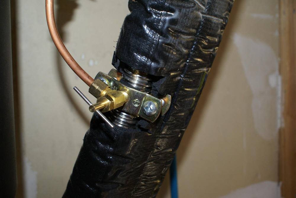
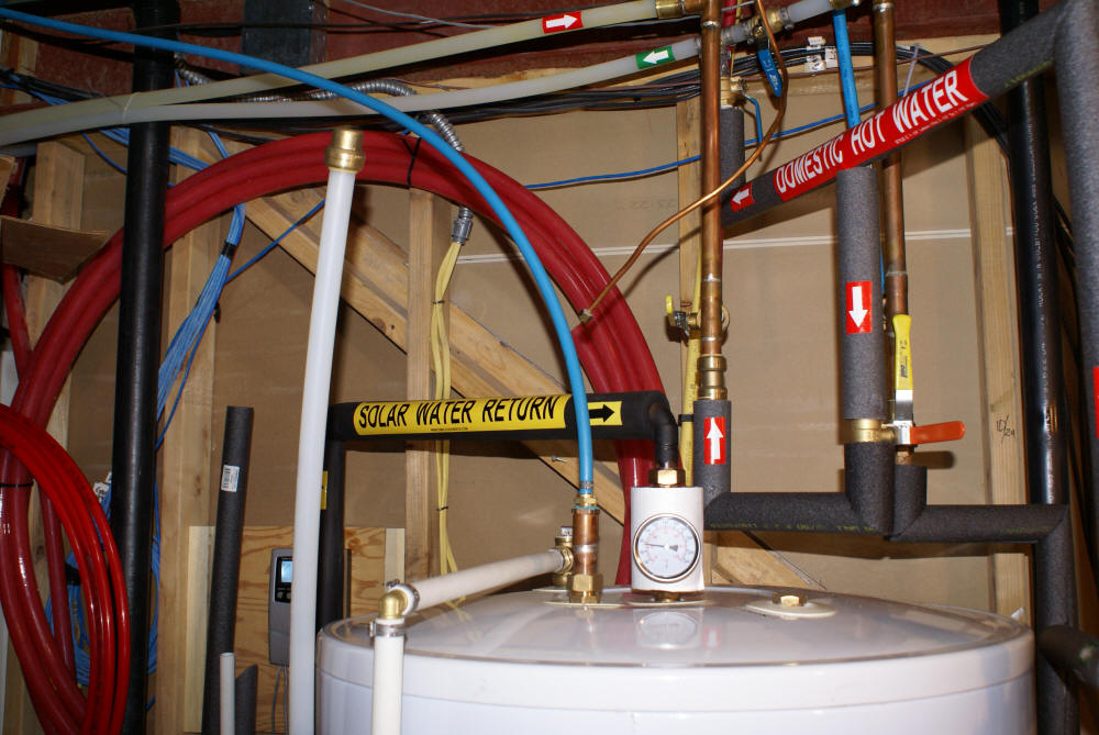
Here are photos of the "air relief line" for problem drainback
installations.
In this case the homeowner had run
solarflex down into the basement floor
then up thru the garage. So the tank water level is five feet higher than
the lowest spot in the piping.
We used a saddle valve because solar flex fittings are not "on the
shelf". The small opening of the saddle valve is no problem because a 1/8"
hole for the air relief is sufficient.
The design and installation criteria haven't been "lab verified", but you
can always get the water to fall out of the upper piping with this trick.
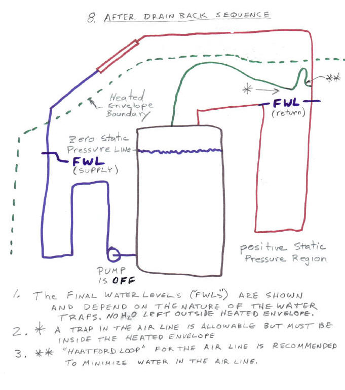
The air line shouldn't have any big traps. If it is perfectly sloped,
then both the collector supply and return lines will drain completely down
to the water level in the tank. A little water may remain in any traps
where they occur. So the traps must be inside the heated envelope.
Now, if you can have a perfectly sloped air line, you usually don't need
this trick because you could probably run untrapped supply and return lines
also. So it's a given that your air line may have traps. However, when
the pump stops, any water in the air line should be sucked into the
collector return line. On drainback systems, there is always suction on
the return line. A drainback collector loop behaves as a siphon on the
return side from the top down.
To minimize water from getting into the air line, I run the vent line up
first, then down and back to the tank top (see the blue pipe in the photos).
This "solar Hartford loop" should prevent any water from getting into the
vent line. The air line should be at least two pipe sizes smaller than the
solar loop and 1/4" minimum. 3/8" is fine for most systems. 1/2" is only
OK on really big systems, and there's no need to exceed 1/2"
Why am I so worried about water in the air line? Well, if there's a lot
of it, it tends to pull water up higher than the tank level after drainback
stops. The volume of the water in the collector loop wants to drain out
because of gravity. But it can't unless an equal amount of air can get in
to replace it.
I really need a You Tube video with clear pipe to show the dynamics.
(you tube of U-tubes?)
Note: in atmospheric tanks like yours, Gary, the air vent line can just
be a 3ft. standpipe. Until siphonic flow is established in the collector
loop, water will gurgle out into the standpipe. When siphon is established,
that water flows back into the return line.
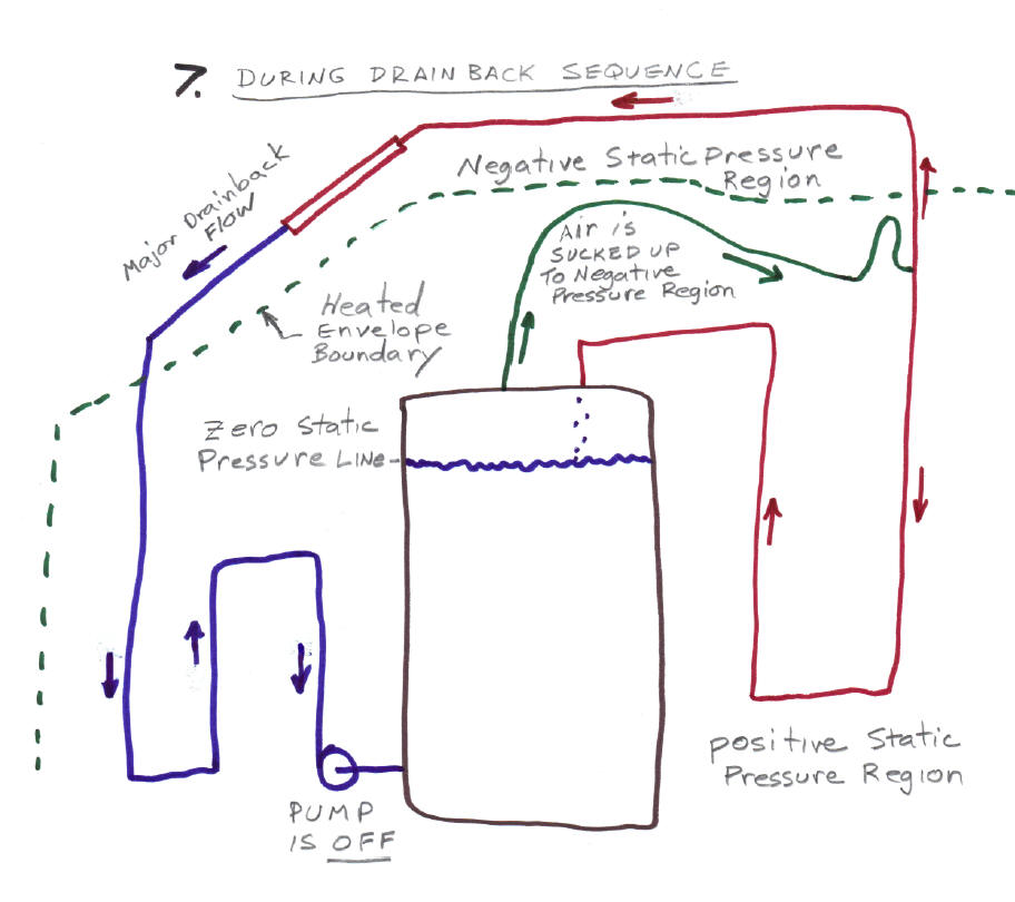
Kevin provided the following diagrams to show why this scheme works:
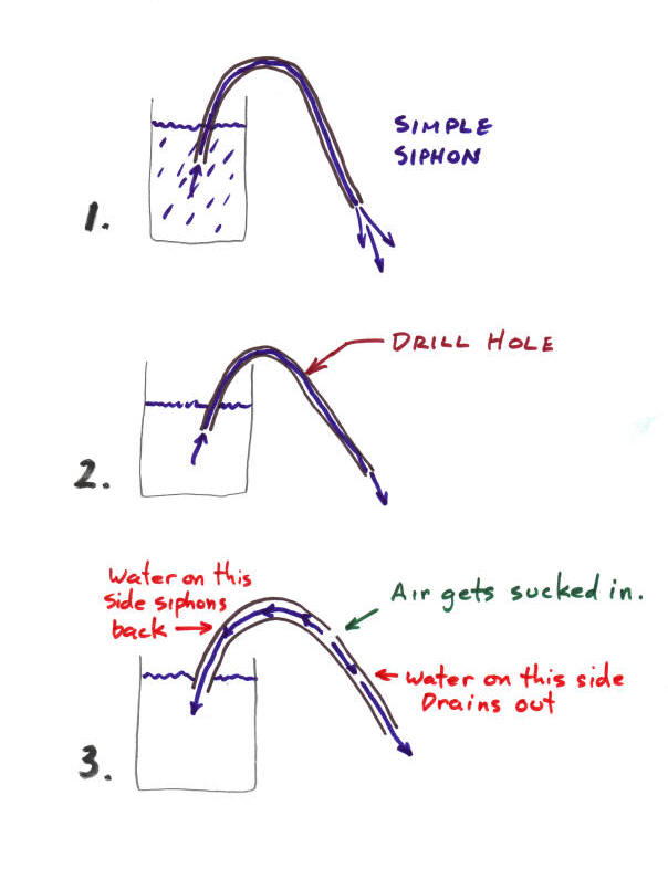
Drawings 1,2, 3: If you introduce an air leak into an operating siphon,
the siphon action stops and the water drains in both directions from the
point of the air leak.
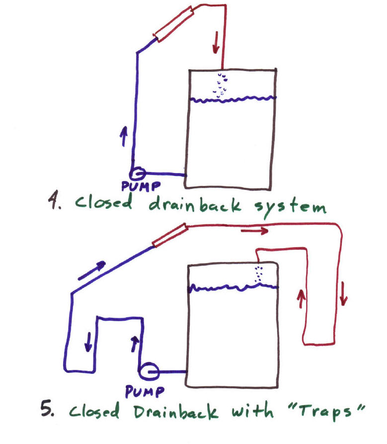
Drawing 4 shows a closed drain back system. A closed drain back
system is not vented to the outside. This is in contrast to a
lot of the drain backs shown on Build-It-Solar that have the tank vented to
outside air. In this system, when the pump stops, air
begins to flow up the return line from the tank -- if this air can't flow up
the return line to replace the draining water, then the water won't drain.
Drawing 5 is the same type of closed drain back system, but with a dip
(trap) in the plumbing. If nothing further is done, this
system will not drain back because the trap will prevent air from
flowing up the return line. This system provides no freeze protection.
Drawing 6 shows the closed loop drain back with an air relief line added.
The relief line allows air to flow from the tank to to a point beyond the
trap, and with this air to replace the water, the system will drain back.
To summarize:
1. Drainback systems can have water traps inside the heated envelope
if an "air relief" is installed.
2. The air relief line is a 1/4" or 3/8" line from the top of the
tank above water level to anywhere on the return line above the tank
water level.
3. Any traps in the air relief line must be inside the heated
envelope.