Search
The Renewable Energy site for Do-It-Yourselfers
Construction of a Solar Water
Heating Collector Using PEX Pipe
|
The pictures below detail the
construction used on the prototype collector.
I've provided quite a bit of detail
on the construction of the prototype for two reasons: 1) I like the way it
went together, and I think its not a bad design for collectors in general, and
2) I'm looking for ways to improve the design and make it even easier to build
(from you).
As always, comments are welcome
Gary...
|
|
Construction Overview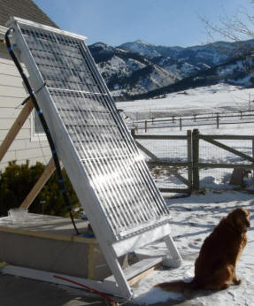
This is how it goes together:
-
PEX-AL-PEX pipe is laid down in a
serpentine pattern on plywood sheet that backs up the absorber.
-
The absorber is made from 6 inch
wide aluminum strips with grooves that snuggly fit over the PEX pipe.
-
The absorber is fit into a frame
made from 2 by lumber.
-
An insulation panel is fitted
behind the absorber.
-
The SunTuf corrugated
polycarbonate glazing is installed.
This is nothing fancy, and is easy to
build with ordinary tools and skills, and it looks pretty good (at least to me
:). Most people will find all the materials are available locally.
Building the Absorber
The absorber uses a sheet of 4X8
plywood as a backing and a surface to staple the aluminum absorber fins to.
You may need to trim the plywood sheet to insure that after it is fitted into
the frame, the glazing will fit properly. To determine the size of the
plywood absorber backing board: start from the glazing size, then figure out the
frame size to support the glazing, then figure out the size of the absorber.
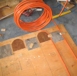
Step 1: Lay out the line you
want the PEX tubing to take down the absorber.
A single length of PEX
tubing can be used for the entire run -- there is no need for fittings of any
kind inside the collector.
I used a serpentine pattern with a little bit
of drop in elevation on each of the serpentine straight segments (to encourage
draining).
While the manufacturer states that the
minimum bend diameter is about 6.4 inches, I have found that its possible to go
down to do a 5 inch diameter bend with no additional difficulty, and no apparent
ill effects.
I would recommend using fins with a finished width of about 6 inches.
Wider fins work less efficiently, and they require more heat transfer into the PEX pipe per foot of length than narrower fins.
Be sure that the fins will extend all
the way to the next fin -- don't leave any gaps between adjacent fins. On
the prototype, I miscalculated and left about half inch gaps -- this just wastes
absorber area.
| Click on the pictures
to see full size view |
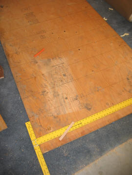
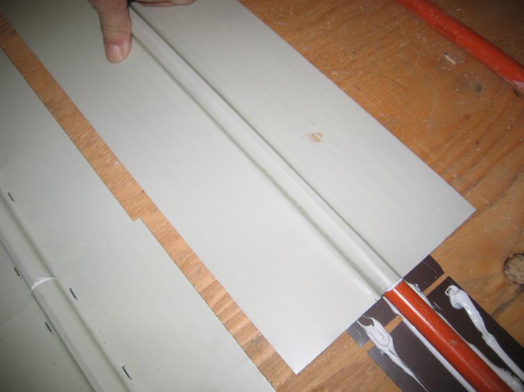
Laying out the PEX tube pattern
on the plywood. |
Laying out the lines that
the PEX will follow. |
After you work this out, layout the
pattern on the plywood with a marker.
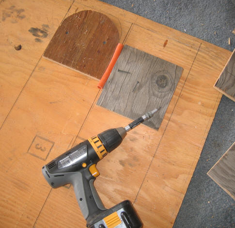
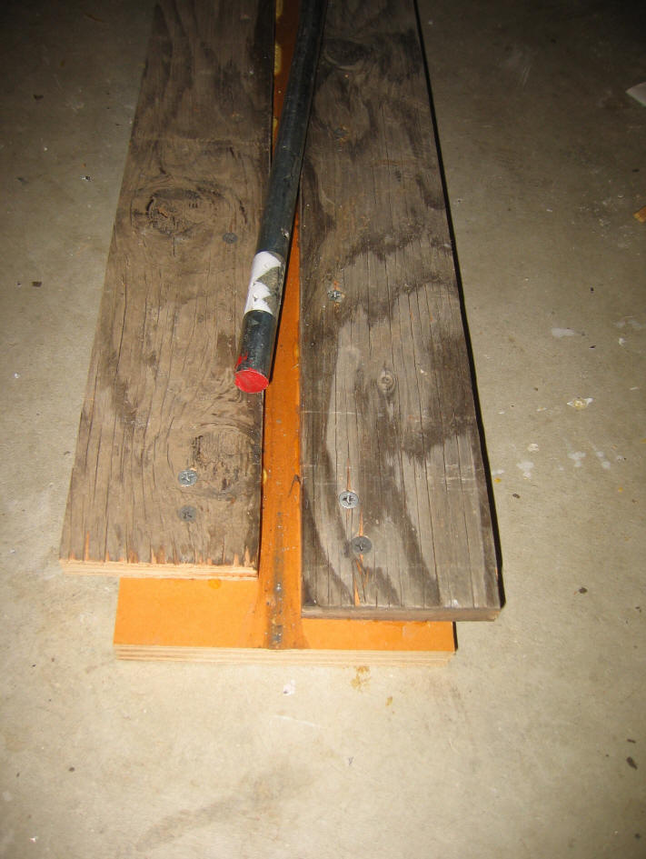
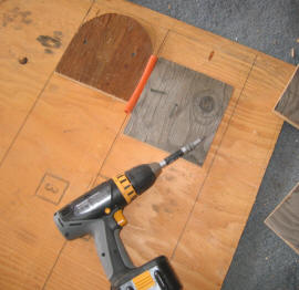
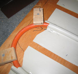
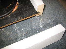
Step 2: Make some simple forms
from scrap plywood (see picture) that you can screw to the plywood to bend the PEX around. These are very fast to make -- I made enough to do about half
the collector. After the pipe was bent around the forms for the first half
of the collector, I removed the bending forms and used them for the 2nd half.
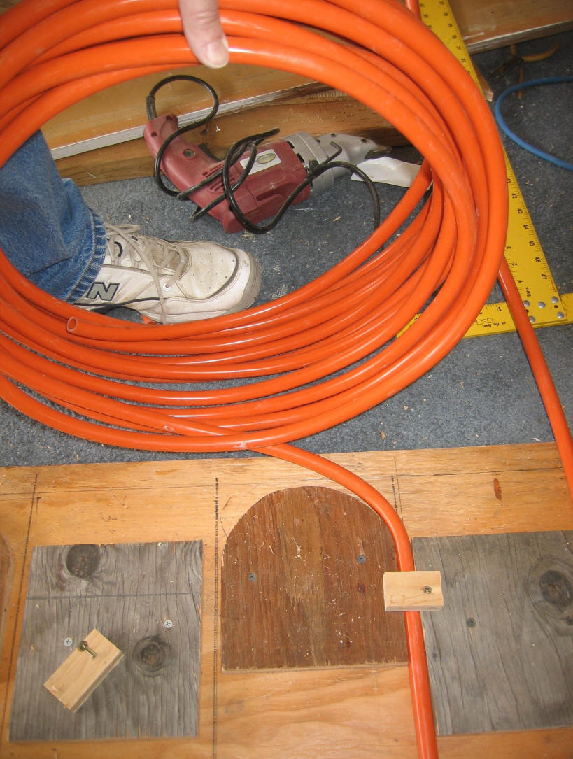
Screw the forms to the plywood, and
route the PEX around the forms. Some screw down plywood clips made from
scrap will
help to keep the PEX from moving once its in the shape you want.
Keeping
the plane of the coil vertical as you bend the PEX around each form avoids any
tendency to develop twists (see picture). This is where using
PEX-AL-PEX instead of PEX makes the job a lot easier -- the PEX-AL-PEX holds its
shape after you bend it with little tendency to spring back.
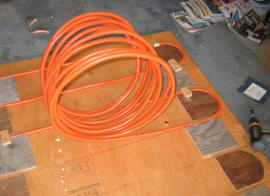
Forms to bend the PEX around. |
Bending the PEX around the forms.
Little plywood screw down clips
hold the PEX in place.
|

Keep the plane of the coil
vertical as you go around the bend. |
Step 3: Apply the aluminum fins
over the PEX-AL-PEX. Its really important to the efficiency of the
collector to get a snug fit between the fins and the PEX.
Here is the sequence I used on each
serpentine run:
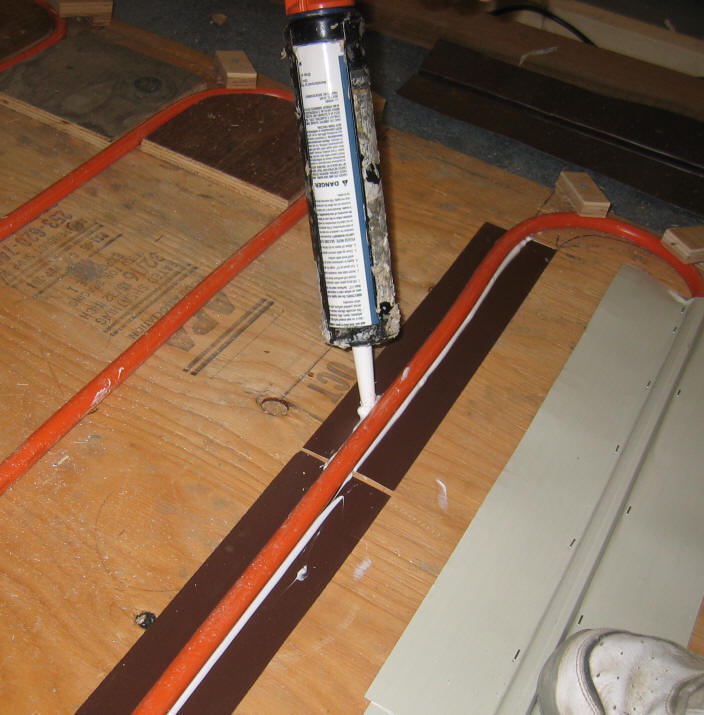
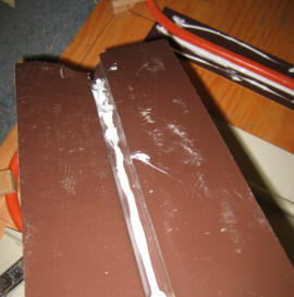
-
Place a strip of flat aluminum
fin material under the PEX.
-
Put a bead of silicone along the
tube on each side between the tube and the flat aluminum strip.
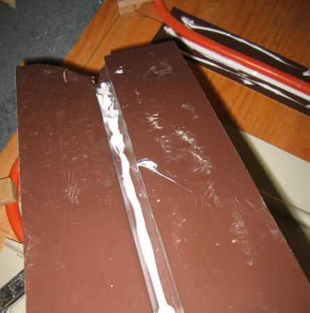
Trim the ends of the grooved
aluminum fin as shown in the picture so that the fin extends as far into the
bend at each end as possible. Make sure there are no sharp edges that
could damage the PEX.
-
Place a bead of silicone in the
groove of the fin and press it firmly down onto the PEX. Check to make
sure the gap between the PEX and the aluminum is very small and is filled
with silicone -- the gap should be paper thin.

Place a strip of aluminum under
the PEX, and silicone caulk
along each side. |
Trim the ends of the fins so
that they go a ways into the
PEX bend. The more aluminum absorber surface the better. |
Put a bead of silicone in the
groove of the fin before
placing it on to the PEX. |
-
Staple the fin to the underlying
plywood while pressing the fin tightly against the PEX. About every 5
inches.
-
Put a few staples in each fin
about half way out from the center to the edge. This keeps the fins
flat, and improves the thermal connection between the two pieces of
aluminum. It is best to use stainless steel staples -- these are
available at HD for the common Arrow staplers.
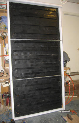
-
Paint the absorber black. I
used an oil base flat black Rustoleum. Black
barbeque spray paint is popular. I'm not sure which is best.

Push the fin tightly onto the PEX.
Any gaps between the fin and PEX should be paper thin and
filled with silicone. |
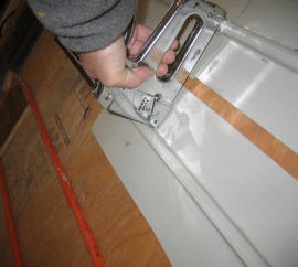
While pressing the fin into the PEX,
staple at about 5 inch intervals.
Note that I should NOT have left any gaps between adjacent fins -- they
can overlap a bit, but no gaps. |
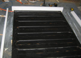
Painted absorber. |
The idea of the extra piece of flat
aluminum under the PEX is to try to go the extra mile in providing a large area
to conduct heat into the PEX and make up for the PEX tubing low thermal
conductivity. The idea is that some of the heat from the fin will be
transferred into this piece and then into the PEX. It probably does not
add a lot of conductive path, but its not much work either.
Try to keep the silicone off the
outer surface of the fin, as you will have to clean it off very carefully before
painting the absorber.
The whole idea of doing the steps above carefully is to make sure that there is
a maximum amount of aluminum in close contact with the PEX -- this helps to make
up for the poor thermal conductivity of the PEX compared to copper. The
silicone is intended to fill any remaining tiny air films that might exist and
is used because it is much more thermally conductive than the air it replaces.
The idea is to make the layer of silicone very very thin so that it does not add
to the poor thermal conductivity of the PEX itself.
Try to keep the PEX runs between
bends straight, especially if you want to have the collector drain back
reliably.
Note that on the prototype, I
miscalculated and left some gaps between adjacent fins. This is bad
because these gaps just reduce the effective area of the collector. I also
got a little wavy on some of the runs that should be straight. You can do
better!
Making the Fins
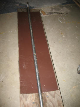
I made the fins using the simple
plywood tool shown below and a 5/8ths inch steel rod. A piece of the
aluminum fin material is placed over the tool, and the 5/8 inch steel rod is
driven down into the groove in the tool. I found that the best thing to
drive the rod down into the aluminum was a full sized sledge hammer.
Holding the sledge as shown in the picture and driving it straight down onto the
rod and fin makes a nice groove and keeps the rest of the fin pretty flat.
Once you get in the "swing" of this, you can do a fin in about 15 seconds.

Simple forming tool made with plywood
A little paste wax in the groove helps. |

Forming the groove with sledge.
Use the end of sledge as shown
to avoid denting the fins. |
Finished groove -- about 15 seconds. |
The material I used to make the fins
is sold by the local lumber yard as soffit material. It is
Rollex
System 3, and comes in 16 inch wide by 12 ft long sheets, and is about 0.018
inch thick -- about $1 per sqft. It is thicker than the
commonly available aluminum flashing material. The added thickness will improve performance.
It also has some pre-formed grooves that can be used to start the grooving
process. This was the cheapest source of aluminum I could find that was of
about the right thickness. The down side is that you have to cut it into
the size you want, but, It cuts nicely on a table saw or electric saber (jig)
saw with ordinary
wood working blades -- you can cut several thicknesses at the same time -- wear
safety glasses.
Aluminum comes in a number of
different alloys and heat treatments, and they all behave a bit differently.
You may have to experiment a bit with the grooving technique.
The fins I made are only 2 ft long
because I had this material left over from the radiant floor project. If
not for this, I would have made the fins long enough to each do one of the
serpentine tube runs.
In the past I used a home made press
to put the grooves in, but the sledge hammer works nearly as well. So, its
probably not worth building something fancier unless you have a lot of fins to
make.
Building the Frame
The collector frame is built from
2X4's with a 2X6 top sill. This is an easy and durable construction.
I dadoed a groove in each of the edge
members to receive the 4X8 plywood absorber. The groove is placed to allow
for the 1 inch of insulation behind the absorber. If you don't have
a dado blade, the absorber could just be placed on a ledger board that you nail
to the inside of the frame.
Note:
This collector is built
with the ledger board approach instead of a dadoed groove, and I think its a
better approach. Its easier, and allows the absorber to be removed if need
be at some future time.
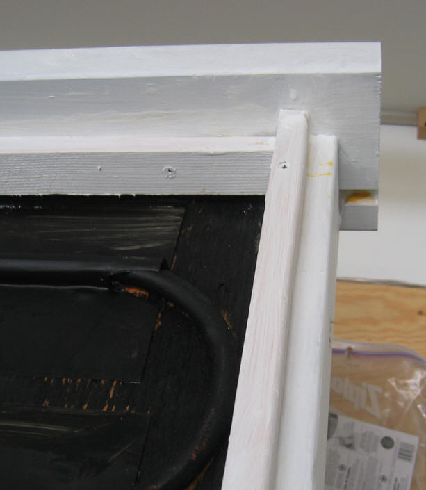
Completed edge frame with
absorber installed. |
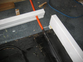
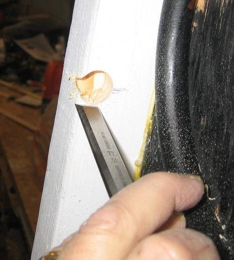
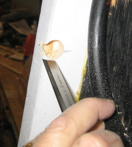
Fit the PEX pipe through a
hole in the edge piece. |
Bottom corner showing the
bottom sill already mounted
to absorber, and edge piece
about to be installed. |
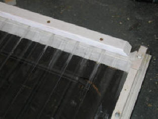
Since I figure on using this in a
vertical or near vertical position, I made the top sill of the collector from a
2X6 so that it extends out over the glazing to keep rain from entering under the
glazing at the top.
The joints on the frame are arranged
such that:
The top sill extends out over the
two side pieces to reduce the exposure of this joint to water.
The two side pieces extend just
beyond the bottom sill to reduce the exposure of this joint to water.
To assemble the absorber
and frame together, drill holes in the edge frame where the PEX lines will be
exiting. Then slide the edge pieces over the PEX and into position against
the plywood. Apply glue or silicone caulk in the edge frame member
dado groove and tap the edge frame pieces into place over the plywood.
Secure with screws -- coated deck screws or stainless screws will prevent rust
stains over time.
Back Insulation
The insulation behind the
absorber is 1 inch thick Atlas R-Board polyisocyanurate rigid insulation board.
Due to the potentially high temperatures at the back of the absorber, it is
probably best to use the polyiso insulation and not use something like
polystyrene.
If you check around, many
lumber yards carry the polyisocyanurate insulation, but they may not know it as
polyisocyanurate. If in doubt ask to go out and look at what they have.
If its polyiso insulation, it will say so on the sheet. It is often tan
colored and almost always has some type of foil or fiber face sheet.
Its only slightly more
expensive than polystyrene, and has a much higher temperature capability.
To install the insulation:
-
Trim the sheet so it
fits into the back of the frame.
-
To hold the insulation
in place, spray some of the polyurethane foam in a can insulation onto the
back of the plywood, and press the insulation board down into the foam.
One brand of the PU foam is "Great Stuff". Be careful -- if you get any on yourself,
you will be wearing it for a week.
-
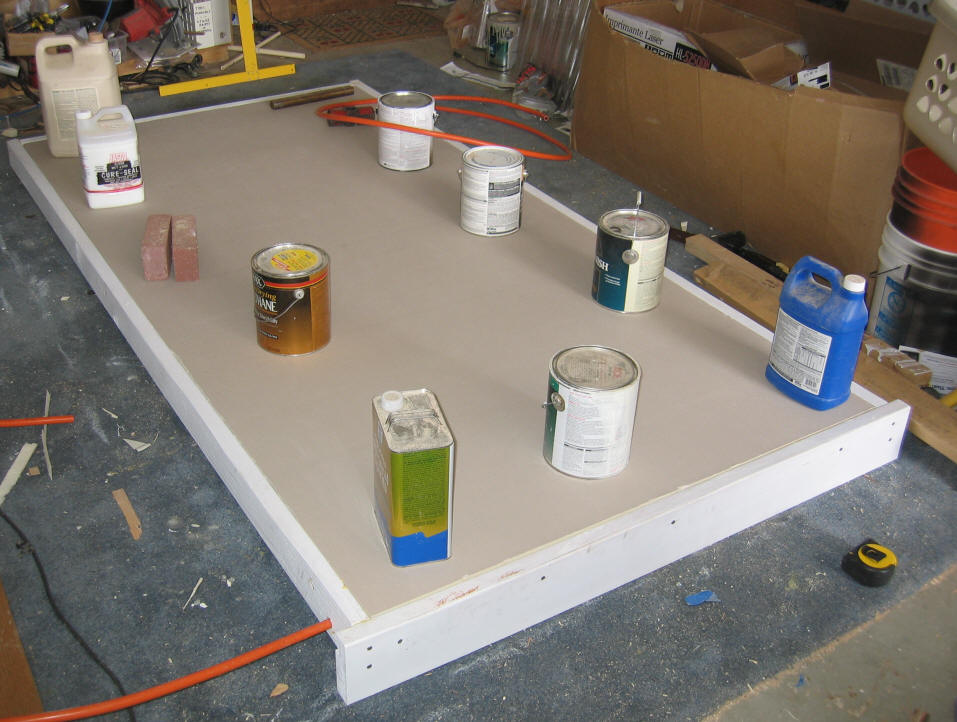
Weight the insulation
board down until the foam in can sets -- it will want to expand.
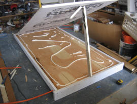
The foam board ready to be lowered
onto the polyurethane foam that acts
as glue to hold it in place. |

Weight down the board to keep
the foam from pushing it up. |
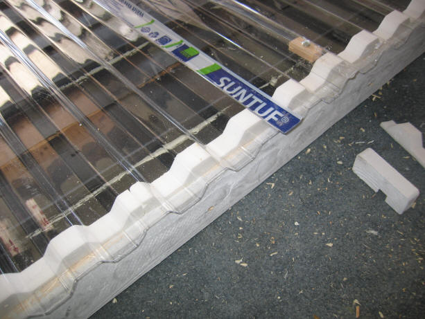
Glazing
The glazing material I used is SunTuf
corrugated polycarbonate glazing. It has a high temperature capability,
good transmission, is very tough, and has a layer to filter out UV. This
is all good for a solar collector. It costs a little over $1 per sqft.
Many Home Depots carry it.

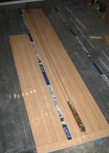
Step 1: Join two sheets of 2X8
ft polycarbonate sheet into a single 4X8 sheet. This is done by
overlapping the two sheets by one corrugation. To bond the sheets
together, I used a bead of clear silicone -- I weighted this until the silicone
set. I then screwed the two sheets together at three places using small
blocks of wood behind the corrugations at the screw locations.
Use a strip of wood under the two
overlapped corrugations to support the back side of the corrugations while the
silicone is setting and there are weights on it.
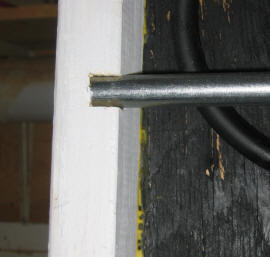
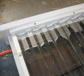
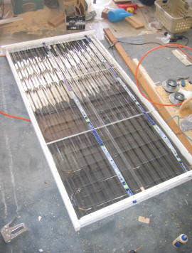
Step 2: Install the two intermediate
horizontal glazing supports. I used half inch EMT electrical conduit for these
intermediate supports. The EMT is good for this, it is straight,
galvanized, and cheap. To anchor each end of the EMT, drill a 3/4 inch
hole in the edge frame that the EMT can slip into (see picture).
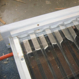
Frame with the two intermediate
EMT glazing supports installed. |
Notch for the EMT intermediate
glazing support. |
EMT intermediate blazing support
installed. |
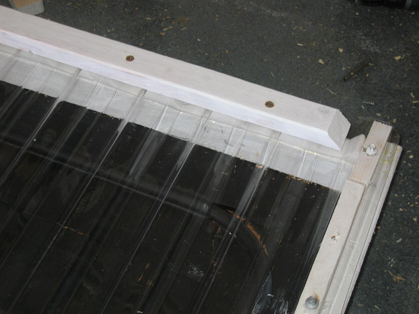
Step 3: Buy or cut some 3/4 by
3/4 inch strips of wood. Mount one of these strips along each of the two
side frame members. Before securing them with glue and screws, make sure
that when you place the glazing panel of over the strips that each strip is
centered in the glazing panel edge corrugations.

3/4 inch edge strip installed along right
edge frame member.
The last corrugation of the glazing sheet
will sit over this 3/4 inch strip. |
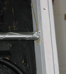
3/4 inch edge strip where it runs
over the intermediate glazing support.
The bead of silicone on the EMT is
to keep the glazing from rubbing
on the metal |
Step 4: Mount another 3/4 by 3/4
strip of wood to the bottom of the top sill so that it will support the "wiggle
strip" used along the top of the glazing (see picture). Install the foam
wiggle strip on the 3/4 by 3/4 strip using a bead of silicone. The top
wiggle strip seals the corrugation openings on the top edge of the glazing.
The top "wiggle strip" which sits on a
3/4 by 3/4 wood strip that is attached to
the bottom of the top sill.
The wood cap strip that is on top of
the glazing holds the glazing in place
against the wiggle strip
Step 4: Install the lower "wiggle
strip" on the lower still. this will seal the corrugation openings on the
lower edge of the glazing.
| |

Lower foam "wiggle strip" in
place
|
|
Step 5: Using screws with EPDM
washers (sold along with SunTuf), secure the vertical edges of the corrugated glazing to the 3/4 by 3/4
vertical strips you installed in step 3. For each screw, with the
glazing in place, drill a small pilot hole through the glazing and into the
wood. The with a larger drill, enlarge the hole through the glazing
material so that it is oversized for the screw. When you tighten the
screw, the EPDM washer should be just barely compressed -- not flattened into a
doughnut shape. If your drill has a torque clutch, try finding a setting
that just barely compresses the washer.
All of this care with the holes is
supposed to allow the polycarbonate glazing to move a little with thermal
expansion -- otherwise cracks may develop at the screw locations.
Step 6: To hold the glazing against
the wiggle strips at the top and the bottom, cut strips the width of the
collector. Place one strip over the glazing at the top edge of the
collector, and screw it to the underlying frame in several places. This
strip will uniformly press the glazing into the foam wiggle strips.
Do the same for the bottom wiggle
strip.
In the past, I have secured the
glazing at the top and bottom with a bunch of the washer screws. This
works OK, but it takes a lot of screws and does not achieve the uniform pressure
that using the external strips as described above does.
Top of collector showing the
top "wiggle strip" with the external
wood strip pressing the
glazing into the wiggle strip.
|
Bottom of collector showing the
lower wiggle strip with the external
wood strip pressing the glazing
into the wiggle strip.
The 3/4 by 3/4 edge strip with
a couple of the EPDM washer
screws if visible on the right. |
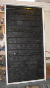
All the glazing in place
and secured. |
Final Thoughts
Even though the materials used to
make the collector are fairly light, the collector ends up weighing 117 lbs --
so, if your name isn't Arnold, you may want some help getting it in place.
There are all kinds of other
construction possibilities. The collector could be larger in either or
both directions. A multi bay collector could be built, which would save
some on materials and reduce heat loss. It could be triangular.
I did not use any side insulation,
which might be a good thing to do, although the wood provides some insulating
value.
Be sure to allow some downward slope
on each of the straight runs of the serpentine PEX tube. The
prototype with minimal slope on each serpentine straight run is draining back
reliably. See this drain back test
to better understand what this is about.
There are some silicone caulks
formulated with fillers to increase thermal conductivity -- this would be a
good idea to use if you can find them -- (please let me know if you find a good
source). I
plan to test several different materials that are commonly available and might
have better thermal conductivity. Some have suggested the use of the
thermal compounds used in the electronics industry, or the use of the aluminum
filled gutter sealant -- these might be good things to do, but I have no
experience with them myself.
I'm inclined to think that if you do
a good job of making the groove fit snuggly over the PEX so that the
layer of silicone is paper thin, that the conductivity of the silicone won't
make a whole lot of difference.
Things to think about changing:
- Add insulation along the sides
of the frame.
- Make sure there are no gaps
between the fins.
- Cover the PEX at the ends of
the bends so that it is not exposed to sunlight (although the paint and
SunTuf and black paint should already provide good protection).
- Support the absorber on a
ledger board rather than using a dado groove.
- Try to find a silicone caulk
that is filled to achieve a higher thermal conductivity.
Things not to change:
- Use good glazing -- either
polycarbonate or glass -- PVC and the like will melt
- Use silicone caulk -- it
withstands high temperatures and remains rubbery
- Use
PEX-AL-PEX, not PEX
- Using the thicker (0.018 inch) material for
fins.

Ready for testing.