Search
The Renewable Energy site for Do-It-Yourselfers
Adventures in
Measuring Airflow for A Solar Collector
|
Scott and I
and others have been looking at a way to accurately determine the performance of
several solar air collector absorber designs.
One of the things you need to
do this is an accurate way to measure airflow through the collector.
Since we are all cheap, it would be nice if the airflow measurement
method was inexpensive.
This page describes some
attempt over the last week to work out a way to measure collector
airflow without spending a fortune.
If you are trying to measure
airflow on a budget, the methods on this page may be of some help (or
not).
If you have any thoughts on
this, please let us know.
In addition to what is shown here, Scott is working on a method that
uses the voltage generated by a PC type 12 VDC fan that is immersed in
the airflow generates -- this looks interesting.
Back to the Solar Air Heating Collector test
program home..
|
|
This page looks at the results of
trying three different techniques to measure airflow:
- Hot Wire
Anemometer...
- Fantech IRIS
air flow measurement damper...
- A very simple
pitot tube...
- The Big Bag
method...
- The
Contractor Garbage Bag method...
---
-
Collector pressure drop measurements...
All of these tests were done on this
"reference" collector, which is meant to be the
baseline to compare other air heating collectors against...
For the latest air
flow method I'm using see...., and the
downspout collector
test...
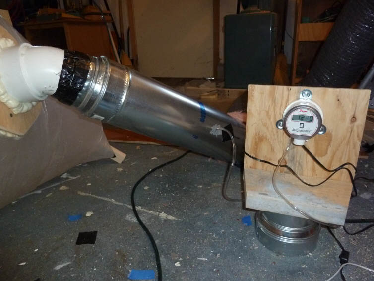
Setup for Flow Tests
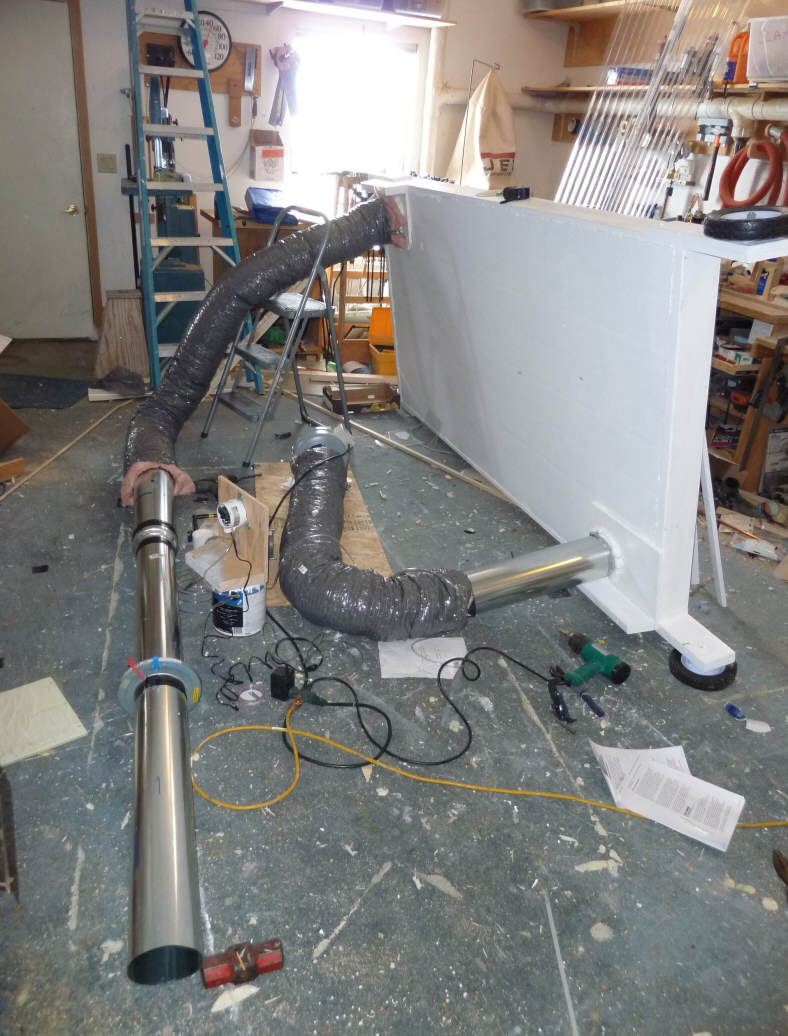
A little hard to see all this, but
- Collector is on its side to the
right -- we are looking at back of it.
- outlet duct is the one at the
bottom (near the wheel)
- Fan is at the end of the 6 inch
ducting coming out of the collector exit -- fan is pulling air through the
collector.
- inlet duct is at the opposite
top far end of collector.
- The inlet duct starts at the
sledge hammer head, and goes through these steps: 5 inch duct to the
Fantech IRIS damper (with the blue and red bits; 5 inch duct to a 5 to
6 inch duct transition fitting; 6 inch flex duct up to the actual collector
inlet.
- The fittings right at the
collector are 5 to 6 inch duct transition fittings, so the hole in the back
of the collector is 5 inches in diameter, but transitions to 6 inches
immediately as it leaves the collector.
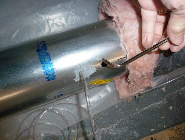
There are ports to measure the duct
static pressure in the outlet 6 inch galvanized duct section (pic below), and
also one in the 6 inch galvanized duct portion of the inlet duct.
The pressure drop across the
collector is measured as the difference between these to static ports.
The static port is basically just a
hole in the duct wall that you can measure the static pressure right at the duct
wall with.

Pressure differences are measured
with this Dwyer Magnasense manometer.
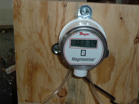
It registers down to 0.001 inch of
water, but is a bit shaky measuring less than 0.01 inch differences.
Fantech IRIS
Damper Flow Measurements
This is a relatively inexpensive
gadget sold by Fantech for the purpose of measuring and setting airflow.
Seems like a nice simple solution,
but the results so far have been disappointing.
Maybe the you will see something
wrong in the way I'm using it?
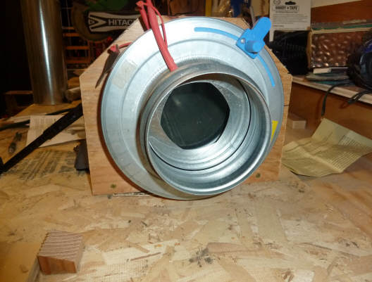
The blue handle adjusts how far closed the iris is. You can see the
iris inside the duct in pic above.
The iris damper causes a drop in the
duct static pressure which is proportional to the flow rate through the duct.
The pressure drop is measured at the
two red static ports on either side of the damper by hooking up a manometer to
the taps.
The further the close the iris, the
greater the pressure drop.
The flow rate is:
Flow Rate = K * sqrt(dP)
Where K is the K-Factor -- it just
depends on where you set the iris -- you read it off the scale on the damper
opposite where you place the blue handle.
dP is the pressure drop you measure
across the damper in inches of water.
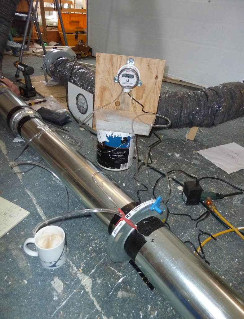
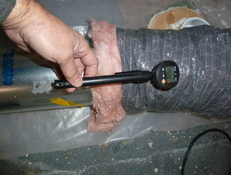
This is the setup for measuring the
flow with the iris damper.
The manometer is showing a drop of
0.068 inches of water across the damper.
I believe that this was the
measurement done with the blue handle set to a K-Factor of 100, so the flow rate
is:
Flow Rate =
(100)*(sqrt(0.068)) = 26.1 cfm
I tried measuring the flow rate with
the iris damper from all the way open (K = 280) down to its most closed position
with K = 50.
As the damper goes from fully open,
to its most closed position, the pressure drop across the damper increases, and
the flow rate decreases due to the flow resistance of the damper.
But, the flow rate as calculated from the formula above stays nearly the same --
odd.
These are the values measured:
|
Iris Damper |
|
|
K factor |
dP inches |
Qiris cfm |
|
280 |
0.007 |
23.4 |
|
150 |
0.02 |
21.2 |
|
100 |
0.067 |
25.9 |
|
80 |
0.108 |
26.3 |
|
50 |
0.2 |
22.4 |
This is really puzzling.
It shows very low flow rates -- only
about 25 cfm -- much less than the other methods.
And, the flow rates do not vary much
as the iris is closed, while the other methods show a good deal of velocity and
flow rate reduction as the iris is closed.
So, don't really know what to make of
this -- it appears that the damper is not even close on flow rates. Not
sure if there is something wrong in my setup, or something wrong with the
damper, or ??? Any ideas??
I plan to email Fantech about this on
Monday and see if they have some advice.
Update Dec 2: I tried a 2nd IRIS
damper I had on hand with the same result.
I emailed Fantech support a couple days ago -- no reply yet.
The thing I like about using the iris
dampers for flow rate measurement is that its nice and simple and not too
expensive.
One thing I had not thought about is
that by the time the damper is closed far enough to create a pressure drop that
can be measured by a not to expensive manometer, its a fairly large pressure
drop, and the fan has to be large enough to supply this drop. The end
result is that you might have to have one fan for testing (with higher pressure
capability) and a different fan for regular use.
Hot Wire
Anemometer
I have a Test Velocity Stick hot wire
anemometer, which I used for this go at flow rate measurement.
For each setting of the iris damper
(above), I also measured the duct velocity in the 6 inch section of duct with
the hot wire.
The results are in the plot below.
They seem sensible to me.
To get the readings, I drilled a half
inch hole in the duct wall, and I insert the hot wire probe into the hole so
that it sits about in the center of the duct.
The flow in the pic below is left to
right, and there is a several diameters stretch of straight duct to the left of
the hot wire reading hole.
And, since the fan is pulling air,
and is all the way on the other side of the collector, there is no fan induced
swirl that I saw on previous measurement setups.
Hard to see in this pic, but the hot
wire probe drops straight down into the duct from just to the left of where my
hand is.
I mark the penetration depth with a
piece of tape on the hot wire tube.
The problem that I have always had
with this hot wire meter is that the readings vary a lot with time. If you
are reading a flow with an average velocity of (say) 400 fpm, you might get
readings over 30 seconds that vary from 360 up to 440 fpm. So, even if you
average 10 or so readings, it does not give a lot of confidence that you have
really nailed down the velocity closely.
Not sure if this is a characteristic
of the this particular hot wire meter (not enough filtering?), or its a common
thing on hot wires?
The hot wire anemometers are also
kind of pricey at about $200 for the cheaper ones.
I plan to call Testo and ask them
about this high variability in readings thing, but even if they have a good
suggestion, it seems like its too expensive a solution.
The other thing is that the hot wire
gives a velocity in the center of the stream, and you have to factor that to
account for the drop off in velocity as you go out towards the edge of the duct. Our duct speeds are such that the
flow is fully turbulent, so the velocity profile is pretty flat, and the
correction is not to large, but its just another thing to contribute error.
Very Simple
Pitot Tube
I had sort of dropped the pitot tube
as a potential flow measurement method because our duct velocities generate very
low Pitot pressures that would difficult to read without very fancy instruments.
But, given that the hot wire and the
iris differed by so much, I wanted another method to check against the two.
I used the very very crude Pitot tube
that comes with the Dwyer 460 air velocity kit. Its basically just a 1/4
inch diameter L shaped tube where the open end of the tube faces into the
flow. You measure the difference between the static port on the duct
and the Pitot tube with the manometer, and then calculate the duct velocity from
the pressure difference, and then the flow rate from the duct velocity.
The simple Pitot. The L
shaped end goes into the hole in the duct just below pointed into the flow at
the center of the duct.
The matching static pressure comes from the static port just in front of the
hole in the duct.
This is the same hole that was used
for the hot wire measurement.
These Pitot tube measurements were
pushing the capability of my manometer, and I'm sure the crude design of the
tube did not help either, but the results actually agree pretty well with the
hot wire, and are dramatically different from the iris damper. So, I'd say
that this tends to confirm that the iris damper measurements are just not
working.
Results
The graph just below shows how the 3
methods compare on their estimates of flow rate through the collector.
Vertical axis is flow in cfm
Horizontal axis is the pressure drop
through the collector.
Red are flow rates as estimated with
hot wire anemometer.
Blue are flow rates as estimated with
the iris camper.
Green are flow rates estimated with
the crude Pitot tube.
Big Bag Method
So, none of the methods above are
very satisfying.
I got to wondering if the
technique
where you time how long it takes to fill a garbage bag would work better.
One problem appears to be that for
even a big garbage bag the fill time is quite short, and would be hard to
measure accurately.
So, I'm having a go at building a
bigger bag from poly sheeting and duct tape.
The bag is a cylinder, a bit over 3
ft in diameter, and about 10 ft long.
It has a volume in the area 60 cubic
feet, so it should take almost a minute to fill.
If this bag approach works, then it might
be easier just to use a length of this "layflat" poly ducting:
http://www.tombling.com/ducting/
to build the bag -- 20 ft of 24 inch
would do it.

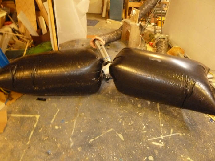
The big bag -- its a 10 ft wide
length of poly where the edges are duct taped together to make a cylinder.
Ends are closed off by clamping
between two pieces of wood and duct tape.
The fill fitting is sandwiched
together between two pieces of plywood.
I used the Gorilla brand duct tape --
have to say its pretty impressive stuff :)
---
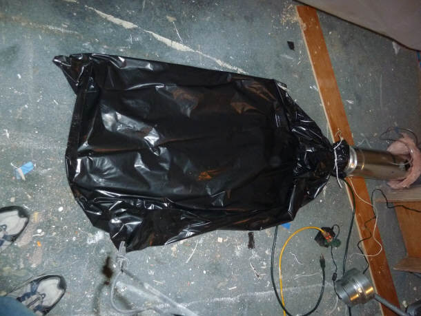
First Air
Did the first inflation -- that was
fun!
Measured a few things and did a
couple rough timings.
Inflation:
It inflates nicely. Takes about
48 seconds to full.
The poly and duct tape will take the
full fan stagnation pressure of 1.2 inches of water with no apparent strain.
No leaks detectable with the hand
test on any part of the bag.
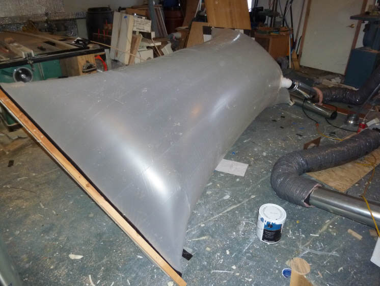
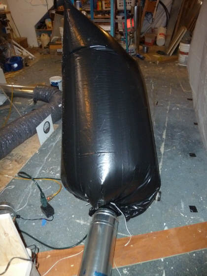
Fully inflated -- left it this way for about 5 minutes -- no problems.
Static pressure goes up to 1.23
inches of water with full inflation.
The Pictures below show the shape of inflated bag:
Need to figure out how to calculate
the volume.
Volume for now:
Diameter is (119 inches)/Pi = 38
inches.
Inflated length is 120 inches for
wood strip to wood strip.
Assume that end shape effectively
loses 10 inches of full diameter volume, so effective full diameter length = 120
-10*2 = 100 inches
Rough volume =
(38^2)*(0.785)*(100)/1728 = 65.6 cf very rough
Flow Rate
Using the rough volume estimate
above, this says that with a 48 sec inflation, the airflow = 65.6 cf/ 48 sec =
1.37 cf per sec, or 82 cfm.
This agrees quite well with the hot
wire calculated fill rate with the iris full open (the iris was out for the bag
test).
Back Pressure:
One concern is that the filling
balloon might cause some back pressure that would slow the flow rate down.
I hooked the manometer up to the
static port near in the 6 inch duct just before the inflation fitting.
Inflation duct (collector exit
duct) free in room
0.09 inches water
Duct connected, bag filling, bag
loose, wood strips on floor
0.09 inches water
Bag lifting wood strips off the
floor and balloon nearing final shape
0.14 inches water
Bag full flow stagnated
1.23 inches water
So, for the first half plus of the
inflation, the bag causes no back pressure.
As the wood strips that terminate the
end of the bag are being lifted off the floor, and bag is nearing its final
shape, a back pressure of 0.05 inches of water ( 0.14 - 0.09) is present.
Based on the tests above, this might slow the inflation rate for the last part
by as much as 10 cfm.
I later hung the bag from the ceiling
to try to reduce the backpressure that occurs as the wood strips are lifted off
the floor.

This works very nicely, and the ramp up
in back pressure as the bag gets near full does not start until about 3 seconds
from the bag being full.
Here
is an avi video of the inflation to download and play on your PC ...
(4mb)
In this breathtaking video, the Big
Bag is hooked up to the exit duct of the collector. It takes about 50
seconds to blow up, and you can see how easy/hard it is to judge the full
inflation point -- seems pretty easy to me.
Yes -- I know my shop needs a good
cleaning !
Extra Large
Contractor Garbage Bags
This approach uses one or two off the
shelf 55 gallon garbage bags instead of making an extra large bag.
I found a couple of extra large
"contractor" garbage bags purchased some time back for some forgotten reason.
They are a nominal 55 gallons (7.35 cf). I decided to just try one of
these.
To put something together quickly, I
just tied the bag onto the end of the duct, and then switched on the fan to
start the timing. This is not ideal in that the blower takes a little bit
to ramp up to full speed, but it gives a pretty good idea.
55 gallon bag attached and ready to
start inflation.
Inflated.
The time was about 9.3 seconds.
If the flow was 82 cfm, the time
should have been (7.3 cf/65 cfm)/60 = 5.3 seconds. The longer actual time
was very likely due to the blower ramp up time.
So, some kind of fixture that could
be attached to the bag, and then very quickly placed over the end of the duct
with the fan already running would be needed -- something like what I have on
the Big Bag.
Judging when the bag is full is
easier than it would seem, since the bag sort snaps into the fully full
position.
I would guess that one could get to
better than half a second -- maybe even better.
So, this is less accurate than the
Big Bag, but does seem feasible, and probably better than any of the instrument
approaches.
If we could find some even larger
bags -- maybe around a hundred gallons, I think this would work fine.
Again, there is the problem of
arriving at an exact (or fairly exact) actual volume for the bags.
Here is an .avi video of the 55 gallon bag inflating to download and play on
your PC... (1 mb)
In this thrilling video, the bag is
already hooked up to the collector outlet duct. I plug in the fan to start
the inflation and say "go".
You can get an idea of the timing and
how easy the full inflation point is to see.
One advantage of the garbage bag
approach is that it is reported that the actual volume of a 55 gallon bag is
pretty close to 55 gallons, so for rough flow measurements, you could just use
the nominal volume.
Another approach that would be
workable with the 55 gallon bags is to fill a bag with packing peanuts, and then
pore the peanuts out into a box to measure the volume. One could start by
putting boxes or tubes into the bag first, and then use peanuts for the last
part.
I think that with a little thought
one could also do a pretty accurate volume calculation from dimensions -- maybe
treat it as a series of ellipses, and then manually integrate over the ellipses?
It would be fairly easy to mark (say) 5 inch sections along the long axis of the
bag, and measure the major and minor axes and perimeter of each section.
Dec 2 -- tried two of these 55
gallon bags together
Since one 55 gallon bag fills a
little fast for accurate timing, I tried using a 4 inch plastic Tee fitting to
hook two of the 55 gallon bags to.
This gives 110 gallons or 14.7 cf.
Fill time is about 16 seconds, which
allows for pretty accurate timing.
The bags are attached to the straight
through Tee fittings with nylon wire ties.
The worm gear type metal clamps would
probably be better than wire ties, but I did not have any of that size.
So, this is a pretty easy solution
for anyone to put together with easy to fine parts.
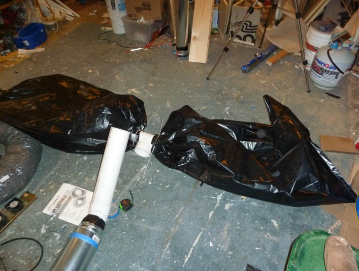
The two 55 gal bags attached to 4 inch plastic Tee with nylon wire ties.
The open leg of the Tee can be quickly placed over the open end of the 4 inch
plastic pipe/duct.
Fully inflated.
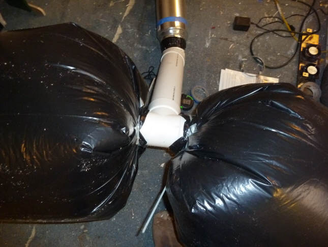
Closeup on the Tee to bag attachment.
Jumbo Storage Bag
This is a large bag that our local
moving and storage place had.
It is 60 inches by 108 inches.
It inflates to a cylinder with a
diameter of (2*60)/ Pi = 38.2 inches = 3.18 ft
The inflated effective length is
about (roughly) 84 inches ( 7 ft).
Volume = (3.18^2)*0.785*7 = 55.6 ft
-- almost as large as the "Big Bag"\
Its made by Chateau Products, inc
http://www.greatlittlebox.com/products/chateau/
Cost was $3.25 per bag with minimum
order of 2.

This is the 60 by 108 inch bag tied
off to a 4 inch plastic pipe coupling.
The coupling is quickly placed over
the end of the 4 inch exit duct to start the fill process.
Back pressure during filling was
minimal (0.01 to 0.02 inches of water) right up until the end.
The onset of the pressure rise at the
end of the fill was very rapid, and one could use this to stop the timing if one
had a sensitive manometer. But, timing the end by just looking at the bag
was also quite precise.
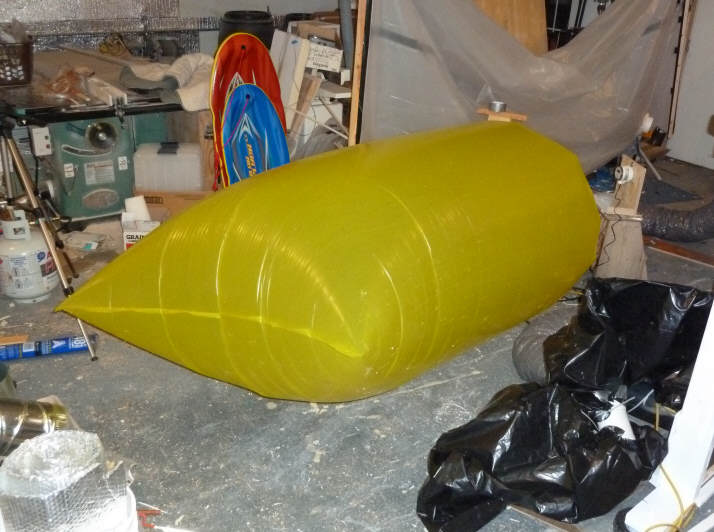
The full bag.
The 2 mil plastic is fairly
lightweight, and this bag has to be treated with some care to avoid damage.
Collector
Pressure Drop
I also measured the pressure drop
through the collector for all the same iris settings where flow rates were
measured.
The pressure drop was obtained by
putting the tube from static duct pressure port on the inlet side of the
collector to one port of the manometer and hooking the tube from the static port
on the outlet end of the collector to the other manometer port. Since both
ports are located in 6 inch diameter sections of the duct, the velocity head
should be the same, so the change in static pressure should be the actual
pressure drop?
Here are all the data measurements
with the collector pressure drop being the left column:
| |
|
Iris Damper |
|
Hot Wire Anemometer |
Pitot Tube |
|
|
dPo |
|
K factor |
dP inches |
Qiris cfm |
Veloc fpm |
Qhotwire cfm |
dP inches (4) |
Veloc fpm |
Qpitot cfm (5) |
|
0.815 |
1 |
280 |
0.007 |
23.4 |
480 |
84.8 |
0.015 |
451.5 |
96.1 |
|
0.800 |
2 |
150 |
0.02 |
21.2 |
470 |
83.0 |
|
|
|
|
0.788 |
3 |
100 |
0.067 |
25.9 |
|
0.0 |
0.012 |
404 |
86 |
|
0.762 |
4 |
80 |
0.108 |
26.3 |
370 |
65.4 |
|
|
|
|
0.710 |
5 |
50 |
0.2 |
22.4 |
300 |
53.0 |
0.011 |
386.9 |
82.4 |
Note that the pressure drops are
pretty high. A lot of fans would have trouble producing the about 0.7
inches of water pressure drop that goes with getting the flow up to about 2 cfm
per sqft of collector.
It makes me wonder if the 1 inch flow
channel height is not a bit to shallow, or if the baffle arrangement is not to
agressive?
Gary November 28, 2010, Dec 2,
2010