Search
The Renewable Energy site for Do-It-Yourselfers
Knick's Solar
Water Heating System -- Collector Construction
| This page provides the detailed construction for the collectors for
Knick's solar water heating system. The collector design includes some
new wrinkles that may be just right for your needs.
 |
|
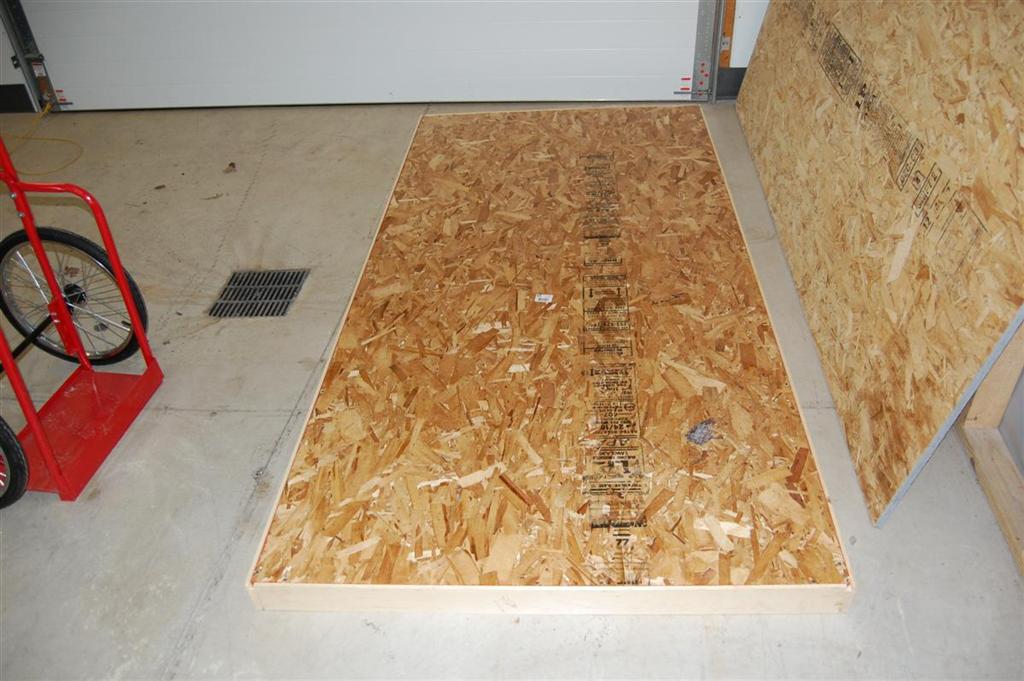
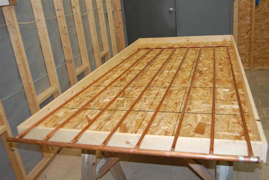
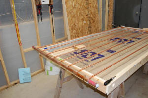
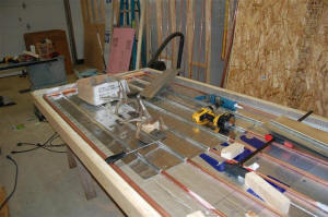
Knick used three collectors, each
about 4 ft by 8 ft.
Collector Box
click on pictures for full size

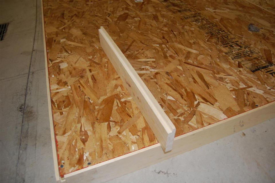
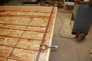
Screwing OSB to collector frame. |
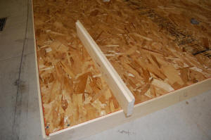
This how the frame looks ready to receive
the OSB back. |

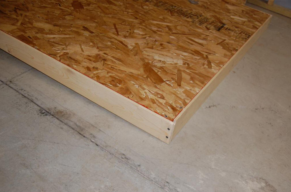
Collector box corner from back. |
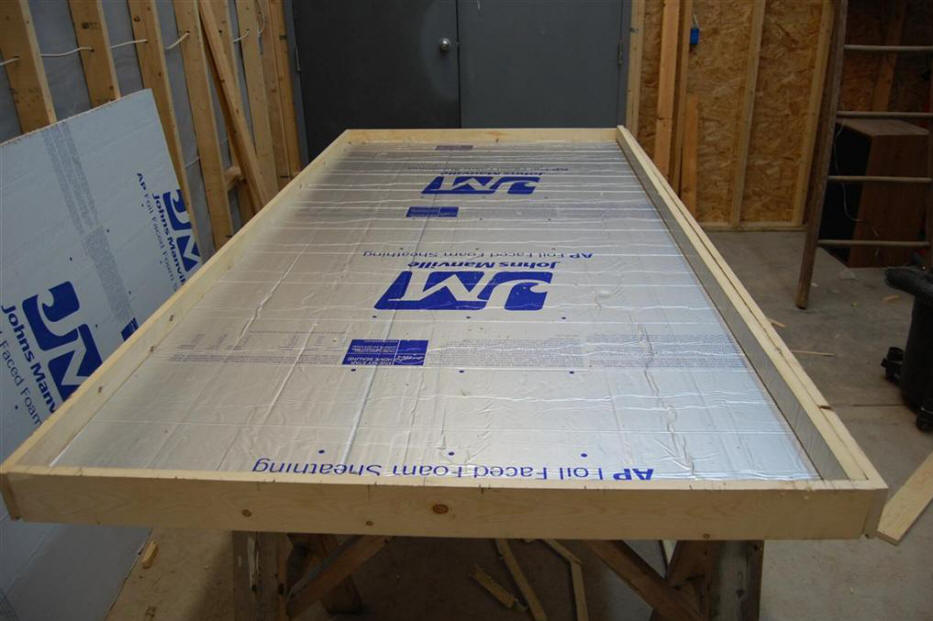
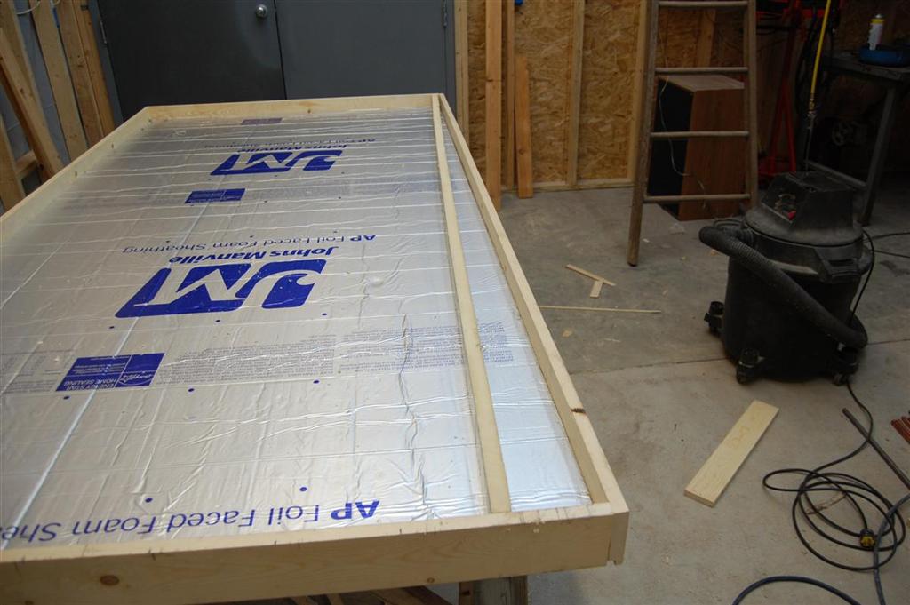
The frame box is made with
1 by 4 inch lumber.
The back of the frame is rabbited for so that the 7/16 inch OSB back board will fit flush
with the back of the frame. Each collector box is 4 ft wide by 8 ft tall.
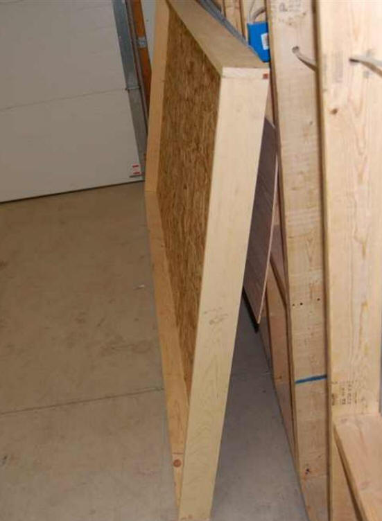
Note that the collector boxes will be protected from the weather by the
aluminum trim shown on the Collector
Installation page.
| |
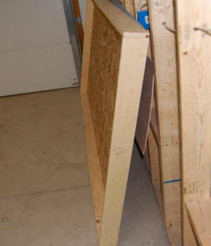
One of the 4ft by 8ft collector boxes. |
|
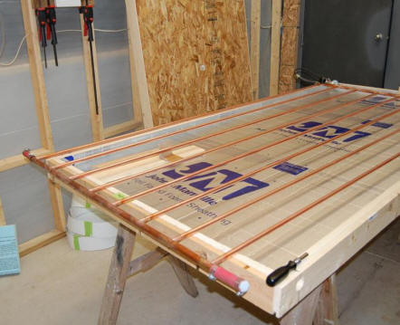
Building the absorber
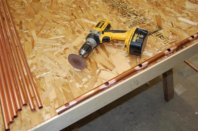
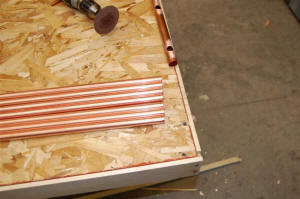
The absorber is made from copper pipe
with aluminum fins used to transfer the solar heat into the pipe.
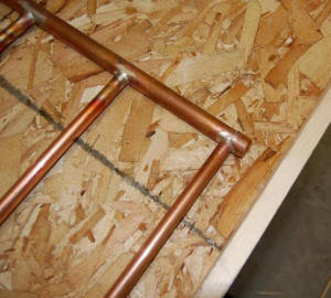
The manifolds are 3/4 inch copper
pipe and the vertical riser pipes are half inch copper pipe.
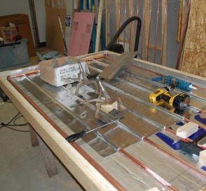
Manifold
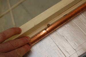
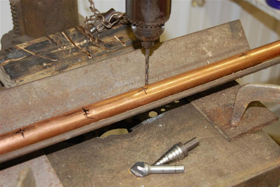
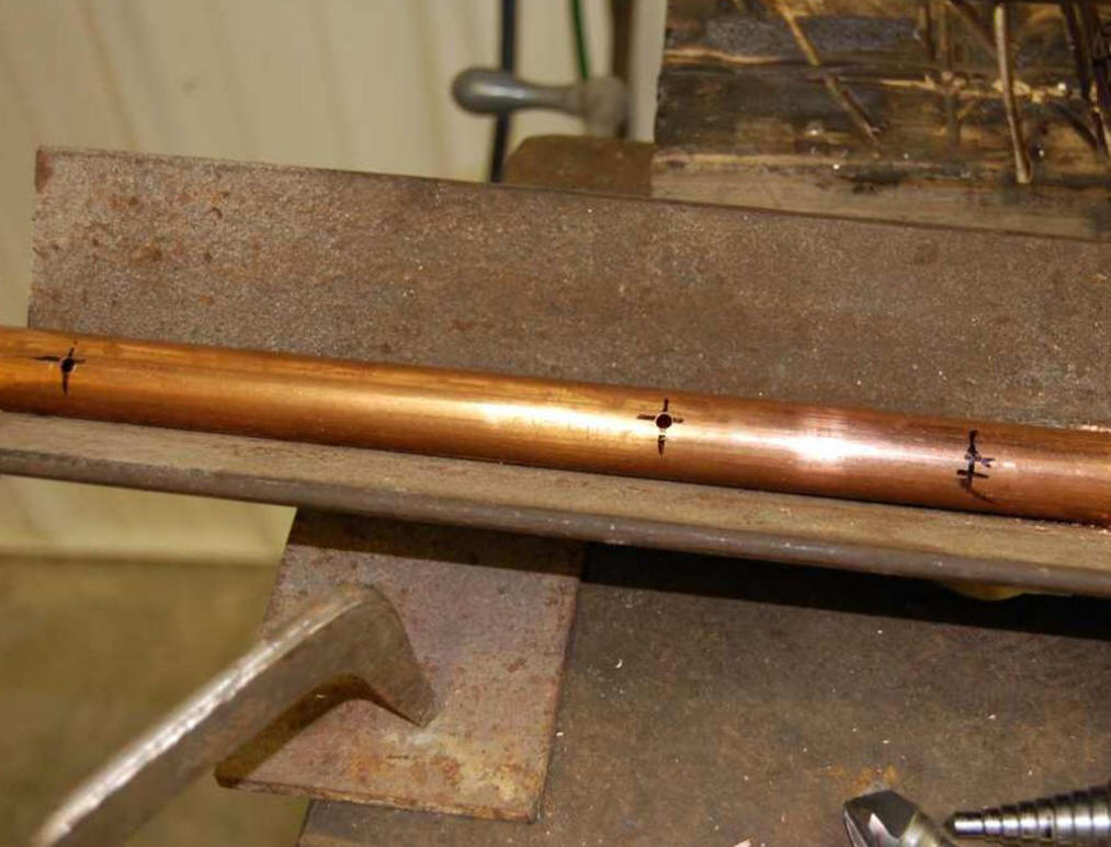
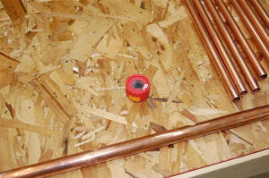
This is how I marked the centerline to
keep all the holes straight. The hole locations
for the risers are then center punched.
|
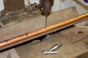
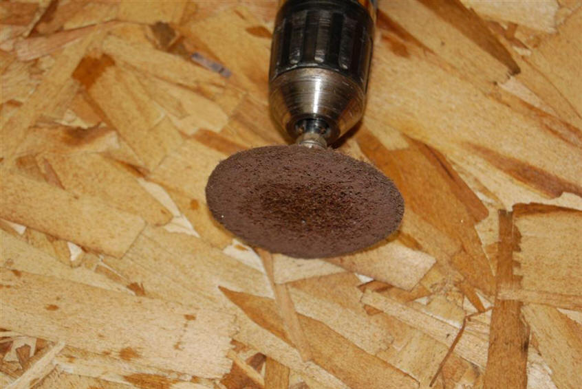
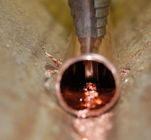
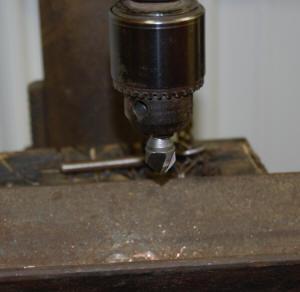
Started manifold holes for risers with a 0.188
inch pilot hole. Next to the step drill, then to
the 0.625 chamfer bit. |

Manifold after drilling the pilot holes that
the risers will fit into. These holes are
enlarged to fit the risers as described in the
next couple pictures.
|

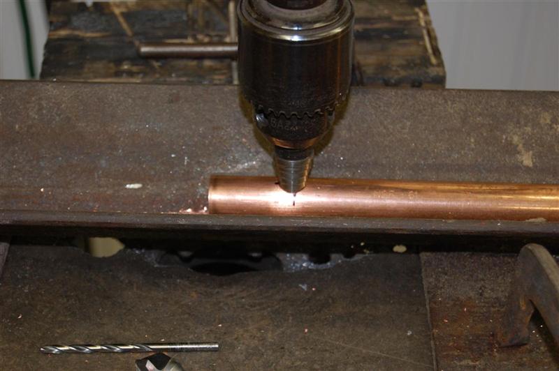
Using the step drill to enlarge the hold for the
riser in the manifold. |
As you can see, the step is a bit long.
You could cut it off. |
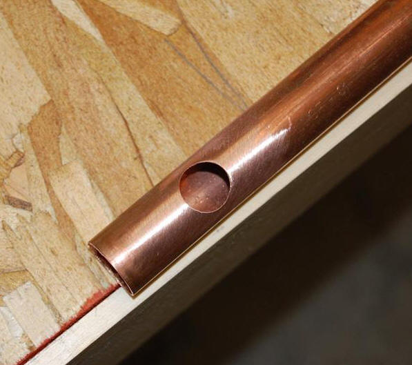
Chamfer bit used to finalize size of holes in
manifold to fit the riser tubes. |

Final hole makes a nice fit to the half inch
copper riser pipes. |
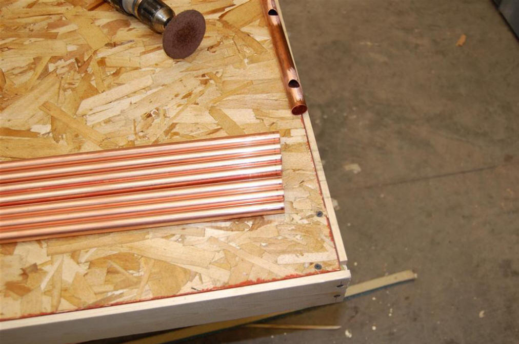
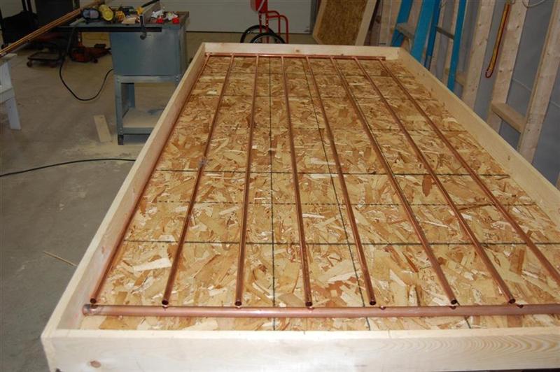
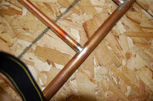
Risers are cut to unequal lengths to allow
the manifold to slope down toward the supply
side for good drain back. |
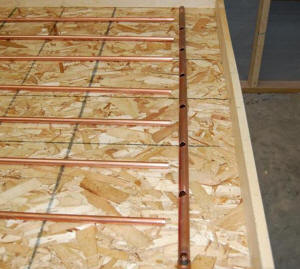
Header and risers set up for test fit. |
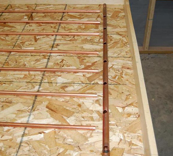
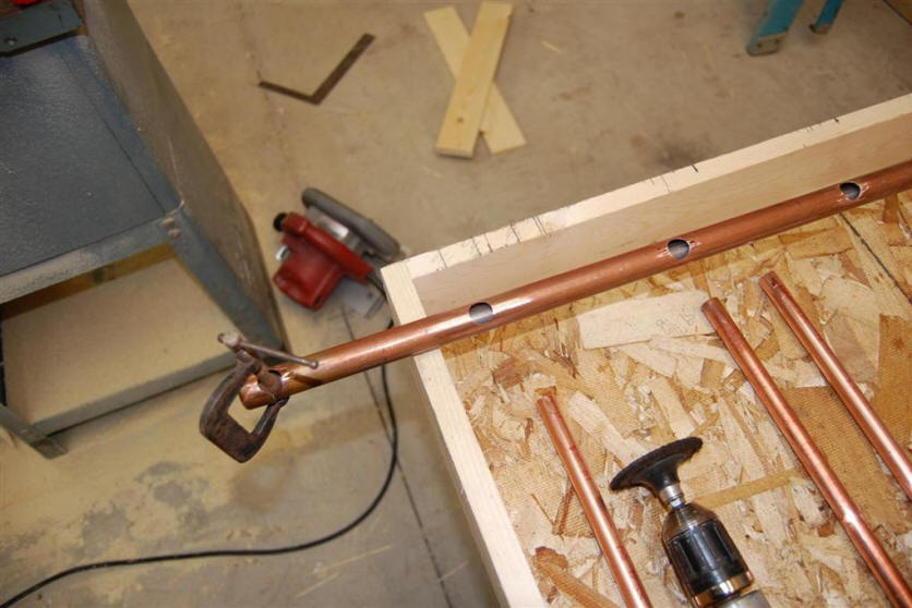
The manifolds are very carefully drilled at each riser location with holes
that are a snug fit for the half inch riser pipes. After careful cleaning,
the riser pipes are pushed into the holes in the manifold. A steel rod
that is temporarily placed inside the manifold pipe acts as a stop to insure
that each riser penetrates the same distance into the manifold.
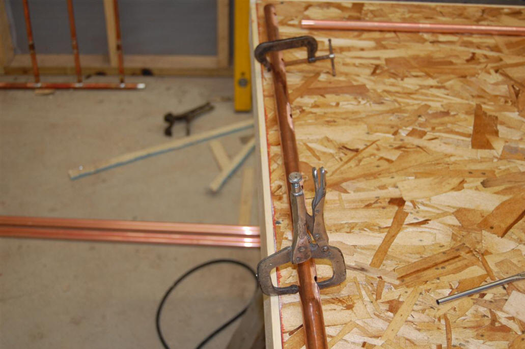
I used a solid piece of steel bar to keep
the riser pipe penetration into the header
the same for all risers. |
|

Once I inserted the steel rod, I clamped it
to hold it on the bottom of the riser.
|
Soldering the Absorber
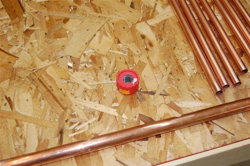
Oatley makes this brush for cleaning the
tube ends. |

This is what I used to clean up and debur
before soldering. Made by 3M. |

Header cleaned and ready to solder. |
Since this is a drain back system, the manifolds MUST slope down toward the
corner that the supply pipe comes into. If the manifolds don't have some
slope for drainage, the water won't drain out of the collector when the pump
stops, and water left in the collector can freeze and split the copper pipes.
For this collector, the riser slope is provided by cutting each riser a little
shorter as you go across the manifold -- this automatically builds some slope
into the manifold for drainage. About 3/16ths of an inch per ft of width
is a good slope to use.

Getting everything cleaned and ready
for solder.
|

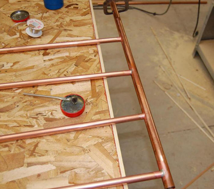
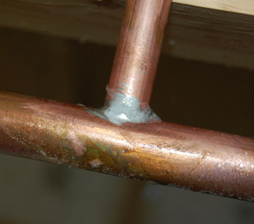
I just tack solder one side to hold everything
in place first. |

Close up of tack solder. |
| |
I then flipped the absorber grid over and
soldered the other side. |
|
Careful cleaning and fluxing is the key to good solder joints, so take the
time to clean all the joint surfaces carefully.
After cleaning and fluxing, the riser pipes are pressed into the manifold
pipes, and soldered in place. These riser to manifold joints are critical
to the integrity of the collector and must be made and soldered carefully.
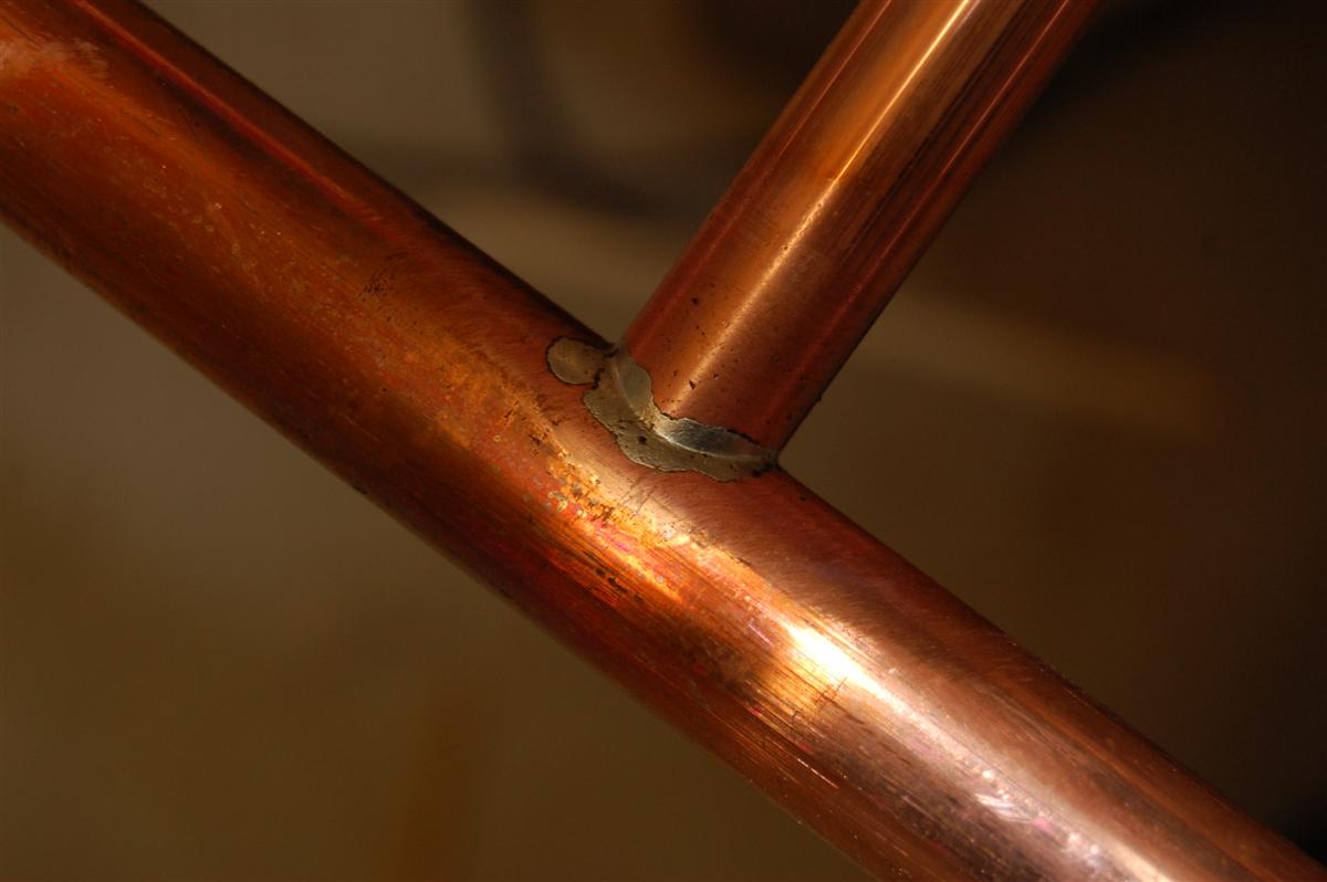
I would not solder joints again with out that tool (tee
expander) to make a tee in the header or unless I used fittings. I'm
not sure if my way will be long lasting.
Manifold Connections

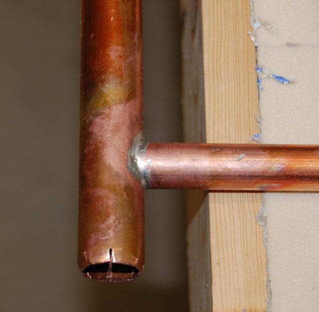
I notched the end and tapped the segments
in toward the center to make it easier to
slip the heater hose on. |
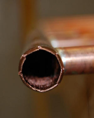
End view of manifold of notched manifold
ready for heater hose.
|
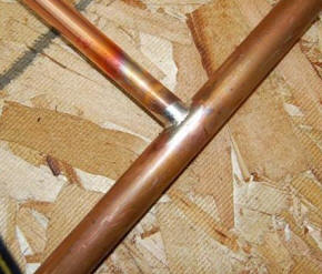
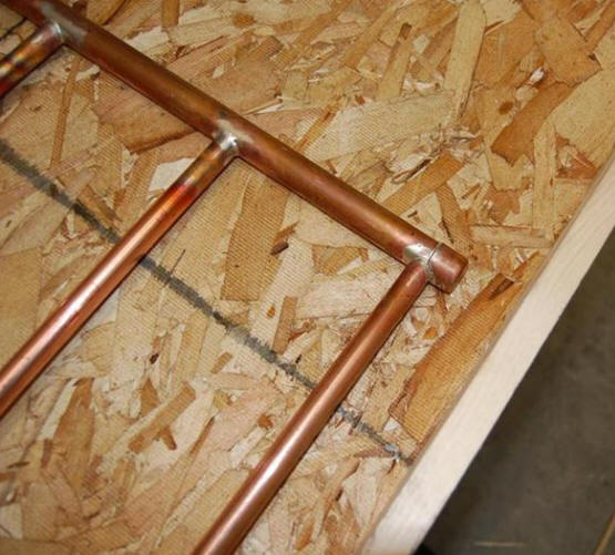
Some of the finished joints. |
The top (and bottom) manifolds
for all three collectors must be connected to each other so that fluid can be
circulated to all three collectors at the same time. High quality heater
hose is used in this collector to make the manifold connections. The
heater hose is made for exposure to high temperature water. The heater
hose has the advantages that it makes it easy to make the connections (no
soldering), and also has the advantage that the hose will accommodate a little
bit of misalignment.
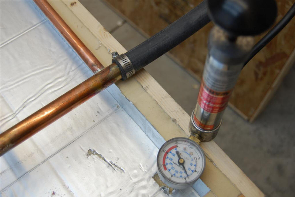
Pressure Testing

Ready to pressure test |
Setup for pressure testing of absorber grid
for leaks. |
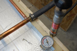
Pressure testing for leaks -- I used about 10
psi for the leak testing. |
| |

A leak |
|
It is very important to pressure test
the collector copper pipe grid before installing it -- its a real pain to find
leaks after everything is installed.
Installing the Insulation

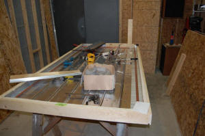
Test fitting the absorber grid to the collector
frame. |

Fitting the 1 inch the high temperature
(polyisocyanurate) insulation to the box. |

Fitting the foam insulation boards to the
sides of the collector box. |
Installing the Pipe Grid and the
Fins
Applying the grooved aluminum fins
over the copper riser tubes. |
|
I used silicone caulk between tubes and fins
for corrosion protection and heat transfer.
Grooves in fins must be clamped in very
snuggly against the copper tubes for a good
thermal connection. |
Aluminum fins that are about 6 inches
wide are used to transfer the incident solar heat energy into the copper riser
pipes. The fins are grooved down the middle so that they fit snuggly over
the riser pipes. For good performance with 6 inch wide fins, the thickness
of the fins should be about 0.018 inch (or more).
More information on various approaches to making or
buying the fins, and on fins performance factors here...
I used
Tom's fins and tools like he did. I actually wanted the fins pressed a
size bigger but got the standard fins for 1/2" copper ( miscommunication) so I
spread them to the next size myself to getter better contact. I made a set
of c-clamp vise grips just like Tom's to squeeze them tight.
The sun facing side of the fins are
painted black and allowed to dry thoroughly. The high temperature flat
black paint made for painting barbeques is a good choice that is easy to find.
Go on to Collector Installation...
Go back to index
page...
Gary May 28, 2010